HAL Id: hal-02395985
https://hal.insa-toulouse.fr/hal-02395985
Submitted on 9 Dec 2019
HAL is a multi-disciplinary open access
archive for the deposit and dissemination of
sci-entific research documents, whether they are
pub-lished or not. The documents may come from
teaching and research institutions in France or
abroad, or from public or private research centers.
L’archive ouverte pluridisciplinaire HAL, est
destinée au dépôt et à la diffusion de documents
scientifiques de niveau recherche, publiés ou non,
émanant des établissements d’enseignement et de
recherche français ou étrangers, des laboratoires
publics ou privés.
Analysis of thermochemical energy storage in an
elemental configuration
Alexandre Malley-Ernewein, Sylvie Lorente
To cite this version:
Alexandre Malley-Ernewein, Sylvie Lorente. Analysis of thermochemical energy storage in an
ele-mental configuration. Scientific Reports, Nature Publishing Group, 2019, 9 (1),
�10.1038/s41598-019-52249-8�. �hal-02395985�
energy storage in an elemental
configuration
Alexandre Malley-ernewein
1& Sylvie Lorente
1,2*Here we show theoretically that the design of a thermochemical energy storage system for fast response and high thermal power can be predicted in accord with the constructal law of design. In this fundamental configuration, the walls of the elemental cylinder are impregnated with salt, while humid air is blown through the tube. Cases with constant salt volume or constant fluid volume or both are considered. It is shown that the best design in each case meets the equipartition of imperfections principle. The predictions are confirmed by full numerical experiments, allowing to consider various shape ratios and study their impact on the overall performance.
In 2015, the Paris climate summit led to the agreement that clean energy and decarbonized energy systems were a necessity. The building sector is under focus: in 2017, 27% of the final energy consumption in Europe was spent in households while 64.1% of the household consumption was due to space heating. Among those 27%, the
renew-ables represent 18%1. Increasing the share of renewables requires to work on several paths: more technological
and scientific advances are essential, the entire society must be conscious of the need and accept to be part of the change, political measures must sustain the trend… Doing better means also a continuous decrease in the cost of renewable energy while solving the mismatch between energy production and consumption. It is a well-known challenge: increasing the share of the renewables in the energy mix leads to increasing the burden of bridging the gap between production and consumption periods, a gap with several time scales: a peak demand of a few hours during day time, usually corresponding to the most expensive moment of electricity production, and heating needs of several weeks during the cold season (if not the entire winter season). This in turn poses the issue of the storage volume which may reach values unacceptable by the users. In sum the question is not about harnessing the energy but rather how to do it in an efficient fashion when space becomes premium.
Among the available energy storage technologies, Thermochemical Energy Storage appears promising, allow-ing (i) higher energy densities compared to sensible or phase change materials storage, and (ii) no heat leakage. A
careful screening was made in N’Tsoukpoe et al.2 among 125 salts, based on several criteria including toxicity.
Strontium Bromide (SrBr2) appeared to be one of the top candidate. The main disadvantage appears when rather thick salt layers are tested (several cms) as the hydration of salt grains leads to porosity changes at the expenses of the process thermal efficiency. We are interested in open systems where humid air is used as the heat transfer fluid. Note that depending on the case the inlet fluid temperature may be obtained through the combination with
solar thermal energy harvesting3. Therefore, the solid-gas thermochemical reaction can be summarized as
“Salt + Water vapor Hydrated salt + reaction enthalpy”. If research intensified in the last decade2,4–16, we
observe that it was through the design of prototypes mostly based on trial and error, and that the fundamental question on how to distribute the available space between the reacting salt and the heat transfer fluid for energy efficiency was not addressed yet.
The observation of the natural evolution of flow systems towards configurations offering easier access to their
currents was stated for the first time in 1996 through the constructal law17. In constructal design, the flow must be
understood in its broadest assertion: a flow happens every time a potential difference is created. It may be a flow of fluid, of heat, of mass etc. The morphing of flow architectures for least overall flow resistance was then proven to be predictable. Examples are found in all the domains of science: from engineering and the tree-shaped
config-urations of point-to-volume flow systems18, to biology and the prediction of animal life span19,20, medicine21 and
most recently the quantum footprint22.
In this paper we use the constructal law to demonstrate that the design of thermochemical energy storage for energy efficiency can be predicted. We focus on a small elemental component to shed light on the fundamental
1LMDC, Université de Toulouse, UPS, INSA, Toulouse, France. 2Villanova University, Department of Mechanical
www.nature.com/scientificreports
www.nature.com/scientificreports/
aspects of transport phenomena: a cylindrical channel which wall is impregnated with a reactive salt. This ele-mental system is aimed at being a component of a bigger system honeycombe shaped.
Results
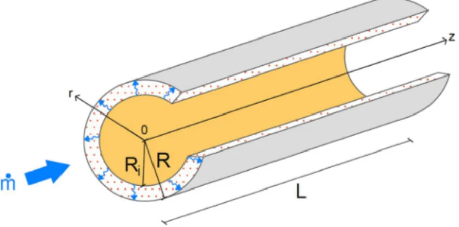
Here we consider a cylinder of radius R and length L. A volume of salt Vs is deposited uniformly along the cyl-inder wall. We hypothesise that one layer of salt grain covers the wall and will consider only diffusion through the grain. Assume that the salt impregnation on the internal tube wall is done at grain scale. The heat transfer fluid (humid air) licks the salt, water vapor diffuses within, allowing the chemical reaction to happen, and heat to be stored or released. The salt thickness is termed e. The volume Vf of humid air blown along the cylinder is
Vf = πRi2L. We have Ri + e = R (Fig. 1).
The inlet boundary conditions (˙m,Tin,cin) remains constant. The salt thickness is chosen so that it corresponds
to the order of magnitude given in Eq. (5), meaning that the time for diffusion through the salt matches the time
for the chemical reaction to happen. Figure 2 shows the value of the advancement for t = t(a=0) + Δt in two cases.
The advancement represents the ratio between the mass of hydrated salt at time t and the mass of fully hydrated
salt. At first, the fluid volume was fixed, together with the channel length (Fig. 2a). The thickness of impregnated
salt varies such that the radii ratio covers the range 0.727 < Ri/R 1. Decreasing Ri/R means increasing the salt
thickness. Next, the channel length and the salt volume remained constant. The tube diameter through which
humid air flows is then a degree of freedom (Fig. 2b). The range of diameters ratio explored is 0.875 < Ri/R 1.
Note that the increase in the reaction advancement becomes steeper when Ri/R → 1 in all the cases.
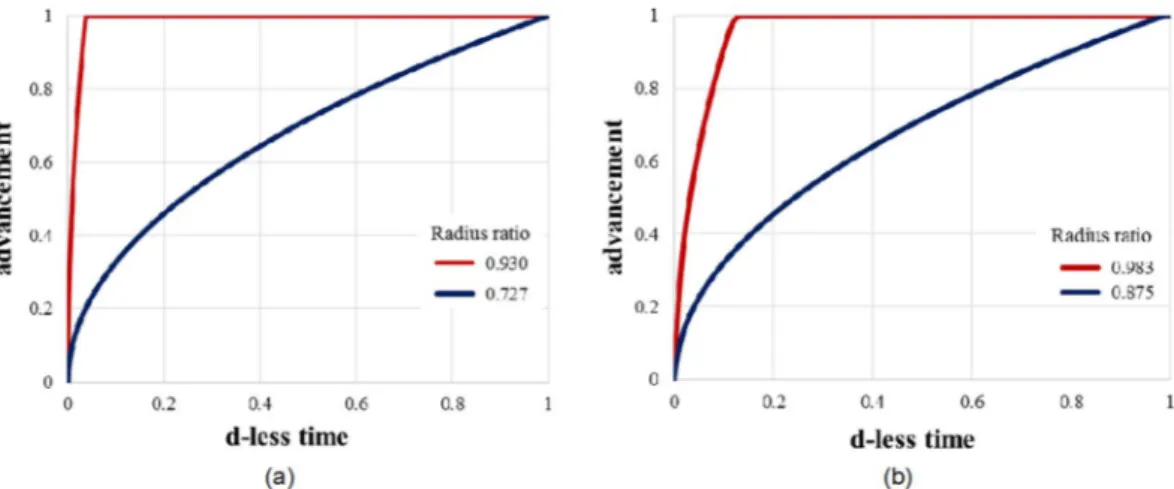
To get more insight on the effect of Ri/R, Fig. 3 shows the reaction advancement as a function of time for some
of the extreme cases. They are Ri/R = 0.727, and Ri/R = 0.930 when the fluid volume is fixed (Fig. 3a), and
Ri/R = 0.875, and Ri/R = 0.983 when the salt volume is fixed (Fig. 3b). In both cases, the reaction advancement
increases with the radii ratio: the thinner the total salt thickness, the higher the advancement of the chemical
reaction. The thermal power produced by the salt reaction is shown in a non-dimensional way in Fig. 4a,b (top)
as a function of the reaction advancement. The d-less power is calculated by dividing the thermal power by the maximum value obtained in each configuration (fixed fluid volume or fixed salt volume), which corresponds to
the case with the smallest radius ratio. The corresponding energy is also determined (Δhn V a t()s s ). It varies
line-Figure 1. Elemental configuration: the heat transfer fluid is channeled through the tube letting water vapor
diffuse radially through the salt impregnated along the tube wall.
Figure 2. The reaction advancement at t = t(a=0) + Δt, when (a) the fluid volume is fixed, and (b) the salt
arly with the reaction advancement, and the salt volume. More information on the kinetics of heat released
appears when plotting the results as a function of the d-less time (see Fig. 4a,b, bottom).
More challenging is the case where the salt volume is fixed together with the fluid volume. Note that the
fluid volume is linked to the salt volume through Vs = π(Ri + e)2L−Vf. The channel inner radius and the salt
thickness are estimated from the theoretical analysis based on the constructal law (see Methods). As the volumes are prescribed, the channel length is not a degree of freedom anymore. Several configurations are picked: one
corresponding to the recommendations obtained from the constructal law in terms of salt thickness (Eq. (5)) and
radius ratio, see Eq. (7). The other configurations continue to obey the radius ratio order of magnitude, yet, the
Figure 3. The reaction advancement as a function of the dimensionless time for 2 extreme cases when (a) the
fluid volume is fixed, and (b) the salt volume is fixed.
Figure 4. The dimensionless thermal power as a function of the advancement (top), and the dimensionless heat
released as a function of the dimensionless time (bottom) for 2 extreme cases when (a) the fluid volume is fixed, and (b) the salt volume is fixed.
www.nature.com/scientificreports
www.nature.com/scientificreports/
salt thickness is either smaller or bigger that the one dictated by Eq. (5). Consequently, the channel length will be
respectively longer or smaller.
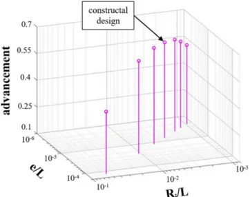
We see in Fig. 5 the evolution of the advancement for a d-less time (t/t(a=1) = 0.141), and various ratios Ri/L
and e/L, while the salt and fluid volumes are always maintained constant. The time was chosen only for the sake of illustration. The trend is identical for other values of time. This figure shows the impact of the geometry on the reaction advancement, and therefore the system performance. Plotted also is the configuration corresponding
to the constructal arrangement. The following figure (Fig. 6a,b) focuses on the two extreme cases (Ri/L ≅ 5 · 10−2
with e/L ≅ 1.3 · 10−4, and R
i/L ≅ 10−3 with e/L ≅ 2.3 · 10−6) surrounding the theoretical results obtained from the
constructal approach, and presents the results in terms of advancement and thermal power. The constructal design is always superior.
Discussion
Thermochemical Energy Storage finds utility in different building applications. The way to design the reactor must be adapted to the objective and the time-scale of the storage. When the fluid volume is fixed, or when the salt volume is fixed, a higher channel radius ratio leads to a faster chemical reaction. The constructal law predicts
that Ri/R should be close to 1, see Eq. (7), provided the salt thickness is in the order of magnitude given by Eq. (5).
For a fixed fluid volume a thinner layer of impregnated salt allows a much faster reaction (Fig. 3a) as the time
for diffusion through the salt is proportional to the square of the salt thickness. Yet the peak value of the released thermal power is quasi identical, regardless the radius ratio, thus the salt volume.
Figure 5. The reaction advancement as a function of the shape ratios e/L and Ri/L with fixed salt and fluid
volumes at t/t(a=1) = 0.141.
Figure 6. The comparison between constructal design and 2 extreme cases (short and large, long and slender):
(a) reaction advancement as a function of the dimensionless time, and (b) thermal power as a function of the advancement.
the radius/length aspect ratio. The design that meets the recommendations dictated by the constructal law allows
a faster reaction advancement (Fig. 5). Decreasing the salt thickness comes with increasing the channel length. As
the fluid residence time increases accordingly, the reaction of the entire salt volume is slower. Shortening the tube length means to increase the salt thickness; this creates an imbalance between the time for molecular diffusion
through the salt and the time for the chemical reaction to happen (Fig. 6a). Morphing the system in accord with
the trends predicted by the theoretical approach leads to more thermal power released even though the salt volume
available for the thermochemical reaction is constant. Note in Fig. 6b that its peak value is significantly higher.
Methods
Constructal configuration.
Mass transfer throughout the salt is mainly radial as the salt thickness (grainscale) is much smaller than the fluid radius. Therefore mass conservation gives23,24
γ ∂ ∂ ≅ ∂ ∂ + ∂ ∂ c t D c r c t (1) v s, s 2 2
where c is the water vapor concentration, Dv,s is the vapor diffusion coefficient through the salt, and γ is a stoichi-ometric coefficient.
Considering Fick’s diffusion alone through the salt of thickness e, the scale analysis of Eq. (1) gives
~ t e D (2) diff v s 2 ,
where tdiff is the time scale of diffusion. The reaction time of the salt (treaction) represents the time necessary for the the chemical reaction to happen. It is given, in an order of magnitude sense, by the time when the water vapor concentration decreases due to the chemical reaction.
γ
Δ ~
c
treaction n ks scin (3)
where ns is the salt molar density and kcin is the kinetic constant.
The constructal law states that the optional allocation of the material volume obeys an equipartition of time
principle25,26, which means here that the time for vapor diffusion through the salt grains tdiff must match the
reac-tion time of the salt volume treacreac-tion. Hence, if in an order of magnitude sense, Δ ~c ns
γ ~ e D kv scin, (4) 1/2 If not, γ Δ ~ e D k c n (5) v s cin s , 1/2
Equations (4) and (5) show that the salt thickness should be chosen as a function of the expected vapor
con-centration drop between inlet and outlet (in an hydration configuration), e~ Δsc, which is a measure of the
number of vapor moles reacting with the salt.
The heat gained by the fluid is given by m c Tf pΔ The heat released during the hydration of the salt is Δh n Vs s
where Δh is the reaction enthalpy. Energy conservation imposes
ρf f pV c TΔ ~Δh n Vs s (6)
www.nature.com/scientificreports
www.nature.com/scientificreports/
ρ − Δ Δ ~ R R c T h n 1 (7) i f p s 2 or ρ + ~ + Δ Δ e R c h n T 1 1 (8) i f p s 2Equation (8) unravels the relationship that exists between e/Ri, the ratio of salt thickness and channel radius,
and the change in fluid temperature.
More information on the channel geometry can be obtained by considering that the heat transfer rate along the channel is mc T pΔ , with m ~ρf ftV
f and tf the fluid residence time in the duct. Maximum heat transfer density
happens when the fluid residence time matches the time for thermal diffusion in the channel
α ~ t R (9) f i f 2
The salt hydration heat rate is Δ ∂
∂ h Vct ss , where ∂ = ∂ ∂ ∂ n c ts s at and ∂∂ a
t is the advancement kinetic of the chemical
reaction. We have27 ∂ ∂ = − − a t k p p a 1 (1 ) (10) cin eq v
where pv is the vapor pressure, and peq is the equilibrium gas pressure. The latter is a function of the temperature
through the Clausius-Clapeyron equation28.
From scale analysis, we write ∂
∂ ~k a
t cin. As Vf ~ LRi2, the first law of thermodynamics writes
Δ ~ Δ k L T kf cin h n Vs s (11) and − Δ Δ ~ R R k T k h n (12) i f cin s 2 2
Combining Eqs (7) and (12) together, we obtain
α ~ R k (13) i f cin 2 and α ρ + Δ Δ ~ R k c T n h 1 (14) f cin f p s 2
Finally, making use of Eqs (5) and (13)
γ α Δ ~ e R D c n (15) i v s s f 2 ,
Model.
In order to test the theoretical results obtained from constructal design, a numerical model wasdevel-oped on a finite elements platform29. The heat transfer fluid was humid air, and the salt was SrBr
2. The main
physical characteristics are provided in Table 1.
The model equations are given by the following conservation laws: (i) Mass conservation of humid air in the channel:
ρ
=
D
Dtf 0 (16)
where ρf is the humid air density. The changes in water vapor content do not impact the humid air proper-ties30.
(ii) Mass conservation of water vapor in the channel (necessary to link with the water vapor diffusion through the salt):
+ ∇ − ∇ =
Dc
Dt ( Dv f, c) 0 (17)
where c is the water vapor concentration, and Dv,f is the vapor diffusion coefficient in the fluid (air). (iii) Mass conservation of water vapor in the salt:
γ
∂
∂ + ∇ − ∇ = −
c
t ( Dv s, c) n dasdt (18)
(iv) Momentum conservation of humid air in the channel, in laminar regime:
ρ ν = − ∇ + ∇ u u D Dt p 1 (19) f 2
where u is the velocity vector. (v) Energy conservation along the tube:
ρc DT + ∇ ⋅
(
∇)
=Dt k T 0 (20)
f pf f
(xvi) Energy conservation through the salt:
∆ ∂ ∂ + ∇ ⋅ ∇ = c T t (k T) n dadt h (21) ps s s
(xvii) Reaction kinetic:
= − − da dt k p p a 1 (1 ) (22) cin eq v
The temperature Tin and the water vapor concentration cin were fixed at the entrance of the fluid cylinder. To
assume a fully developed flow at the inlet, an entrance length greater than 0.05 Re(2Ri) was imposed31, for an inlet
mass flow rate ˙m. The outlet was at atmospheric pressure, and an outflow condition was applied as a boundary
condition for heat transfer. The walls of the cylinder (r = Ri + e) were thermally insulated without any vapor flux. A no-slip condition was imposed at the interface between the fluid and the salt (r = Ri).
At t = 0, the initial temperature of the system was Tinit, the fluid was at rest and at atmospheric pressure. The initial vapor concentration was cinit corresponding to the equilibrium vapor pressure at temperature Tinit.
Due to the axial symmetry, the three-dimensional geometry was simplified to a 2D axi-symmetry one. The model meshing was optimized in a dedicated study where the energy and mass conversation were used as verifi-cation criteria. The model was validated by comparing its results to an experimental study of an open system in
which parallelepiped layers of SrBr2 were submitted to 7 cycles of hydration and dehydration. The input data were
well controlled: moist air temperature, vapor pressure and volumetric air flow rate. More details can be found in
Malley-Ernewein and Lorente32.
Received: 5 September 2019; Accepted: 30 September 2019; Published: xx xx xxxx
References
1. Energy consumption in households - Statistics Explained. Available at: https://ec.europa.eu/eurostat/statistics-explained/index. php?title=Energy_consumption_in_households. (Accessed: 5th August 2019).
2. N’Tsoukpoe, K. E., Schmidt, T., Rammelberg, H. U., Watts, B. A. & Ruck, W. K. L. A systematic multi-step screening of numerous salt hydrates for low temperature thermochemical energy storage. Appl. Energy 124, 1–16 (2014).
www.nature.com/scientificreports
www.nature.com/scientificreports/
3. Li, L., Sun, J. & Li, Y. Thermal load and bending analysis of heat collection element of direct-steam-generation parabolic-trough solar power plant. Appl. Therm. Eng. 127, 1530–1542 (2017).
4. N’Tsoukpoe, K. E., Liu, H., Le Pierrès, N. & Luo, L. A review on long-term sorption solar energy storage. Renew. Sustain. Energy Rev. 13, 2385–2396 (2009).
5. Ferchaud, C., Zondag, H. & de Boer, R. Material research on salt hydrates for seasonal heat storage application in a residential environment. ECN-M–13-022 (2013).
6. Kuznik, F. & Johannes, K. A Review on Chemisorption Heat Storage in Low-energy Buildings. Energy Procedia 57, 2333–2341 (2014).
7. Finck, C. et al. Experimental Results of a 3 kWh Thermochemical Heat Storage Module for Space Heating Application. Energy
Procedia 48, 320–326 (2014).
8. Mette, B., Kerskes, H. & Drück, H. Experimental and Numerical Investigations of Different Reactor Concepts for Thermochemical Energy Storage. Energy Procedia 57, 2380–2389 (2014).
9. Fopah Lele, A., Kuznik, F., Opel, O. & Ruck, W. K. L. Performance analysis of a thermochemical based heat storage as an addition to cogeneration systems. Energy Convers. Manag. 106, 1327–1344 (2015).
10. Solé, A., Martorell, I. & Cabeza, L. F. State of the art on gas–solid thermochemical energy storage systems and reactors for building applications. Renew. Sustain. Energy Rev. 47, 386–398 (2015).
11. Zettl, B., Englmair, G. & Somitsch, W. An Open Sorption Heat Storage Concept and Materials for Building Heat Supply. Energy
Procedia 73, 297–304 (2015).
12. Kuznik, F., Johannes, K. & Obrecht, C. Chemisorption heat storage in buildings: State-of-the-art and outlook. Energy Build. 106, 183–191 (2015).
13. Aydin, D., Casey, S. P. & Riffat, S. The latest advancements on thermochemical heat storage systems. Renew. Sustain. Energy Rev. 41, 356–367 (2015).
14. Fopah-Lele, A. & Tamba, J. G. A review on the use of SrBr2·6H2O as a potential material for low temperature energy storage systems
and building applications. Sol. Energy Mater. Sol. Cells 164, 175–187 (2017).
15. Krese, G., Koželj, R., Butala, V. & Stritih, U. Thermochemical seasonal solar energy storage for heating and cooling of buildings.
Energy Build. 164, 239–253 (2018).
16. Kuznik, F., Johannes, K., Obrecht, C. & David, D. A review on recent developments in physisorption thermal energy storage for building applications. Renew. Sustain. Energy Rev. 94, 576–586 (2018).
17. Bejan, A. Street network theory of organization in nature. J. Adv. Transp. 30, 85–107 (1996).
18. Wechsatol, W., Lorente, S. & Bejan, A. Optimal tree-shaped networks for fluid flow in a disc-shaped body. Int. J. Heat Mass Transf. 45, 4911–4924 (2002).
19. Bejan, A. Why the bigger live longer and travel farther: animals, vehicles, rivers and the winds. Sci. Rep. 2, 594 (2012). 20. Bejan, A. The Physics of Life: The Evolution of Everything. (St. Martin’s Press, 2016).
21. Lucia, U., Grisolia, G. & Astori, M. R. Constructal law analysis of Cl − transport in eyes aqueous humor. Sci. Rep. 7, 1–4 (2017). 22. Lucia, U. & Grisolia, G. Time: a Constructal viewpoint & its consequences. Sci. Rep. 9, 1–7 (2019).
23. Ishida, M. & Wen, C. Y. Comparison of zone-reaction model and unreacted-core shrinking model in solid—gas reactions—I isothermal analysis. Chem. Eng. Sci. 26, 1031–1041 (1971).
24. Ishida, M., Wen, C. Y. & Shirai, T. Comparison of zone-reaction model and unreacted-core shrinking model in solid—gas reactions—II non-isothermal analysis. Chem. Eng. Sci. 26, 1043–1048 (1971).
25. Bejan, A. & Lorente, S. Design with Contructal Theory. (John Wiley & Sons, 2008).
26. Lorente, S. Constructal view of electrokinetic transfer through porous media. J. Phys. Appl. Phys. 40, 2941–2947 (2007).
27. Michel, B., Neveu, P. & Mazet, N. Comparison of closed and open thermochemical processes, for long-term thermal energy storage applications. Energy 72, 702–716 (2014).
28. Moran, M. J., Shapiro, H. N., Boettner, D. D. & Bailey, M. B. Fundamentals of Engineering Thermodynamics. (2014). 29. www.comsol.com.
30. Michel, B., Mazet, N. & Neveu, P. Experimental investigation of an open thermochemical process operating with a hydrate salt for thermal storage of solar energy: Local reactive bed evolution. Appl. Energy 180, 234–244 (2016).
31. Langhaar, H. L. Steady flow in the transition length of a straight tube. J. Appl. Mech. 9 (1942).
32. Malley-Ernewein, A. & Lorente, S. Constructal design of thermochemical energy storage. Int. J. Heat Mass Transf. 130, 1299–1306 (2019).
33. Cussler, E. L. Diffusion, mass transfer in fluid systems. (Cambridge University Press, 1984).
34. Esaki, T. & Kobayashi, N. Reaction Rate Characteristics of SrBr2 Hydration System for Chemical Heat Pump Cooling Mode. J.
Mater. Sci. Chem. Eng. 04, 106 (2016).
Acknowledgements
Alexandre Malley-Ernewein is funded by the French ANR research project DECARTH, ANR-16-CE22-0006-03.
Author contributions
A.M.E. ran the simulations and prepared the figures. S.L. did the theoretical analysis.
competing interests
The authors declare no competing interests.
Additional information
Correspondence and requests for materials should be addressed to S.L.
Reprints and permissions information is available at www.nature.com/reprints.
Publisher’s note Springer Nature remains neutral with regard to jurisdictional claims in published maps and