Publisher’s version / Version de l'éditeur:
Canadian Journal of Civil Engineering, 15, 1, pp. 66-71, 1988-02
READ THESE TERMS AND CONDITIONS CAREFULLY BEFORE USING THIS WEBSITE. https://nrc-publications.canada.ca/eng/copyright
Vous avez des questions? Nous pouvons vous aider. Pour communiquer directement avec un auteur, consultez la première page de la revue dans laquelle son article a été publié afin de trouver ses coordonnées. Si vous n’arrivez pas à les repérer, communiquez avec nous à [email protected].
Questions? Contact the NRC Publications Archive team at
[email protected]. If you wish to email the authors directly, please see the first page of the publication for their contact information.
NRC Publications Archive
Archives des publications du CNRC
This publication could be one of several versions: author’s original, accepted manuscript or the publisher’s version. / La version de cette publication peut être l’une des suivantes : la version prépublication de l’auteur, la version acceptée du manuscrit ou la version de l’éditeur.
Access and use of this website and the material on it are subject to the Terms and Conditions set forth at
Dynamic loading and response of footbridges (1987)
Rainer, J. H.; Pernica, G.; Allen, D. E.
https://publications-cnrc.canada.ca/fra/droits
L’accès à ce site Web et l’utilisation de son contenu sont assujettis aux conditions présentées dans le site LISEZ CES CONDITIONS ATTENTIVEMENT AVANT D’UTILISER CE SITE WEB.
NRC Publications Record / Notice d'Archives des publications de CNRC:
https://nrc-publications.canada.ca/eng/view/object/?id=8bd3aaf6-77f4-4e46-b7a3-736ade084502 https://publications-cnrc.canada.ca/fra/voir/objet/?id=8bd3aaf6-77f4-4e46-b7a3-736ade084502
-
Ser
TH1
N21d
National Research
Conseil national
no.
1 5
57
I+
1
council can&
de recherches Canada
c. 2
BLDG
Institute for
lnstitut de
-
Research
in
recherche en
Construction
construction
Dynamic Loading and Response
of
Footbridges (1
987)
by
J.H. Rainer, G. Pernica and D.E. Allen
AMALYZED
Reprinted from
Canadian Journal of Civil Engineering
Volume 15, No. 1, February 1988
p.
66- 71
(IRC Paper No. 1557)
[
- ~ 9-
r~ 1 3 7f
l a c
i T!
t f 8 R A . 9 ~
! 6 I 1 r r r-
i
$ --
3
135:
i
NRCC 29320
1
f
B I B L I O T H ' E Q G E
! I ?1 R C
I
1
CNRC-
ICIST * L -.- 4Canafl2
8 3
I6098
*
T h i s paper
i s
being d i s t r i b u t e d i n r e p r i n t
form by
the I n s t i t u t e f o r Research i n
Construction.
Al i s t
of b u i l d i n g p r a c t i c e
and r e s e a r c h p u b l i c a t i o n s a v a i l a b l e from
t h e I n s t i t u t e
maybe obtained by w r i t i n g t o
t h e P u b l i c a t i o n s S e c t i o n ,
I n s t i t u t e f o r
Research
i n
C o n s t r u c t i o n , N a t i o n a l Research
C o u n c i l of
Canada,
O t t a w a ,
O n t a r i o ,
KIA OR6.
Ce document
e s t
d i s t r i b u g sous forme de
t i r € - a - p a r t
p a r l t
I n s t i t u t de recherche e n
c o n s t r u c t i o n .
On peut o b t e n i r une l i s t e
d e s p u b l i c a t i o n s de l t I n s t i t u t p o r t a n t
sur
les
techniques ou l e s recherches en m a t i a r e
d e b l t i m e n t e n B c r i v a n t
a
La
S e c t i o n d e s
p u b l i c a t i o n s ,
I n s t i t u t de
recherche
en
c o n s t r u c t i o n ,
C o n s e i l
n a t i o n a l
---.
d e
r e c h e r c h e s
Dynamic loading and response of footbridges
J . H. RAINER, G. PERNICA, A N D D. E. ALLENStructures Section. Institute far Rehearch in Con.struction. National Research Council of Canada, Otrawo. Ont., Canada KIA OR6
Received February 17, 1987 Revised manuscript accepted July 30, 1987
Dynamic forces were measured during walking, running, and jumping, using an instrumented platform. The results are expressed as sinusoidal force amplitudes normalized by the subject's weight and are plotted versus frequency. The maximum dynamic loads for walking were found to be nearly twice as large as those recommended in the 1983 Ontario Highway Bridge Design Code or the British Standard BS.5400, and those for running or jumping, more than six times as large.
Responses of footbridges are calculated using a simple formula based on the dynamic loading due to one person, the response of a simple span at resonance, and limited duration of excitation. Good agreement was obtained with the measured response of two 17 m experimental spans subjected to human excitation, for both the first and second harmonics of the step rate. The resonant vibrations of the spans can be substantially reduced by resonant dampers.
Key n,orrls: footbridges. dynamic loads, dynamic response, design criteria, resonant dampers.
Les forces dynamiqucs ont Ctk mesurkes durant des activitks de marche, de course et de saut, a I'aide d'une plate-forme instrumentee. Les rksultats sont exprimes sous forme d'amplitudes de la force sinuso~dale normaliskes par le poids du sujet; on a ensuite trace la courbe en fonction de la frkquence. En ce qui a trait a la marche, les charges dynamiques maximales se sont revelkes deux fois plus ClevCes que celles recommand6es par I'Ontario Highway Bridge Design Code de 1983 ou la nonne britannique BS5400. Les charges dynamiques des deux autres activitCs Ctaient six fois plus ClevCes.
Le comportement des passerelles a CtC calcule i I'aide d'une formule simple basCe sur le chargement dynamique dB a une personne. la rkponse d'une portke simple en condition de resonance et la duke limitCe de I'excitation. Une bonne similitude a CtC obtenue avec la mesure du comportement de deux portees experimentales de 17 m de long, pour la premiere et la deuxieme harmoniques du taux de pas. Les vibrations resonnantes des portees peuvent &tre considCrablement rkduites par des amortisseurs de resonance.
Mots ciPs : passerelles. charges dynamiques, reponse dynamique, criteres de conception, amortisseurs de resonance. [Traduit par la revue]
Can. J . Civ. Eng 15. 66-71 (1988)
Introduction Forces induced by pedestrian motion
Since the primary purpose of footbridges is the conveyance of A number of previous studies of forces induced by human pedestrians, such bridges need to be safe and to exhibit activity can be found in the following references: Harper et a / .
acceptahle behaviour for users. Walking, running, and jumping (1961), Nilsson (1976, 1980), Ohlsson (1982), and Tuan and produce dynamic forces and, as a consequence, a vibrational Saul (1985). These employed the forces produced by one step response, which can annoy or alarm people. Serviceability will and then formed a simulated walking sequence by adding therefore be a major design consideration. single-step results with appropriate time delays. The present A number of studies have dealt with the problem of vibrating investigation measures directly the continuous dynamic forces footbridges (Tilly et a / . 1984; Blanchard et a / . 1977; Wheeler produced by one or more persons walking, running, orjumping.
1982; Matsumoto et al. 1978). Design requirements and
Testprocedure and oMly sis
guidelines have been established, such as the British Standard
The effects of walking and running were determined for a
BS5400 (BS5400 1978)' the 1983 Ontario Highway Bridge platform 17 m long by installing load cells at a centre support. A
Design Code (OHBDC 1983), and those used in Australia
plan view and elevation of the platform are shown in Fig.
,
.
(Wheeler 1982). The OHBDC bases its design requirements and Further details of the construction and measurement techniques recommendations largely on BS5400; both codes specify a
are presented in Rainer and Pemica (1986). dynamic design load of 180 sin (2lrft) N. The resulting vibrations
The tests were conducted by playing prerecorded pulses at the shall not exceed 0 . 5 6 m m / in BS5400, and less than that in desired walking or running rate through loudspealers, and
0'''
' 1983. Wheeler (1982) presented a study of footbridge requesting the subject to walk or nm along
he span at the pulse vibrations in Australia in which the pedestrian model was a rate using a stride of his own choosing. The lowest natural . sequence of measured single-step force pulses. The acceptance frequency of the instrumented floor
strip was 12 Hz, Useful
level was based On the Kobori
results were limited to frequencies below about 10 Hz, since ,
and Kajikawa (1 974). beyond that frequency the dynamic amplification becomes large
1
This paper presents the results of force measurements from and rather sensitive to damping.
persons walking, running, and jumping, and a comparison I
between calculated and measured responses of two test struc- Results of force measurements
tures. Comparisons are made with available design procedures Walking
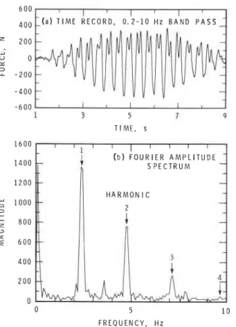
for acceptability of vibrations on footbridges. A typical record of the force induced at the centre support due to a single person walking is shown in Fig. 2a. The record
NOTE: Written discussion of this paper is welcomed and will be contains only the dynamic portion of the induced forces, since received by the Editor until May 3 1 , 1988 (address inside front cover). the static component has been eliminated by a 0.2 Hz high pass
RAINER
PlAN
I PRECAST CONCRETE E L E V A T I O N \ FORCE TRANSDUCER ON TFMPORARY SUPPORT D I M E N S I O N S I N m mFIG. 1. Instrumented platform (span 1).
- 6 0 0
1 5 7 9
TIME, s
E R E C O R D . 0 . 2 - 1 0 H Z B A N D P A S S
F R E Q U E N C Y . H z
FIG. 2. Forces measured at centre support due to subject A walking at 2.4 steps/s.
filter. These forces are bounded by a parabolically shaped envelope that corresponds to the static influence line for the mid-span support of the test platform. At frequencies well
I below the lowest resonant frequency of the platform (12 Hz),
these measured forces at the centre support represent the forces applied to the platform by the moving person, modified by the
'
influence line for the centre support force. For frequency components closer to the resonance frequency of the platform, dynamic amplifications occur in the measured forces. The loading parameters presented here have been corrected for this dynamic effect and for the influence line envelope, and thus represent the force components generated by the moving person
ET AL.
F R E Q U E N C Y . H z
FIG. 3 . Fourier amplitude spectrum of forces due to jumping at 2.2
jumps/s.
on the supporting structure. The Fourier amplitude spectrum of this force record is shown in Fig. 2b. The spectrum shows that the force produced by one person walking consists of distinct frequency components at integer multiples (harmonics) of the footstep rate, with amplitudes that decrease with increasing frequency. The first three or four harmonics comprise the main dynamic components of walking forces. As the time record in Fig. 2a shows, the forces are periodic functions of the footstep rate.
Running
The forces from one person running are similar to those for walking, except that they are truncated below zero during the time the runner is airborne. The Fourier spectrum of the force record again contains discrete frequency components at har- monics of the footstep rate.
Jumping
The jumping forces consist of a sequence of isolated pulses separated by a section of zero force (Allen et al. 1985). The Fourier spectrum of the force record (Fig. 3) again consists of harmonic components similar to that for walking.
Mathematical representation of forces
The above analysis of force records indicates that the forces
( F ( t ) ) from walking, running, and jumping can be represented by
N
[l] F(t) = P 1
(
+ 1
a, sin (n21~ft+
4,)n = l
1
where P = static weight of person; a = Fourier amplitude or coefficient; n = order of harmonic of the footstep rate, n = 1,2, 3
. . .
; f = footstep rate in steps per second; t = time;4
= relative phase angle; N = total number of harmonics.The dynamic component of the activity force in [ l ] is represented by the summation term, which is a Fourier series with Fourier coefficients a, at the discrete frequencies nf. These correspond to the centre amplitudes of the various harmonics of the force record, as in Fig. 2a, normalized by the person's weight (P).
Variation of dynamic forces with step frequency
The key parameters in [I] that describe the dynamic force are the Fourier coefficients (a,) and the footstep frequency (f). In a manner similar to that used to describe rhythmic forces (Allen et al. 1985; Supplement to the National Building Code of Canada 1985), the Fourier coefficients (a,) are called "dynamic load factors," which are defined as the ratio of the force amplitude of each harmonic to the weight of the person. The variation of a,
68 CAN. J. CIV. ENG. VOL. 15, 1988 I l 1 1 1 1 1 1 I
/"4,
H A R M O N I C n 1 ai "
2-
I
3 4 0 v-
f
n pdmn-
0' FREQUENCY. HzFIG. 4. Averaged dynamic load factors for walking, subjects A, B, and C. 1 . 6 H A R M O N I C n 1 . 0 0 . 8 0.6 D
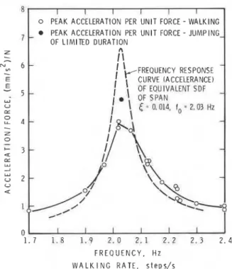
0 PEAK ACCELERATION PER UNlT FORCE - WALKING PEAK ACCELERATION PER UNlT FORCE - JUMPING OF LIMITED DURATION F R E Q U E N C Y . H z Z
-
-
N 6 - V)-
E E W A L K I N G R A T E , s t e p s / sii
I'
FREQUENCY RESPONSE-
I \"CURVE IACCELERANCE)FREQUENCY. Hz FIG. 7. Peak acceleration per unit force and frequency response FIG. 5. Averaged dynamic load factors for running, subjects A, B, curve for 'pan 2.
and C. y 5 - I
'
OF EOUIVALENT SDF-
Y U CL 0 L L 4 --
-
Z 0-
I- 3 --
a ar W 2:
2 - 0 1 2 3 4 5 6 7 8 9 1 0 FREQUENCY. HzFIG. 6. Averaged dynamic load factors for jumping, subjects A, B, and C.
3.0 Hz, running rates between 1.6 and 4.0 Hz, and jumping rates from 1.0 to 4.0 Hz. The results of each activitv for the test subjects were averaged and are shown in Figs. 4-6. Results for individual test subjects are similar to the averaged ones and are presented by Rainer and Pernica (1986) for walking and running. Figure 4 shows that for walking, the dynamic load factor of the first harmonic (a,) is the largest, at 2.4 Hz, and reaches an averaged maximum of 0.52. For running, Fig. 5 shows a maximum averaged value for a, of about 1.4betkeen 2.8 and 4.0 Hz, whereas for jumping, Fig. 6 shows the maximum averaged a l to be about 1.75 between 2 and 3 Hz.
Not all of these rates are equally likely to occur in practice, however. Walking rates are generally within 1.7-2.3 steps/s, with a mean rate of 2.0 (Matsumoto et al. 1978), whereas running or jogging rates are 2-3 steps/s.
For groups of two or four people jumping to a common timing signal, the peak value for a l was little different than that for a single person jumping, although the peaks for the second harmonic are about 15% lower. For eight persons jumping, however, the dynamic load factor for the first harmonic was about 15% lower, and that of the second harmonic (a2), 50%
lower than that for a single male. The third harmonic (ag) was reduced even more relative to that for one person.
Response of test spans to pedestrian movement
Two simply supported test spans were located side by side for dynamic testing. Span 1, the trussed span shown in Fig. 1, but with the centre support removed, had a fundamental natural frequency (f) of 4.17 Hz. Span 2, a structure of equal length and decking but using two wide-flange beams as the main structural members, had a fundamental natural frequency (f) of 2.05 Hz. A single test subject weighing 735 N was used to excite the spans at selected step frequencies as given by an audible pulse. The response of each span was measured by two vertical accelerometers at mid-span; their signals were added, recorded, and analyzed. The dynamic load factors for walking and running for the test subject were reported by Rainer and Pernica (1986) under "subject A."
Span 2, f = 2.05 Hz
The peak acceleration response of span 2 to different walking rates is shown in Fig. 7. This plot has been normalized by the force input, i.e., by the weight of the test subject times the dynamic load factor applicable to each walking rate. The peak response occurs when the walking rate coincides with the fundamental frequency of the span. These results were com- pared with the steady state frequency response curve of the span ,
in the form of "accelerance" (acceleration/force input) at
,
mid-span, shown in Fig. 7 by the dashed line. At resonance, theI
normalized response from walking is considerably lower than , that for steady state, whereas below and above resonance, the peak response for walking is slightly larger. The difference at resonance is caused by the limited duration and changing amplitude of the effective walking force (Fig. 2a). Away from resonance, the larger walking responses can be attributed to beating between the forced response at the walking frequency and the simultaneously excited vibration at the resonance
RAINER ET AL. 69
NUMBER OF CYCLES PER SPAN
FIG. 8. Dynamic amplification factor for resonant response due to sinusoidal load moving across simple span.
frequency of the span. It is the response at resonance that is maximum, however, and only this will be addressed here.
r
Calculation of resonant response Walking
To calculate the peak dynamic response at mid span, the span is modelled as an equivalent single-degree-of-freedom (SDF) oscillator. The amplitude of the sinusoidal excitation at the walking frequency is F = a P . As the pedestrian crosses the span, the effective force variation across the span is enveloped by a curve corresponding to the fundamental mode shape with maximum a P occumng at mid-span. When such a force variation is applied to the SDF vibration model of the span, the maximum response is given by a dynamic amplification factor
(a),
similar to, but smaller than, the dynamic amplificationfactor for steady state excitation. The factor
cP
for simply supported spans as a function of the number of cycles applied and various damping ratios has been calculated and is presented in Fig. 8. This amplification factor decreases with an increase in the damping ratio and increases monotonically towards the steady state solution with increasing number of cycles of excitation, i.e., with the number of steps it takes the person to traverse the span. Thus, the peak acceleration response ( a ) at the fundamental frequency is given bya P / k is the static displacement at mid-span due to the dynamic force amplitude, and multiplicaion by ( 2 ~ f ) ~ converts the displacement to acceleration.
An alternate expression for [2] is obtained by substituting (2,rrf)' = klrn:
where rn = mass of equivalent SDF oscillator. For a uniform simply supported beam, rn = 17/35 times the total mass (M) of the span, which is often approximated as rn = 0.5M. Thus,
Equation [3] indicates that the acceleration response of a span when excited at its natural frequency is directly proportional to the dynamic load
(aP)
and the amplification factor ( a ) , and inversely proportional to the total mass of the span.For calculating the response of span 2 to walking, the following data were used: a = 0.41 (subject A, Rainer and
1 0 TIME, s
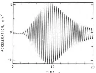
FIG. 9. Response of span 2 to walking at 2.06 steps/s.
10 TIME, s
FIG. 10. Response of span 2 due to jumping at resonance frequency. Pernica 1986); P = 735 N;
cP
= 20 for damping ratio of 1.43% and 19 steps (Fig. 8); k = measured stiffness of span at centre, 897 000 N/m; f = resonance frequency of span, 2.05 Hz.Substitution in [2] gives a peak acceleration of 1.06 m/s2, or 11% of gravity. This compares well with the maximum measured response at resonance of 1.14 m/s2. Figure
9
shows the response of span 2 to the test subject walking at a rate that coincides with the natural frequency of the span.Running
The response of span 2 to running is, as for walking, given by [2] or [3]. With a dynamic load factor a = 1.1 at 2.05 Hz (subject A, Rainer and Pemica 1986), the calculated peak acceleration is 3.14 m/s2. The measured acceleration for the test subject running at 2.05 steps/s is 3.3 m/s2. When the running rate does not coincide with the resonance frequency of the span, the response is significantly reduced; at 3.0 steipsls, a peak acceleration of 0.4 m/s2 was measured.
Jumping
Span 2 was excited at the resonance frequency by the test subject jumping at centre span, and the response is shown in Fig. 10. Since this represents a steady state excitation, much greater response can be expected than from walking or running. At the peak acceleration of 5 m/s2 (and up to 6 m/s2 for other tests) the excitation was stopped, but this was evidently not the limit to which the span could have been excited. Using a = 1.7 at 2.05
Hz
(subject A, Rainer and Pernica 1986), this response70 CAN, 1. CIV. ENG. VOL. 15, 1988
of 6.0 m/s2 corresponds to an acceleration-to-force ratio of (4.8 m m / s 2 ) / ~ and is shown in Fig. 7 by the solid circle. An upper-bound response, corresponding to the peak of the frequency response curve in Fig. 7, can be calculated from the relation applicable to steady state excitation:
or, with the substitution as for [3]:
where = critical damping ratio.
For span 2 this gives a peak acceleration of 8.0 m/s2 or a peak dynamic displacement of 49 mm. The possibility that the damping ratio changes at these large amplitudes needs to be considered. It seems plausible, however, that a response close to this full resonance can be reached. Such a response level, often referred to as "vandal" excitation, should thus be considered in the design procedure and a check on stresses carried out.
Span 1, f = 4.17 Hz
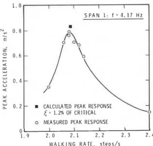
The results from the force measurements presented in Figs. 4-6 indicate substantial components also at twice and, to a lesser degree, at 3 or 4 times the walking, running, or jumping rate (Rainer and Pernica 1986). Thus a resonant condition could also be produced at these higher harmonics. This was investi- gated on span 1. Walking rates were chosen so that the second harmonic of the forces falls near the natural frequency of the span. The measured peak accelerations are shown in Fig. 11. A peak acceleration of nearly 0.8 m/s2 occurred at a walking rate of 2.08 steps/s, which corresponds to an excitation frequency of 4.16 Hz provided by the second harmonic of the walking forces. The response to walking of span 1, having a natural frequency of 4.17 Hz, will now be determined by the proposed procedure, [2], or [3]. For the test subject walking, the dynamic load factor
a2 of the second harmonic at 4.17 Hz is 0.20; for 36 cycles,
double the number of steps, the amplification factor = 31,
from Fig. 8 for the applicable damping ratio
P
= 1.2%.Substitution in [2] gives
This compares with a measured peak response by the test subject of 0.80 m/s2 for walking.
Comparisons with BS5400 and OHBDC
The procedure used here and the methods outlined in BS5400 (1978) and OHBDC (1983) need to be compared using a consistent set of assumptions. Although the stated forcing
function in BS5400 and OHBDC is F = 180(sin 27rfi) N to
represent forces from walking, this is not used explicitly. Instead, the acceleration is calculated from an equivalent static
deflection (w,) due to a person weighing 700 N:
[6] a = 4r2f 2 ~ , ~ +
where f = natural frequency of span; K = configuration factor;
+
= dynamic response factor.The stiffness k at the centre of span 2 was measured as 897
N/mm, so the deflection due to a 700 N person is w, = 0.780
mrn, K = 1.0 for a simple span, and
+
= 7.5 fram the graphs inI I I I
S P A N 1: f = 3 . 1 7 H z
-
-
CALCULATED PEAK RESPONSE= 1.2% OF CRITICAL o
o MEASURED PEAK RESPONSE
I I I I
0
1 . 9 2 . 0 2 . 1 2 . 2 2. 3 2 . 4 W A L K I N G R A T E , s t e p s / s
1
FIG. 1 1 . Peak responses of span 1 to walking.
OHBDC (1983) and BS5400 (1978). Thus the calculated '
acceleration (a) is 0.97 m/s2.
The response calculation given by [2] or [3] results in a peak
acceleration (a) of 1.06 m/s2, using f = 2.03 Hz, a = 0.41,
P = 735 N, and @ = 19 for 18 steps at 1.4% damping. This
com ares favourably with the measured peak response of 1.05
h'
m/s for the fundamental mode.
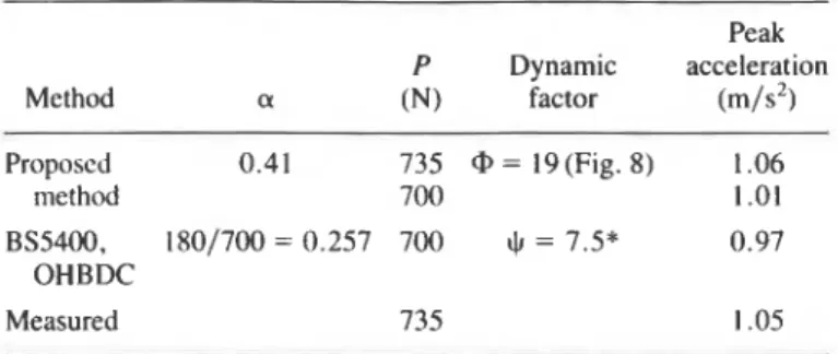
Although the final answers from BS5400 and OHBDC and the method proposed here are in good agreement, the values for the parameters used are quite different (Table 1).
The differences in a and the dynamic factors
0
and+
largelycompensate
one
another in the two calculation methods. Theproposed method, however. has a wider application in that it
would permit a desiper or investigator to substitute different
parameters that are applicable to other specific loading cases.
For example, [2] and 131 apply to walking and running for one or
more people in step, and [4]
and
[5] apply to jumping. Theseformulas can also be used with other than the first harmonic of
the forcing function, as, for example, when the natural frequency of the span coincides with the second harmonic of the excitation.
The criterion given by BS5400 is that the peak response
shouldnotexceed0.5~fm/s2. For span 1,0.5-= 1.02
m/s2, and for span 2,0.5- = 0.72 m/s2. The permissible
values in the OHBDC are 0.75 and 0.44 m/s2 for span 1 and span 2, respectively. Thus the observed accelerations for
walking on spans 1 and 2 just exceed the criteria under BS5400,
whereas the accelerations on both spans substantially exceed the criteria under OHBDC. A subjective assessment by the inves-
tigators would support the OHBDC result, although this i
perception would not necessarily be applicable to in-service behaviour.
Response reduction by resonant dampers I
Resonant dampers were constructed with natural frequencies I
of 2.06 and 2.14 Hz, applied at mid-span of span 2. A series of
'
walking tests was performed and the resulting peak accelera- tions for various damper properties plotted in Fig. 12. Compari- son with results without the damper shows major reductions in peak accelerations, well below the criteria quoted above. A similar observation was made when a resonant damper was
RAlNER ET AL. 7 1
TABLE I. Response calculations and measured values for span 2
Peak P Dynamic acceleration Method a (N) factor (m/s2) Proposed 0.41 735 @ = 19 (Fig. 8) 1.06 method 700 1 .OI BS5400, 180/700 = 0.257 700
+
= 7.5* 0.97 OHBDC Measured 735 1.05*From British Standard BS5400 (BS5400 1978) and the Ontario Highway
Bridge Design Code (OHBDC 1983).
I I 1 1 I 1
RESONANT DAMPER PROPERTIES
MASS. FREQUENCY, DAMPING,
kg Hz % C R I T I C A L D
.
181 2.06 11 a 163 2.14 9-
f I I I 1 1I
1 . 7 1 . 8 1 . 9 2 . 0 2 . 1 2 . 2 2 . 3 2 . 4 W A L K I N G R A T E , s t e p s / sFIG. 12. Response reduction due to resonant damper. applied to span 1. Thus, the objectionable vibrations at the resonant frequencies o f the spans can be drastically reduced by a n appropriately sized resonant damper. This confirms what
other investigators (Tilly et al. 1984; Wheeler 1982; Matsumoto
et al. 1978) have reported. Footbridges could therefore be
designed with a resonant damper, o r provision can be made for using one as a retrofit measure, should objectionable vibrations occur. T h e latter strategy may b e a cost-effective solution, particularly in view of uncertainties in estimating damping and calculating the natural frequency of the structure.
Conclusions
I Dynamic forces for walking, running, and jumping have been
, presented for the range of step frequencies usually associated
with these activities. T h e loading function primarily consists of up to four harmonic components with frequencies of integer multiples o f the footstep rate and decreasing amplitudes for the higher frequencies.
A procedure is described for evaluating the response of
simple spans to walking, running, and jumping excitations at the resonance frequencies. T h e peak acceleration response at the frequency resonance of t w o test spans is computed. This is
similar t o the method in BS5400 and O H B D C , except that the
latter t w o d o not fully reflect the actual loading functions. The new procedure permits the designer to employ other loading functions that may b e applicable t o footbridges, as, for example, where excitation arises from the second harmonic component of pedestrian movement. T h e predicted peak acel- erations are verified by tests o n two laboratory footbridges. It is suggested that the response to jumping also b e considered in design.
Acknowledgements
This paper is a contribution of the Institute for Research in Construction, National Research Council of Canada.
ALLEN, D. E., RAINER, J. H., and PERNICA, G. 1985. Vibration
criteria for assembly occupancies. Canadian Journal of Civil Engineering, 12: 617-623.
BLANCHARD, J., DAVIES, B. L., and SMITH, J. W. 1977. Design
criteria and analysis behaviour of bridges. Department of Transport, Crowthorne, England, TRRL supplementary report SR275, pp. 90-106.
BS5400. 1978. Steel, concrete and composite bridges. Part 2. Specification for loads. British Standards Institution, London, England.
HARPER, F. C., WARLOW, W. J., and CLARK, B. L. 1961. The forces
applied to the floor by the foot in walking. Building Research Station, National Building Studies Research Paper 32, HMSO, London, England.
K o e o ~ r , T . , and KAJIKAWA, Y . 1974. Psychological effects of
highway bridge vibrations on pedestrians. Transactions, Japan Society of Civil Engineering, 6: 41.
MATSUMOTO, Y., NISHIOKA, T . , SHIOJIRI, H., and MATSUZAKE, K.
1978. Dynamic design of footbridges. International Association for Bridge and Structural Engineering, Proceedings, P-17/78, pp. 1-15.
NILSSON, L. 1976. Impact loads produced by human motion. Part 1:
Document D13:1976. Swedish Council for Building Research, Stockholm, Sweden.
1980. Impact loads produced by human motion. Part 2: Document D20:1980. Swedish Council for Building Research, Stockholm, Sweden.
OHBDC. 1983. Ontario Highway Bridge Design Code 1983 and Commentary. Ministry of Transportation and Communications, Toronto, Ont.
OHLSSON, S. 1982. Floor vibrations and human discomfort. Depart-
ment of Structural Engineering, Chalmers University of Technology, GBteborg, Sweden.
RAINER, J. H., and PERNICA, G. 1986. Vertical dynamic forces from
footsteps. Canadian Acoustics, 14: 12-21.
SUPPLEMENT TO THE NATIONAL BUILDING CODE OF CANADA. 1985.
Commentary A, serviceability criteria for deflections and vibra- tions. National Research Council of Canada, Ottawa, Ont., pp. 146-152.
TILLY, G. P., CULLINGTON, D. W., and EYRE, R. 1984. Dynamic
behaviour of footbridges. International Association for Bridge and Structural Engineering, Surveys, S-26/84, pp. 13-24.
TUAN, C. Y., and SAUL, W. E. 1985. Loads due to spectator movements. ASCE Journal of Structural Engineering, 111: 418- 434.
WHEELER, J. E. 1982. Prediction and control of pedestrian induced
vibration in footbridges. ASCE Journal of the Structural Division, lOS(ST9): 2045-2065.