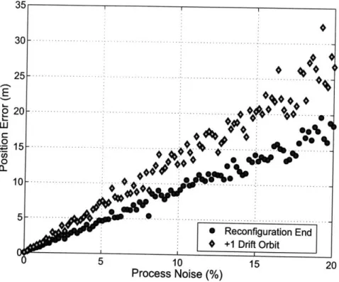
Closed-loop control of spacecraft formations with applications on SPHERES
Texte intégral
Figure
Documents relatifs
Second, I developed a platform to identify and characterize new serine recombinase systems from Mycobacteriophage genomes in order to extend
abscessus complex strains in vitro and ex vivo in a macrophage infection model.. Due to
Huang, “State-of-charge balance using adaptive droop control for distributed energy storage systems in DC microgrid applications,” IEEE Transactions on Industrial Electronics,
injected from the ISOLDE beam line at the full transport voltage of 60 kV while the reference mass is alternately injected (without changing the magnetic field) at its required
In this dissertation, two ways to deal with this abundance of visual features are investigated. The first possibility is to select the visual features that are the most
• The study incorporates the driving behaviour model, the wheelchair model and a feedback controller in a closed-loop system, to adapt the control of the wheelchair to the
Abstract— This paper introduces the adaptive bias and adap- tive gain (ABAG) algorithm for closed-loop electronic speed control (ESC) of the brushless direct current (BLDC)
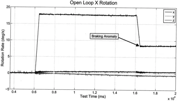
This description of the relative dynamics will be used next to write the robust xed-time spacecraft rendezvous
