HAL Id: tel-01921219
https://hal.univ-lorraine.fr/tel-01921219
Submitted on 2 Oct 2019
HAL is a multi-disciplinary open access
archive for the deposit and dissemination of sci-entific research documents, whether they are pub-lished or not. The documents may come from teaching and research institutions in France or abroad, or from public or private research centers.
L’archive ouverte pluridisciplinaire HAL, est destinée au dépôt et à la diffusion de documents scientifiques de niveau recherche, publiés ou non, émanant des établissements d’enseignement et de recherche français ou étrangers, des laboratoires publics ou privés.
Study of the effect of silica nanoparticles on the
electrochemical analysis of ions at the liquid-liquid
interface
Martha Collins
To cite this version:
Martha Collins. Study of the effect of silica nanoparticles on the electrochemical analysis of ions at the liquid-liquid interface. Theoretical and/or physical chemistry. Université de Lorraine, 2018. English. �NNT : 2018LORR0136�. �tel-01921219�
AVERTISSEMENT
Ce document est le fruit d'un long travail approuvé par le jury de
soutenance et mis à disposition de l'ensemble de la
communauté universitaire élargie.
Il est soumis à la propriété intellectuelle de l'auteur. Ceci
implique une obligation de citation et de référencement lors de
l’utilisation de ce document.
D'autre part, toute contrefaçon, plagiat, reproduction illicite
encourt une poursuite pénale.
Contact : [email protected]
LIENS
Code de la Propriété Intellectuelle. articles L 122. 4
Code de la Propriété Intellectuelle. articles L 335.2- L 335.10
http://www.cfcopies.com/V2/leg/leg_droi.php
Sujet de thèse:
Etude des effets des nanoparticules de silice
sur la détection électrochimique des ions à
l’interface liquide-liquide
Par
Martha Collins
Pour l’obtention du titre de
Docteur de l’Université de Lorraine en Chimie
Directeur:Prof. Marc Hébrant – Professeur à LCPME, Villers-lès-Nancy, France
Co-directeur :
Dr. Grégoire Herzog – Chargé de Recherche à LCPME, Villers-lès-Nancy, France
Rapporteurs:
Dr. Daniela Iacopino – Researcher à Tyndall National Institute, Ireland Dr. Mark Platt – Senior Lecturer à Loughborough University, UK
Examinateurs:
Dr. Agnès Hagège – Chargé de Recherche à Institut des Sciences Analytiques, Lyon, France Prof. Sabine Bouguet-Bonnet – Professeur à Université de Lorraine, France
Ecole Doctorale:
Synthèse, Simulations, Applications: de la Molécule aux Edifices Supramoléculaires (SESAMES) ED 412.
Date de soutenance: 21/09/18
Laboratoire de Chimie Physique et Microbiologie pour les Matériaux et l’Environnement (LCPME)
UMR 7564, CNRS / Université de Lorraine
Page | iii
Title of thesis:
Study of the effect of silica nanoparticles on
the electrochemical analysis of ions at the
liquid-liquid interface
by
Martha
Collins
To obtain the title of
Doctor of Chemistry from the University of Lorraine
Supervisor:Prof. Marc Hébrant – Professor at LCPME, Villers-lès-Nancy, France
Co-supervisor:
Dr. Grégoire Herzog – Researcher at LCPME, Villers-lès-Nancy, France
Reviewers:
Dr. Daniela Iacopino – Researcher at Tyndall National Institute, Ireland Dr. Mark Platt – Senior Lecturer at Loughborough University, UK
Examiners:
Dr. Agnès Hagège – Researcher at Institut des Sciences Analytiques, Lyon, France Prof. Sabine Bouguet-Bonnet – Professor at University of Lorraine, France
PhD school:
Synthèse, Simulations, Applications: de la Molécule aux Edifices Supramoléculaires (SESAMES) ED 412.
Defence date: 21/09/18
Laboratoire de Chimie Physique et Microbiologie pour les Matériaux et l’Environnement (LCPME)
UMR 7564, CNRS / Université de Lorraine
Page | v
ACKNOWLEDGEMENTS:
Firstly I would like to express my deepest gratitude to my supervisors, Marc Hébrant and Grégoire Herzog, for their advice, support and the opportunities they have given me throughout my time in France. Their help and guidance during the course of this research has been invaluable and for that I am greatly appreciative.
I also wish to acknowledge those that have contributed to this work; Aurélien Renard for BET analysis, Céline Caillet for zeta potential measurements, Clare Genois for ICP analysis, Christelle Despas for elemental analysis, Guillaume Sautrey for capillary electrophoresis experiments. Furthermore I would like to thank Claire Genois, our lab technician for always ensuring chemical stocks were up to date. To the work shop team of Jean-Paul Moulin and Gérard Paquot, thank you for your technical support when mechanical problems arose during experiments. Thank you to Marie Tercier, Christelle Charbaut and Jacqueline Druon for their help with administration issues.
The multi-cultural ELAN team, forever evolving with students coming and going over the three years, has always been a lovely group to work with. Arriving here three and a half years ago to do my masters placement, I immediately made friends with Lukasz Poltorak, who was a final year PhD student at the time. He imparted so much information on the topic of liquid-liquid electrochemistry to me and also helped me with the experimental aspect of it, as did Alonso Gamero, a post doc researcher who started about the same time as me. Lin Zhang was a second year PhD student and Maciej Mierzwa, Tauqir Nasir and Cheryl Maria Karman were first year PhD students when I first arrived here. Najwa Jajuli did her masters placement with me and then came back for a year in 2017 for part of her PhD research. To say these people were just my friends would be an understatement. We were all so close and I really enjoyed spending time with them both in the lab and outside of it.
An extra special acknowledgement goes to Cheryl, not only was she my office buddy but also my house-mate for over two years. Going through all the ups and downs of life, both professionally and personally, was made so much easier knowing that we were always there to support each other. I made a friend for life, and I am blessed that she is one that can make amazing cakes and desserts too!
Page | vi To Samuel and Christelle who started their PhD’s the year after me, as well as ALL the first years who started last year – Ning, Wang, Deomila, Himanshu, Joanna, Wahid, Guofeng and Taisia, thank you for your friendship and for filling the lab with activity! Furthermore, Taisia, my new house-mate, I couldn’t have found a nicer person to share the apartment with after Cheryl left, thank you for your friendship and kindness, and your ability to make great cakes too! To the rest of the LCPME and everyone else I met in France along the way, I just want to say thank you for being part of my story here.
And finally, to my family and friends back home who have helped me through these three and a half years, I am forever indebted to ye and ye will never know the extent of my gratitude. Megan and Hannah, I want to say thanks for being there for me, always ready for a chat, even though we rarely got to meet face to face! Donna, you get an honourable mention. I am so grateful for your help and support when I needed it most. To my brother Declan, thank you for being my brother! There aren’t even words to express how thankful I am to my mom and dad, for all their love and support, on the good days and the bad, and for taking care of my three babies - Pet, Libby and Pippa (dog, cat and car!). Ivan, ma dude, you have been there every step of the way, your patience is incredible and I count my lucky stars every day that you are in my life. It’s almost time for this chapter to end and the next one to begin… the excitement!! ☺
And of course, last but not least, I am grateful to the Ecole Doctorale SESAMES (ED 412, Université de Lorraine) for my PhD funding.
Page | vii
TABLE OF CONTENTS:
Résumé: ... 1
Abstract: ... 2
1. Introduction: ... 3
1.1 Interface between Two Immiscible Electrolyte Solutions (ITIES) ... 3
1.1.1 Liquid-liquid interface structure... 4
1.1.2 Charge transfer reactions at the ITIES ... 5
1.1.2.A Simple ion transfer reaction ... 5
1.1.2.B Assisted ion transfer reaction ... 7
1.1.2.C Electron transfer reaction ... 9
1.1.3 Potential window for ion transfer ... 9
1.1.4 Sensitivity and selectivity at the ITIES ... 11
1.1.5 Particle assembly at the ITIES ... 13
1.2 Nanoparticles ... 15
1.2.1 Nomenclature and physicochemical properties of silicon and silicon containing compounds ... 16
1.2.2 Silica nanoparticles ... 18
1.2.2.A Dense Silica Nanoparticles (DSNs) ... 19
1.2.2.B Mesoporous Silica Nanoparticles (MSNs)... 20
1.3 Molecular imprinting ... 26
1.3.1 History of Molecular Imprinting ... 27
1.3.2 Interactions in Molecular Imprinting ... 28
1.3.3 Molecularly Imprinted Polymers ... 29
1.3.4 Molecularly Imprinted Silica ... 30
2. Materials and Methods: ... 33
2.1 Chemicals ... 33
Page | viii
2.3 Instrumentation ... 42
2.4 Protocols ... 46
2.4.1 Preparation of BTPPA+ TPBCl- ... 46
2.4.2 Preparation of counter electrode ... 47
2.5 Dense (DSNs) and Mesoporous (MSNs) silica nanoparticles ... 49
2.5.1 Product specification for DSNs ... 49
2.5.2 Synthesis of MSNs ... 50
2.5.3 Characterisation of DSNs and MSNs ... 51
2.5.3.1 Zeta potential measurements for DSNs and MSNs ... 51
2.5.3.2 Gas adsorption volumetry measurements for MSNs ... 52
2.5.4 Protocol for pre-concentration of Methylene Blue with DSNs ... 54
2.5.5 Protocol for pre-concentration of Methylene Blue with MSNs ... 55
2.6 Non-imprinted (NINs) and Diclofenac-imprinted (DINs) silica nanoparticles ... 55
2.6.1 Synthesis of NINs... 55
2.6.2 Synthesis of DINs... 56
2.6.3 Characterisation of NINs and DINs ... 57
2.6.3.1 Elemental analysis of NINs and DINs ... 57
2.6.3.2 Zeta potential measurements for both silica nanoparticles ... 58
3. Silica nanoparticle adsorption at the liquid-liquid interface (LLI) and interaction with ions ... 59
3.1 Adsorption of dense and mesoporous silica nanoparticles at the LLI ... 60
3.1.1 DSNs adsorption at the LLI ... 60
3.1.2 Effect of ionic strength and pH on DSNs adsorption to LLI ... 62
3.1.3 MSNs adsorption at the LLI ... 64
3.2 Interaction of DSNs with TEA+ at the LLI and effect of solution parameters ... 67
3.2.1 TEA+ transfer across the LLI in the presence and absence of DSNs ... 67
Page | ix
3.2.3 Effect of pH of solution ... 71
3.3 Conclusion ... 75
4. Interaction of dense and mesoporous silica nanoparticles with cations and anions... 76
4.1 Investigation of MB+ adsorption onto silica nanoparticles in aqueous solutions ... 77
4.1.1 Calculation of Kads for MB+ to DSNs and MSNs using UV/Vis spectroscopy .. 77
4.1.2 Study of kinetics of MB+ adsorption and desorption to DSNs and MSNs via Stopped-flow technique... 83
4.2 Electrochemical experiments with MB+ and silica nanoparticles at the LLI ... 88
4.2.1 Thermodynamic studies of MB+ adsorption to DSNs and MSNs at the LLI ... 88
4.2.2 Improving detection sensitivity via pre-concentration with silica nanoparticles95 4.2.3 Ion – pairing and selective extraction using DSNs at the LLI ... 98
4.3 Conclusion ... 104
5. Molecularly imprinted dense silica nanoparticles ... 106
5.1 Spectroscopic evidence for formation of Diclofenac-imprinted cavities ... 108
5.1.1 Infrared spectroscopic analysis of DINs ... 108
5.1.2 UV/Vis spectroscopy of Diclofenac with DINs ... 110
5.2 Spectroscopic investigation of NINs and DINs interactions with Diclofenac and its analogues in aqueous solution ... 111
5.2.1 Calculation of Ka for Diclofenac Na to NINs and DINs using UV/Vis spectroscopy ... 111
5.2.2 Investigation of interactions between DINs and Diclofenac analogues in solution ... 114
5.3 Chromatographic analysis of interactions between Diclofenac and DINs in solution .. ... 117
5.3.1 Comparison of results for Diclofenac Na adsorption to DINs obtained with UV/Vis spectroscopy and HPLC... 120
5.4 Investigation of the selectivity of DINs in solutions of Diclofenac and Diclofenac’s analogues ... 121
Page | x 5.4.1 HPLC experiments with Diclofenac and its analogues, using columns loaded
with NINs and DINs ... 122
5.4.2 Capillary electrophoresis experiments with NINs and DINs as pseudo-stationary phases ... 123
5.5 Electrochemical study of interactions between NINs/DINs and Diclofenac in solution at the LLI ... 125
5.6 Conclusion ... 127
6. General conclusions ... 128
7. Future perspectives ... 130
Bibliography: ... 135
Appendix 1: Electrochemical cell setup ... 156
Appendix 2: Solubility issues with Diclofenac and its analogues ... 157
Appendix 3: Attempts to investigate the selectivity of DINs... 161
Summary: ... 172 159 161 172 157
Page | 1
RESUME:
L’interface entre deux solutions électrolytiques immiscibles (ITIES) peut agir comme un support pour l’assemblage de nanoobjets. Cela présente de nombreux avantages : les particules ne requièrent pas d’ingénierie particulière pour leur obtention, peuvent s’assembler dans des conditions qui leur sont propres, sont pratiquement non dégradables et facilement renouvelables. Les recherches actuelles portent tant sur leur utilisation potentielle en tant que plateformes pour des appareils optiques ajustables, pour des capteurs ou encore pour de la catalyse.
L’adsorption de nanoparticules de silice, dense ou mésoporeuse, à l’interface liquide-liquide a été étudiée par voltammétrie en courant alternatif. L’interaction des nanoparticules de silice avec le bleu de méthylène et l’éosine B a été étudiée par voltammétrie cyclique et spectrophotométrie. Les constantes thermodynamiques d’adsorption du bleu de méthylène ont été déterminées à 1.66 105 et 3.68 103 sur les particules de silice dense et mésoporeuse
respectivement. La variation de constante entre les deux types de silice repose essentiellement sur leur état d’ionisation respectif. L’énergie de Gibbs de transfert entre phase liquide est modifiée de 8.9 kJ mol-1 en présence de nanoparticules denses ce qui donne des indications
sur le mécanisme de transfert du bleu de méthylène en présence de nanoparticules. Mettant à profit l’aptitude de la silice à accumuler le bleu de méthylène et à s’adsorber sur l’interface liquide il nous a été possible d’améliorer la sensibilité de la détection électrochimique. L’éosine B n’a aucune interaction avec les particules de silice.
Nos efforts ont ensuite porté sur l’amélioration de la sélectivité du transfert électrochimie par l’utilisation de nanoparticules de silice à empreinte moléculaire. Des nanoparticules de silice dense à empreinte moléculaire de Diclofénac (DIN) ont été synthétisées. Cette molécule est un anti-inflammatoire non stéroïdien très largement utilisé et figurant sur la liste européenne des polluants émergents. Les constantes d’affinité du Diclofénac pour les DIN et les particules équivalentes sans empreinte sont de 7.47 108 et 2.96
107 respectivement ce qui démontre clairement la présence d’empreintes ayant une forte
affinité pour le diclofénac au sein des particules. Des molécules analogues (Diclofénac acide, Aceclofenac, acide 4 phenyl-azo benzoique) ont été testées et ont une affinité faible pour les DIN. En électrochimie, l’ajout de DIN bloque le transfert de Diclofénac à l’interface liquide-liquide.
Page | 2
ABSTRACT:
The interface between two immiscible electrolyte solutions (ITIES) can act as a scaffold for the assembly of nanometer-sized objects. The assembly of nanoparticles at liquid-liquid interfaces has numerous advantages – the nanoparticles do not require engineering, can assemble given proper conditions, are practically non-degrading and easily renewable. Research is ongoing into their use as a platform for tunable optical devices, sensors and catalysis.
The adsorption of both dense and mesoporous silica nanoparticles at the ITIES was studied by AC voltammetry. Their interactions with methylene blue (MB+) and Eosin B (EB-),
selected as model ions, were studied by cyclic voltammetry and UV/Vis absorption spectroscopy. The thermodynamic constants of adsorption of MB+ were found to be 1.66 105
and 3.68 103 onto dense and mesoporous silica nanoparticles respectively. The difference of
adsorption constants for the two types of silica was explained by their differing ionisation states. The Gibbs energy of transfer of MB+ is shifted by -8.9 kJ mol-1 in the presence of
dense silica nanoparticles, giving some insights to the transfer mechanism of MB+ in presence
of nanoparticles. Combining the ability of silica to adsorb onto the ITIES and their affinity for MB+, MB+ was accumulated at the ITIES and so an increase in sensitivity of electrochemical
detection was achieved. Eosin B demonstrated no affinity for the silica nanoparticles and its transfer at the ITIES was not influenced by their presence.
Next the focus was placed on improving the selectivity of the interaction by synthesising imprinted silica nanoparticles, more specifically, Diclofenac-imprinted dense silica nanoparticles. This drug was chosen as it is a commonly used nonsteroidal anti-inflammatory drug which has been placed on the European watch list of emerging pollutants. The thermodynamic constants were calculated as 7.47 108 for Diclofenac-imprinted silica and
only 2.96 107for non-imprinted silica. Thus the presence of imprint cavities greatly influences
the affinity of diclofenac for the silica nanoparticles. The analogues of Diclofenac (Aceclofenac, Acid diclofenac, 4-phenyl azo benzoic acid) were shown to have a very limited affinity for the imprinted particles. Electrochemical experiments at the liquid-liquid interface revealed that the diclofenac transfer is blocked by the presence of imprinted particles.
Page | 3
1. INTRODUCTION:
This section gives an overview of the topics of my PhD, defining frequently used terms and introducing the three main concepts studied during the thesis. These are: 1. Interface between two immiscible electrolyte solutions, 2. Dense and mesoporous silica nanoparticles and 3. Molecularly imprinted silica nanoparticles.
1.1
Interface between Two Immiscible Electrolyte Solutions (ITIES)
The term interface is defined as the boundary between two distinct phases [1]. The L iquid-Liquid Interface (LLI) is thus the boundary between two immiscible liquids, for example oil and water. In this research, we work at the Interface between Two Immiscible Electrolyte Solutions, commonly referred to as the ITIES. The interface forms between two liquids of
low mutual miscibility, generally an aqueous solution and a polar organic solvent, both of which contain an electrolyte salt that must be soluble in its respective phase but not the other. The aqueous phase contains a hydrophilic electrolyte (e.g. LiCl), whereas a hydrophobic electrolyte (e.g. Bis (triphenylphosphoranyldiene) ammonium chloride, BTPPA+ TPBCl-) is
present in an organic solvent [2]. The organic solvent 1,2 – Dichloroethane, which was used during this research, has a moderate dielectric permittivity of 10.36 which allows for at least partial dissociation of the dissolved electrolyte(s) into ions [3,4].
Electrolyte solutions have ionic conductivity due to mobile charge carriers, thus allowing them to achieve equilibrium through ion transfer across this interface. The benefit of using electrolyte solutions at the ITIES is that the ionic conductivity of both phases imparts electrical potential difference on the interface. When correctly set up, it can behave, for electroanalytical purposes, like an electrode [1]. Thus, the normally solid conductor is replaced with an immiscible electrolyte phase and the polarization is an ionic process. Furthermore this set-up allows external reference electrodes to apply a potential between the two conductive phases thus making a polarizable interface. Ions in solution can transfer across the polarized interface and voltammetry is used to detect this via peaks on a cyclic voltammogram. This will be explained in further detail in section 1.1.2.
Page | 4
1.1.1 Liquid-liquid interface structure
The first attempts at studying the liquid-liquid interface date back to the 19th and 20th
centuries, when ion partition equilibria at the ITIES was studied by Nernst [5]. The structure of the interface was first proposed by Verwey and Niessen in 1939 [6], whose theoretical model refers to the classical theory of Gouy [7] and Chapman [8]. The structure described an electrical double layer as two back-to-back electric double layers with opposite charge separated by a continuous boundary. Experimental evidence was reported by Gavach et al. almost 40 years later [9]. Further work developed the ‘modified Verwey-Niessen’ model which improved upon the original model by describing the interface as a ‘compact layer’ of oriented dipole molecules and assumed a very small potential drop across the interface. Furthermore, surface excess study of water at the interface between organic solvents of differing polarities, confirmed the presence of a mixed solvent layer, having a thickness of no more than two or three molecular diameter at the interface [10–12]. Each model is shown in Figure 1.1 below.
Figure 1.1 Different models for the ITIES structure. Black solid lines correspond to potential distribution across the polarized liquid – liquid interface [13].
Nernst and Riesenfeld were the first to investigate the effect of electric current flow across the ITIES in 1902. Using electrolysis, they visually observed the transfer of coloured ions from water to phenol [14]. Until the mid-1980’s, research mainly focused on understanding fundamental phenomena. However in more recent times, it has shifted to studying electrochemistry at the ITIES with the aim of developing applications to answer specific needs. In this case, the ITIES replaces the working electrode, allowing the electrochemical detection of ionic species, which are normally not detectable by a redox process [15]. This is possible by monitoring the current generated when the ions transfer across the liquid-liquid interface, from one phase to the other.
Page | 5
1.1.2 Charge transfer reactions at the ITIES
Under open circuit potential, when no charge transfer is observed, the electrolyte ions stay in their respective phase, i.e. ions in the aqueous phase are too hydrophilic to transfer to the organic phase and those in the organic phase are too hydrophobic to transfer to the aqueous phase. However, when a potential difference is applied between the two reference electrodes, between the two immiscible phases, the equilibrium is disrupted. In order to restore balance at the ITIES ion transfer occurs [16]. Three main types of charge transfer reactions can occur at the ITIES: simple ion transfer, assisted ion transfer and electron transfer [17]. The principle of ion transfer reactions is to provide an ion with the energy it requires to go from one phase to another by polarizing the interface to create a potential difference which becomes re-equilibrated by the transfer of ions across the interface [1,17].
1.1.2.A
Simple ion transfer reaction
Take for example a simple ion transfer reaction, the energy required to drive an ion (i) from one phase to the other is referred to as the Standard Gibbs energy of transfer (∆𝐺(𝑖)0,𝑤→𝑜) and its value is dependent on the nature of the ion and solvents. It is defined as the difference between the Standard Gibbs energy of solvation (𝜇(𝑖)0,𝑜) and hydration (𝜇(𝑖)0,𝑤):
∆𝐺(𝑖)0,𝑤→𝑜 = 𝜇(𝑖)0,𝑜− 𝜇(𝑖)0,𝑤 (1)
The Standard Gibbs energy of transfer can be converted to the Standard Galvani potential of ion transfer (∆𝑜𝑤ϕ
(𝑖)
0 ) by introducing z
i (ion charge) and F (Faraday constant):
∆𝑜𝑤ϕ (𝑖)
0 = ∆𝐺(𝑖)0,𝑤→𝑜
Page | 6 The ion transfer equilibrium, at constant temperature and pressure, for the charged species (i) is given by:
𝜇
̃
(𝑖)𝑤 = 𝜇̃
(𝑖)𝑜 (3)From this the Electrochemical potential of the charged species (𝜇
̃
(𝑖)𝑥 ) can be expressed, wherex corresponds to the aqueous (w) or organic (o) phase, 𝜇(𝑖)0 is the Standard Electrochemical potential and 𝑎(𝑖)𝑥 represents the activity of the charged species:
𝜇̃(𝑖)𝑥 = 𝜇 (𝑖)
0,𝑥+ 𝑅𝑇𝑙𝑛𝑎
(𝑖)𝑥 + 𝑧(𝑖)𝐹ϕ𝑥 (4)
Each of the immiscible phases at the ITIES can be characterized with its own Inner Galvani potential (ϕ𝑥) [1]. On equating the two previous equations (3 + 4) the following is obtained;
which can be reshuffled to separate the Galvani potential difference on one side and the rest of the components on the other side of the equation:
𝜇(𝑖)0,𝑤+ 𝑅𝑇𝑙𝑛𝑎(𝑖)𝑤 + 𝑧 (𝑖)𝐹ϕ𝑤 = 𝜇(𝑖)0,𝑜+ 𝑅𝑇𝑙𝑛𝑎(𝑖)𝑜 + 𝑧(𝑖)𝐹ϕ𝑜 (5) ∆𝑜𝑤ϕ = ϕ𝑤 − ϕ𝑜= ∆ 𝑜 𝑤ϕ (𝑖) 0 + 𝑅𝑇 𝑧(𝑖)𝐹𝑙𝑛 𝑎(𝑖)𝑜 𝑎(𝑖)𝑤 (6)
This yields a Nernst-like equation for ion transfer at the ITIES, where R is the gas constant (8.31 J mol-1 K) and T is the temperature:
∆𝑜𝑤ϕ = ∆ 𝑜 𝑤ϕ (𝑖) 0 + 𝑅𝑇 𝑧(𝑖)𝐹𝑙𝑛 𝑎(𝑖)𝑜 𝑎(𝑖)𝑤 (7)
Thus the potential difference across the interface (Galvani potential difference, ∆𝑜𝑤ϕ) is controlled by the reference electrode in each phase and is linked to the activity of ionic species (𝑎(𝑖)) distributed across the interface [3,16,18]. However, adaptions have to be made to the Nernst-like equation for simple ion transfer when describing assisted ion transfer, which will be described in the following section [19–21].
Page | 7
1.1.2.B
Assisted ion transfer reaction
Assisted (facilitated) ion transfer involves the use of a ligand to ‘assist’ the transfer of the ion between phases, by employing a host-guest interaction between them. To describe the process, one assumes the ligand is in the organic phase, with the ion in the aqueous phase. Complexation occurs in the phase the ligand is present in (i.e. organic phase). An excess concentration of the ion is present in the aqueous phase compared with the organic phase and under open circuit potential, complex formation in the organic phase is high. Thus ion concentration in the organic phase and ligand concentration in the aqueous phase can be neglected. The complexation of the ligand with the ion in a 1:1 stoichiometry can be written as:
𝐿𝑜+ 𝑖𝑤 ⇌ 𝐿 − 𝑖𝑜 (8) With formation constant, β1, given by:
𝛽1 = 𝑎𝐿−(𝑖)𝑜
𝑎𝐿𝑜𝑎(𝑖)𝑤 (9)
The Nernst-like equation is thus modified as follows: ∆𝑜𝑤ϕ = ∆𝑜𝑤ϕ𝐿−(𝑖)0 +𝑧𝑅𝑇(𝑖)𝐹𝑙𝑛
𝑎𝐿−(𝑖)𝑜
𝑎(𝑖)𝑤 (10)
With the Standard Galvani potential of ion transfer like so: ∆𝑜𝑤ϕ 𝐿−(𝑖) 0 = ∆ 𝑜 𝑤ϕ (𝑖) 0 + 𝑅𝑇 𝑧(𝑖)𝐹𝑙𝑛(𝛽1𝑎𝐿 𝑜) (11)
Assisted ion transfer was reported by Koryta in 1979 [22]. He used ionophores in the organic phase to form a complex with ions in the aqueous phase, which allowed the transfer of these ions across the interface. Previously, those ions were unable to transfer as they were limited by the narrow range of the operating potential window between the phases (which will be discussed in Section 1.1.3). However, the presence of ionophores dissolved in the organic phase lowered the Gibbs energy of transfer and thus allowed the ions to transfer at lower interfacial potential difference values. Koryta used synthetic dibenzo-18-crown-6 ionophore, dissolved in nitrobenzene, which complexed with the potassium ion.
Page | 8 It facilitated the transfer of potassium from the aqueous to organic phase, and back again to the aqueous phase in reverse polarization, with a slight shift in the potential of potassium transfer. Koryta also worked with the antibiotics valinomycin and monensin as natural ionophores. The nature of assisted ion transfer reactions is quite complex but four mechanisms have been put forward to describe the processes occurring: ACT – aqueous complexation followed by transfer, TOC – transfer followed by complexation, TIC – transfer by interfacial complexation and TID – transfer by interfacial dissociation [23].
Figure 1.2: The four mechanisms of possible assisted ion (i) transfer reactions. ACT: aqueous complexation followed by transfer, TOC: transfer followed by complexation, TIC: transfer by interfacial complexation and TID: transfer by interfacial dissociation.
Page | 9 Since the pioneering work in 1979, others have used this approach to extract transition and other metal ions. For example, Fe(II) and (III), Ni(II) and Zn(II) transferred from water to nitrobenzene by complexing with bidentate nitrogen based ligands such as o-phenanthroline and o,o’-bipyridine [24]. The assisted transfer of heavy metal ions using ionophores has gained a lot of experimental attention. Lagger et al. used a series of hydrophobic cyclic thioether ligands as heavy metal ionophores, assisting the transfer of lead and cadmium at the polarized water|1,2-Dichloroethane interface [25].
1.1.2.C
Electron transfer reaction
Finally, electron transfer reactions involve the study of charge transfer of redox-active species at the ITIES. It requires a redox reaction between an oxidized form of the redox couple in one phase and a reduced form in the other; however it is rarely used for sensing. The electrochemical study of ions at the ITIES, which are generally not detected by a redox process, is more interesting from an analytical point of view [15]. The study of the kinetics of electron transfer reactions can be achieved by using systems with a non-polarised interface [26]. A non-polarisable interface occurs when both immiscible phases contain at least one common ion. The common ion can freely cross the interface without inducing a change in interfacial potential difference.
1.1.3 Potential window for ion transfer
Voltammetry is used to detect ions in solution transferring across the interface, via peaks on a cyclic voltammogram. However, in order to observe this, the ion transfer must take place within the potential window in which the interface is polarizable. The size of the potential window is determined by the electrolyte salts chosen, as it is between the hydrophilic salt in the aqueous phase and lipophilic salt in the organic phase that the polarizable interface is assembled. The potential range available to observe the peak is further limited due to the transfer of the background electrolyte ions between the aqueous and organic phases at both ends of the potential window, e.g. Li+Cl
-aq and BTPPA+TPBCl-org. The Li+aq and TPBCl-org
generate a current at the far right of the potential range when they transfer during the positive forward scan from aqueous -> organic and organic -> aqueous respectfully. Meanwhile the Cl
Page | 10 during the negative forward scan from aqueous -> organic and organic -> aqueous respectfully. This limits the potential window within which ion transfer of a probe ion can be investigated to the area between the dashed vertical lines shown in Figure 1.3.
Figure 1.3: The limiting effect of transferring background electrolyte ions on the operating potential window
To sum, when monitoring the transfer of probe ions at the interface, their charge and direction of ion transfer determines where a peak will be visible on the voltammogram. The application of a Galvani potential (𝛥𝑤𝑜ϕ) which is more positive than the standard value (𝛥
𝑜
𝑤ϕ0) results in
cations transferring from the aqueous phase to the organic, and anions from the organic to aqueous phase during the positive forward scan [27]. In the opposite situation during the reverse scan, cations transfer from the organic to the aqueous phase, while anions transfer from the aqueous to organic phases. Both situations are shown in Figure 1.4.
Page | 11 Figure 1.4: Direction of ion transfer and corresponding current (i) response
1.1.4 Sensitivity and selectivity at the ITIES
Along with the limitations of the potential window, two significant drawbacks with detection at the ITIES are poor sensitivity and selectivity.
Sensitivity is a quantitative parameter, a high sensitivity results in a low limit of detection, which is the most preferable result. Increasingly low limits of detection are sought after in the pharmaceutical industry and field of environmental analysis. Take for example pharmaceutical impurities that can be present in active pharmaceutical ingredients or drug product formulations. These unwanted substances can arise during drug synthesis or can be found in the starting materials, reagents, catalysts, and they can ultimately affect the safety of the final drug product. Their quantitation is a crucial part of the drug development process in pharmaceutical industries.
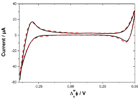
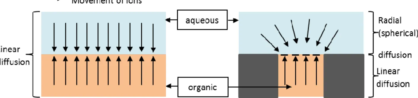
Page | 12 Electrochemistry at the ITIES has been frequently used as a sensing tool, as it allows non-redox active molecules to be detected, which may not possible with other analytical electrochemical sensing methods. Progress has been made to increase sensitivity, such as using microscopic ITIES and optimising hydrodynamic conditions in order to improve mass transport. Mass transport is the rate at which an analyte can get from the bulk solution to the position where it can be detected. The faster the rate, the higher the sensitivity. The rate of mass transport is affected by the diffusion profile of ionic species at the ITIES. As can be seen in Figure 1.5, the diffusion profile of the micro-ITIES has an asymmetric profile, versus a linear diffusion profile at macro-ITIES. The radial diffusion from the aqueous phase to the organic phase in the micro-ITIES generates a faster mass transport (as opposed to linear diffusion), thus giving a higher sensitivity, consequently allowing detection limits in the range of tens of nM [28]. Furthermore, using cyclic voltammetry and an array of nano-ITIES resulted in the detection of propranolol at values 5 – 10 times lower than the limit of detection achieved at the larger micro/macro interfaces [29]. Nano-ITIES have a diffusion profile similar to that of micro-ITIES and give a better electroanalytical response, as, under proper geometrical conditions, the array can be treated as a sum of individual ITIES, thereby maximizing the mass transport and thus greatly improving sensitivity.
Figure 1.5: Linear diffusion profile in both directions at Macro-ITIES (left) Vs Radial diffusion into the pore and linear diffusion within the pore at Micro-ITIES (right).
On the other hand, selectivity is a qualitative parameter, with high selectivity allowing the detection of very specific target molecules in a complicated medium such as water, sediment, soil and biota. In the field of environmental analysis, these target molecules can be emerging
pollutants. These are not necessarily new chemicals, rather chemicals that have just been discovered in the environment as a result of improved analytical detection techniques.
Page | 13 Thus these compounds need to be identified and their threat to both the environment and human health examined. In the pharmaceutical industry, assessing stereoselectivity in drug metabolism is highly important in order to produce safe, effective drug treatments. A technique with a very high degree of selectivity is needed to analyse racemic drugs and then eliminate the unwanted isomer. Recent developments to improve selectivity at the ITIES include the coupling of it with other analytical techniques, for example spectroscopy techniques, and using supported liquid membranes [15]. Using a porous membrane to support the ITIES has resulted in greater mechanical stability, which can help overcome limitations of linear diffusion of species and instability at the macro-ITIES. Matsui et al. studied the ion transfer of creatinine at a polarized nitrobenzene/water interface. A dialysis membrane covered the interface to prevent possible interference from urine proteins, while determining creatine in urine [30]. Furthermore, the modification of the ITIES can improve selectivity, by impacting the transfer of the analyte ions across the LLI. Modification via the assembly of particles and films at the interface is described in the following section.
1.1.5 Particle assembly at the ITIES
The ITIES has many advantageous properties from an electrochemical point of view. These include relative low cost, simple set up and short response time. The ability of the ITIES to be highly reproducible (due to its defect free nature) and healing (which allows self-assembly errors to be rapidly corrected), allows the self-assembly of a large variety of solid particles at the interface resulting in interfacial modification [31]. Certain materials can assemble automatically at the liquid-liquid interface, however for others electrochemistry at the ITIES acts as a driving force for the deposition of the materials at the interface. This can either occur ex situ (the material is first formed, then deposited) or in situ (the deposit forms during the interfacial reaction). Typical materials that can be assembled or deposited at the interface include phospholipids, organic polymers, carbon and metallic nanomaterials, as well as silica nanoparticles [32–35].
Single and multi-walled carbon nanotubes, graphene and graphite flakes can assemble at the liquid-liquid interface under proper conditions and due to their conductive properties they can improve chemical reactions and electron transfer kinetics by acting as conductive rafts [36– 38]. Kane et al. used surfactants to direct single-walled carbon nanotubes (SWNTs) to the LLI.
Page | 14 These SWNTs can transport enzymes to the interface and enhance the rate of catalysis by almost 3 orders of magnitude compared with enzymes alone [39]. Dryfe et al. deposited Pd and Au nanoparticles on a graphene monolayer, which had been assembled at the LLI. Metal deposition then occurred spontaneously or via an electrochemically-controlled process [40]. Furthermore, Dryfe and co-workers reported a process for the controlled assembly of liquid exfoliated graphene and SWNTs at the ITIES [41]. The electroactivity of these free-standing carbon films was studied and Pd nanoparticles deposited on them via in situ electro-deposition at the liquid-liquid interface.
Metal deposition can occur with Au, Ag, Pd and Pt and can be in the form of nanoparticles or films. Gold nanoparticles have been injected onto the interface between [heptane + 1,2 – Dichloroethane] and water and formed a self-assembled monolayer surface coverage, which exhibits reflectance and electrical conductance [42]. Samec et al. deposited mercaptosuccinic acid-stabilised gold nanoparticles at the polarizable water and 1,2 – Dichloroethane interface, under potential controlled conditions. The gold nanoparticles, initially suspended in the aqueous phase, achieved reversible interfacial adsorption at the ITIES, under controlled Galvani potential difference [43]. Furthermore TiO2nanoparticles have been assembled at the
polarizable interface between water and 1,2 – Dichloroethane, upon applying a potential bias [44,45].
Electrochemically induced interfacial adsorption at the ITIES has also been reported for amphiphilic ions, proteins and dendrimers. Amphiphilic molecules, e.g. phospholipids, have been adsorbed under applied potential conditions and studied via electrocapillary curve measurements [46–48]. Cyclic voltammetry was used to follow the adsorption of phosphatidylcholine phospholipid (which was present in the organic phase) and its interactions with ionic species that were present in the aqueous solution (K+, H+, Fe2+, Fe3+,
IrCl62−, IrCl 6
3−). A triangular signal in the cyclic voltammogram indicated the adsorption of the
phospholipid. Contact angle measurements showed that values increased with the polarization towards more positive potential, when phospholipid adsorption occurred [49]. Dendrimers are large, multicharged species, which have applications as drug carriers [50], molecular gates [51] and soft templates [52]. At the electrified liquid-liquid interface, however, dendrimers with growing size and charge exhibit complex behaviour, thus electrochemistry at the ITIES has been used to study them [53,54].
Page | 15 Similarly, interfacial adsorption of biomolecules has been observed for insulin and hen egg-white lysozyme [55], as well as haemoglobin [56]. Haemoglobin not only adsorbed at the interface but due to its positive charge, interacted with the anionic part of the organic phase supporting electrolyte, facilitating its transfer by decreasing its Gibbs energy of transfer. The assembly of silica materials at the LLI has found applications in a wide range of scientific disciplines due to their attractive physicochemical properties. A description of silica compounds, along with the synthesis of silica nanoparticles and their applications, are discussed in detail in the following section.
1.2
Nanoparticles
Nanoparticles are defined as three-dimensional nanomaterials whose size spans the range between 1 and 100 nm in at least one dimension. Consequently, these particles show physical, chemical and biological properties that differ from those observed in their bulk or molecular counterparts [57,58].
Page | 16 Furthermore, as a result of this size range, nanoparticles also fall into the domain of colloidal particles. Colloid science is the study of colloid particles with a size or with one dimension between 1 nm and 1 µm [60]. It attempts to explain and predict the properties of substances based on their dimensions and surface features. Colloidal particles are sufficiently small to be unaffected by gravity but large enough to show differences from the properties of true solutions. They are made of associations or colonies of ~103 – 109 atoms, which are arranged
in a crystalline or amorphous structure. Colloidal dispersions are defined as a multi-phase system where particles are dispersed/suspended in a solution. These dispersions can be stabilized against coagulation by steric effects or electrostatic repulsion. In this case, the stable dispersion of solid colloidal particles in the liquid phase is referred to as a sol [57,60]. Nanoscience and nanotechnology have become increasingly popular in recent years due to the benefits these areas have brought to research topics and their applications, in sectors such as information technology, medicine, energy, food and environmental science. However some nanomaterials are not without their disadvantages. Due to their small size, they have been found to have an adverse impact on health when inhaled and may have a negative, toxicological effect on the environment [58]. Conversely, silica nanoparticles have always been regarded as safe and authorized for use as an ingredient in food, due to the natural presence of silicon in the environment. Furthermore silica has been widely studied for decades and has applications in many fields. Silica compounds are amongst the most commonly used materials to synthesise nanoparticles due to their attractive properties such as physical rigidity, high thermal stability and negligible swelling in both aqueous and organic solutions [61].
1.2.1 Nomenclature and physicochemical properties of silicon and silicon
containing compounds
Silicon (Si) is the second most abundant atom in the earth, after oxygen. It rarely occurs as a pure element in nature, but more frequently combines with other oxide materials in the environment. When combined with oxygen it is given the IUPAC name silicon dioxide (or silica), SiO2, which forms amorphous and crystalline compounds such as quartz, flint, opal. Thus silica played an important role in civilization as it was used to make tools and pottery. The combination of silica with hydroxides generates silicic acid, with the general formula [SiOx(OH)4−2x] n, which is found dissolved in the oceans.
Page | 17 Silica is also found in living organisms like sponges, grasses (which use it to stiffen stems for holding fruit) and animals (who use it to form bones, hair and teeth) [62–65]. Furthermore, SiH4 is called silane and silicates are anionic species containing a silicon atom, e.g. SiO44−.
Silanols refer to a silicon atom which has at least one OH group attached. Organosilicon compounds occur when there is a covalent bond between a silicon and carbon atom. Finally, silicon alkoxides, or alkoxysilanes, are compounds of silicon and alcohol with the general formula Si(OR)4, with R representing an organic group.
Table 1.1: Physiochemical properties of silicon atom [66]
IUPAC name Silicon CAS no. 7440-21-3
Discovery date 1824 Melting point 1414 °C, 1687 K
Discovered by Jöns Jacob Berzelius Boiling point 3265 °C, 3538 K
Allotropes Amorphous,
crystalline Atomic mass 28.085
Atomic number 14 Density 2.3296 g cm-3
Key isotopes 28Si, 30Si State at 20°C solid
Page | 18
1.2.2 Silica nanoparticles
As mentioned previously, silica is found in nature in its crystalline form (as quartz sand), however amorphous silica is industrially manufactured, in forms such as silica gels, precipitated silica, fumed silica and colloidal silica. Silica gel is most commonly found in paper packets and used as a desiccant to absorb moisture and so avoid degradation of some goods. Precipitated silica products are used as thickening agents and anti-corrosion pigments to improve performance and sustainability of coating, paints, inks, etc. Fumed silica, like silica gel, acts as a desiccant and is also used as a thickening and anti-caking agent in powders. It is also found in products like toothpaste, acting as a light abrasive. Colloidal silica is the stable dispersion of solid silica particles and so is in liquid form, as opposed to powder. All of these forms of silica particles consist of an amorphous network of silicon and oxygen and are non-crystalline (they do not have long range order). They can all be produced from silica ore using various synthetic routes, thus ultimately producing particles with varying sizes, shapes, uniformity, sphericity and stability. Colloidal silica nanoparticles which are used in this research can be prepared from silica ore via ion exchange of sodium silicate, or direct oxidation of silicon, or by milling and peptization of silica gel or fumed silica, or more commonly via a Sol-gel process, which involves the hydrolysis and condensation of silanes. It is with the Sol-gel synthesis that nanoparticles of a controlled and uniform shape and size are obtained, as reaction parameters such as the solvent, catalyst, concentrations, temperature and reaction time are controlled [60,67,68]. The process will be described in further detail in the following section.
Table 1.2: Starting materials and preparation methods for colloidal silica [67]
Starting material Preparation method
Sodium silicate Ion exchange
Silicon Direct oxidation
Silica gel/fumed silica Milling and peptization
Page | 19
1.2.2.A
Dense Silica Nanoparticles (DSNs)
The Sol-gel process originates from the so-called Stöber process. In 1968, Stöber et al. established a method of synthesis of silica particles with controlled growth and a uniform size (between 0.5 - 2 µm), with narrow particle size distributions [69]. These monodispersed silica colloids were prepared by hydrolysis of alkyl silicates and subsequent condensation of silicic acid in alcohol, with ammonia as a catalyst. Many studies have since been performed in this area in order to have a greater understanding of the processes occurring during the reaction, which can thus lead to a more efficient and controlled synthesis of silica nanoparticles. The Sol-gel process involves two distinct steps: (i) hydrolysis and (ii) condensation.
𝑆𝑖𝑂𝑅4+ 𝐻2𝑂 𝐻𝑦𝑑𝑟𝑜𝑙𝑦𝑠𝑖𝑠→ 𝑆𝑖(𝑂𝑅)3𝑂𝐻 + 𝑅𝑂𝐻 𝑆𝑖(𝑂𝑅)3𝑂𝐻 + 𝑆𝑖(𝑂𝑅)3𝑂𝐻
𝐶𝑜𝑛𝑑𝑒𝑛𝑠𝑎𝑡𝑖𝑜𝑛
→ (𝑂𝑅)3𝑆𝑖 − 𝑂 − 𝑆𝑖(𝑂𝑅)3+ 𝐻2𝑂
During hydrolysis, a hydroxyl ion becomes attached to the silicon atom of the alkoxysilane species. Two of these products react together to generate a siloxane [Si – O – Si] bond, liberating water or alcohol in the process. This condensation step is catalysed by the presence of a base and as the reaction continues, a large network of silicon-containing molecules is generated by the process of polymerization, thus forming a silica nanoparticle with a dense amorphous core of silica, as shown in Figure 1.8.
Page | 20 The size of the resulting particle depends on the type of silicon alkoxide and alcohol used during the reaction [61,71]. Typically the particle size increases with increasing chain length of the alcohol and also the hydrocarbon chain length of the alkyl silicates [72]. Furthermore, research on varying the temperature by Tan et al. showed a decrease in temperature resulted in monodisperse particles with a size of ~2 µm [73]. The effect of the catalyst concentration was studied by Ibrahim et al. who demonstrated that particle size increases with ammonium concentration [62].
Monodispersed silica nanoparticles synthesized with a specific particle size and narrow distribution by the Sol-gel process have various applications in research. Sacks and Tseng investigated the sintering behaviour of these colloids, which produced highly ordered compacts [74]. Unger et al. used them as a packing material for capillary chromatography [75]. They have also been investigated as a material from which to fabricate photonic crystals of 3D periodic structure [76,77]. As mentioned in Section 1.2, due to the low toxicity and biocompatibility of silica nanoparticles, they are used in medical, biological and chemical industries [78,79]. Functionalisation of the surfaces of the nanoparticles has allowed their range of applications to spread and dye-doped silica nanoparticles have been designed for potential uses in the biomedical field and also coating applications [80,81]. Self-assembly of the colloids have generated patterns which have potential applications in optical, magnetic and electronic devices as photonic band gap materials. Furthermore self-assembly at the liquid-liquid interface has gained popularity and stabilised 2 or 3D silica sphere structures have been self-assembled at the LLI to fabricate 2 or 3D ordered structures [82].
1.2.2.B
Mesoporous Silica Nanoparticles (MSNs)
A desire for the use of nanoparticles as catalysts and sorption media required nanoparticles with high surface area [83]. This resulted in the formation of silica nanoparticle with pores, thus giving them attractive features such as large surface areas, tunable pore sizes and volumes and stable structures with well-defined surface properties [84]. The pores of these mesoporous nanoparticles range in size from ~2 – 50 nm, as described in Figure 1.9.
Page | 21 Figure 1.9: Distinguishing between micro-, meso- and macro- pores according to size, with examples. Image adapted from Owens et al. [85]
The first mesoporous silica was discovered in 1992 by Kresge and co-workers [86]. They proposed a liquid-crystal ‘templating’ route to generate mesopores in the silica. Highly ordered materials with ~3 nm sized pores were obtained from silicate gels and quaternary ammonium surfactants of differing chain lengths. The alignment of pores was either hexagonal (MCM-41) or cubic (MCM-48) [87]. The nomenclature MCM represents Mobil Composition of Matter, as these mesoporous silica nanoparticles were first developed in the labs of the Mobil Corporation [88]. However, it wasn’t until 2003 that Lin and co-workers were able to control the morphology and generate nanosized mesoporous particles that could be stabilised as colloidal solutions. They synthesized functionalized mesoporous silica nanospheres with an average size of 200 nm and pore diameter of 2.3 nm [84]. Since then many different procedures have been developed to synthesise mesoporous silica nanoparticles, in the shape of spheres or rods, with mostly cylindrical shaped pores which vary in the level of order of molecular organisation [89–92]. The inorganic silica framework can have a well ordered hexagonal, disordered or cubic pore structure, which is determined by the synthesis conditions applied [88].
Page | 22 Figure 1.10: Schematic of MSN synthesis using a surfactant templated sol-gel approach [93] The general synthesis route for uniform mesoporous silica nanoparticles is based on a surfactant templated sol-gel approach as shown in Figure 1.10. Thus, hydrolysis and condensation of the alkoxysilane occurs in an aqueous alkaline solution, similar to the procedure for dense silica nanoparticles, but in the presence of an ammonium surfactant. It is the presence of the surfactant that creates the porosity in the material. The first step is to dissolve the surfactant in water, add the base and alkoxysilane and heat the mixture to allow the polymerization of the silica [88]. During this process, the surfactant forms micelles with a hydrophobic interior and hydrophilic surface. The silica network grows around these micelles, resulting in particles with surfactant and solvent filled channels [94]. Compared with the procedure for dense silica nanoparticles, an extra step is required here to remove the surfactant template and so expose the pores.
Page | 23 Methods of extraction include calcination and solvent extraction, ozone treatment, reflux or sonication and centrifugation with an acidic mixture (ion exchange), depending on the nature of the mesoporous material [95,96]. The resulting nanoparticles are generally dispersed in a liquid medium, however template removal greatly effects their dispersity and so they tend for form large aggregates which greatly reduces their benefits [95].
As with the dense nanoparticles, synthesis conditions, for example pH, temperature, surfactant and co-solvent, can be manipulated to control the size and shape of the nanoparticles that are produced. The pH of the precursor solution is influential during the hydrolysis step of the synthesis. Hydrolysis can take place in acidic or basic solutions but is very slow at neutral pH. Furthermore, silica is only negatively charged at pH values above its isoelectric point of pH 2. The silica needs to be negatively charged in order to have an electrostatic interaction with the positively charged surfactant and assemble to form the silica-surfactant nuclei. The greater the pH the larger the amount of mesoporous silica nanoparticles generated, thus Ding & Su determined pH 2.6 to be optimal in their synthesis [97]. Möller et al. showed that if the common base sodium hydroxide (NaOH) is replaced by triethanolamine (TEA), then the reaction can be run at a lower pH with the condensation step being influenced by the complexation effect of TEA and thus generating discrete mesoporous nanoparticles with narrow particle size distribution [83]. The groups of Vansant and Ogawa varied the surfactant concentration, which allows control over the diameter and volume of pores, and thus of the surface area of the product material [98]. Increasing the amount of surfactant leads to increases in total pore volume and hence particle surface area, but with individual pore diameters remaining unchanged [99]. Vansants group also determined that varying the amount of ammonia used relative to surfactant concentration allowed tuning of the pore diameter; additional ammonia leads to pores with greater diameters, but with a corresponding decrease in total pore volume and particle surface area. Furthermore, they investigated the effect of the time allowed for the reaction to proceed on particle porosity, with greater reaction times leading to increases in total pore volume and particle surface area. Longer reaction times also lead to increases in overall silica particle size and decreases in the uniformity of the size distribution [98].
Page | 24 MSNs have two different surfaces – an interior channel surface as well as the exterior particle surface. Modification of these surfaces has allowed the range of applications of mesoporous nanoparticles to widen. There are two main strategies for modifying the surface of the nanoparticles: postsynthesis functionalization (grafting) [100,101] and in situ functionalization (co-condensation) [102–104]. Grafting selectively functionalises the exterior surface of a post synthesized nanoparticle. It is based on a condensation reaction between an organoalkoxysilane and free and geminal silanol groups (which have two hydroxyl groups attached to one silicon atom) on the silica surface and openings of the pores [105,106]. Following this, cross linking or click chemistry based reactions can easily bind the target analytes (proteins, DNA) with the grafted functional groups (-NH2, -COOH, -SH) [88,107].
Organosilica materials (a siliceous material with silicon – carbon bonds) can be used which allow the synthesis of hybrid materials, incorporating carbon groups into the inorganic silica matrix. On the other hand, co-condensation is a direct synthesis method which generates monodisperse, multi-functionalised MSN, with better bonding between the organoalkoxysilane and the pore walls, thus giving a more homogenous distribution of organic groups throughout the pore structure. The co-condensing agent (organoalkoxysilane) is added to the aqueous surfactant and alkoxysilane solution during condensation to control the shape of the resulting mesoporous silica nanoparticles, as outlined in Figure 1.11. The characteristics of the co-condensating agent, for example concentration, molecular size and hydrophobicity/hydrophilicity, determine the ability of the co-condenser to influence the stabilization of the micelles during MSN formation. This ultimately controls functionality, shape and size of the MSN produced [92,104,108].
Figure 1.11: Schematic of alkoxysilanes (TEOS) with organoalkoxysilanes (RTES) and micelle forming surfactant, in a co-condensation reaction, adapted from reference [108]
Page | 25 Various techniques are used to characterize dense and mesoporous silica nanoparticles [89– 91,104,108]. Scanning electron microscopy (SEM) and transmission electron microscopy (TEM) are used to determine sample morphology and microstructure, allowing the measurement of particle diameter and distance between pores (for MSN) within a particle. Dynamic light scattering (DLS) also allows particle morphology and size to be recorded. X-ray powder diffractometry (XRD) shows the long range order of materials, i.e. their structure and crystallinity. Gas adsorption volumetry of MSNs characterizes the porous materials using two different equations. The Brunauer-Emmett-Teller (BET) method calculates the specific surface area of porous materials, while the Barrett, Joyner and Halenda (BJH) method derives pore size distribution [109]. With regards functionalized silica nanoparticles, additional techniques are used to characterize the presence, connectivity and surface coverage of the functional groups on the silica. Infrared (IR), Ultraviolet-visible (UV/Vis) and Raman spectroscopy are used to confirm the presence of the functional groups and template. Nuclear magnetic resonance (NMR) spectroscopy studies the incorporation of the organic groups, specifically the connectivity of the functional organic groups, to the silica framework. Thermogravimetric analysis measures the weight change in a sample relating to desorption of template, thus quantifying the amount of template that was incorporated. It can also be used to measure the surface coverage of functional groups.
The combination of excellent physical and chemical properties, large surface area and ability of the surface to be functionalized gives mesoporous silica nanoparticles a huge range of applications, in fields such as catalysis [110], pollutant adsorption [111], chemical sensors [112] and electroanalysis [113]. Furthermore, they have been used in biochemistry as carriers for the controlled release delivery of drugs, biocides and proteins [84,114]. There is a growing interest for the use of silica based porous materials at the LLI due to their favourable adsorption kinetics and selectivity [96,115]. Silica nanoparticles themselves do not have any sensing signal but serve as an aid to enhance the selectivity and preconcentration of ionic species at the interface and thus their transfer across the ITIES. This ability to detect ionic species is of major benefit in both environmental monitoring and clinical diagnosis. The sensing of synthetic organic molecules, such as drug molecules and pollutants, is of significant interest. Functionalized silica nanoparticles can be used as a base on which a target molecule (e.g. drug molecule) can be imprinted and used to improve selectivity of detection in systems such as the liquid-liquid interface.
Page | 26
1.3
Molecular imprinting
The field of molecular imprinting has gained a lot of attention in recent years as a result of its attractive properties of selectivity, stability and low cost. Molecular imprinting is defined as the arrangement of a cross-linked silica or polymer matrix around an imprint molecule, interacting via covalent or non-covalent interactions with chosen functional groups on the silica or polymer. Upon removal of the imprint molecule, a cavity with a specific size and shape is exposed, with the functional groups on the surface which give it a molecular memory, thus allowing it to selectively rebind to the target imprint molecule [116,117].
Figure 1.12: Schematic of the principle of Molecular Imprinting [118]
Molecular recognition is the underlying principle for biological processes such as that between antibodies and their target antigens, enzymes with their substrates and hormone receptors with their hormones [117]. This ‘lock and key’ concept allows specialized structures to recognize and bind with their target molecules with a high affinity and selectivity. As a result these biomacromolecules have numerous applications in medicine and biotechnology. ELISA (enzyme linked immunosorbent assays) use a specific biological recognition mechanism to detect and quantify targets. Antibodies have been used to treat infections, diseases and more recently cancer. Unfortunately though, these natural mechanisms have their disadvantages. Lack of stability, degradation, low abundance and problems with integration in industry have meant that researchers have been looking for alternatives [117]. Consequently, artificial structures have been synthesized from silica and polymers, that are tailor made with high selectivity.
Page | 27
1.3.1 History of Molecular Imprinting
The concept of molecular imprinting evolved after investigations by the botanist Tswett in 1906, for its usefulness in purifying and analysing single compounds from crude mixtures. Tswett carried out research into plant pigments and invented adsorption chromatography. Research during much of the 1900’s was focused on developing raw materials and techniques for use in chromatography [119–121]. The use of silica as a material in chromatography was first noted by Polyakov in the early 1930’s. He investigated the effect of organic additives (benzene, toluene and xylene) on the structure of silica pores, further observing that after the synthesis, the quantity of additive re-adsorbing depended on the structure of the additive present during silica drying [122]. The explanation for this preferential uptake can be explained by the additive generating a templating effect and thus the concept of molecular imprinting was born. Further research by Polyakov gave more detail of this selective molecular recognition phenomenon [123,124].
The link between the biological antibody-antigen relationship and the chemical silica-additive interaction was made by Linus Pauling and Frank Dickey in 1949, based on results of experiments carried out by Dickey. At that time, Pauling’s research was focused on the origin of the selectivity of antibodies. Dickey synthesized what he called ‘specific adsorbents’ by mixing alkyl orange dyes with sodium silicate and glacial acetic acid. The polymerization of the silica around the dye molecules and their subsequent extraction, generated a cavity (imprint), which was able to preferentially rebind the template dye over the other dyes [125]. Dickey suggested two related processes that could explain what was occurring during the experiments and published them in a later paper [126]. The term ‘imprint’ was coined by Haldeman and Emmett, after they reinvestigated Dickey’s research and used the term to describe the micropores that were created in the adsorbent by the dye molecule used [121,127]. Unfortunately much debate ensued about the true mechanism occurring and limitations in stability and reproducibility of imprinted silica materials caused research in imprinting to shift away from silica and towards organic polymers [116,128]. After many years of research into the mechanisms occurring during imprinting with polymer imprinted materials, limitations were also observed and so, more recently, the use of silica has regained appeal. Thus a brief introduction on polymer imprinted materials will be discussed in section 1.3.3, including their limitations which are resulting in the drive of research back towards silica imprinted materials, discussed in section 1.3.4.
![Figure 1.1 Different models for the ITIES structure. Black solid lines correspond to potential distribution across the polarized liquid – liquid interface [13]](https://thumb-eu.123doks.com/thumbv2/123doknet/14725203.751882/16.892.107.812.581.780/figure-different-structure-correspond-potential-distribution-polarized-interface.webp)

![Figure 1.6: Summary of nanoparticles size, surface features, shapes and material [59]](https://thumb-eu.123doks.com/thumbv2/123doknet/14725203.751882/27.892.103.808.599.990/figure-summary-nanoparticles-size-surface-features-shapes-material.webp)