HAL Id: hal-01633795
https://hal.archives-ouvertes.fr/hal-01633795
Submitted on 14 Nov 2017HAL is a multi-disciplinary open access archive for the deposit and dissemination of sci-entific research documents, whether they are pub-lished or not. The documents may come from teaching and research institutions in France or abroad, or from public or private research centers.
L’archive ouverte pluridisciplinaire HAL, est destinée au dépôt et à la diffusion de documents scientifiques de niveau recherche, publiés ou non, émanant des établissements d’enseignement et de recherche français ou étrangers, des laboratoires publics ou privés.
3D imaging of a dislocation loop at the onset of
plasticity in an indented nanocrystal
Maxime Dupraz, Guillaume Beutier, Thomas W. Cornelius, Guillaume Parry,
Z. Ren, Stéphane Labat, Marie-Ingrid Richard, Gilbert Chahine, Oleg
Kovalenko, Marc de Boissieu, et al.
To cite this version:
Maxime Dupraz, Guillaume Beutier, Thomas W. Cornelius, Guillaume Parry, Z. Ren, et al.. 3D imaging of a dislocation loop at the onset of plasticity in an indented nanocrystal. Nano Letters, American Chemical Society, 2017, 17 (11), pp.6696 - 6701. �10.1021/acs.nanolett.7b02680�. �hal-01633795�
3D imaging of a dislocation loop at the onset of plasticity in an indented
nanocrystal
Authors
M. Dupraz1,*, G. Beutier1, T.W. Cornelius2, G. Parry1, Z. Ren2, S. Labat2, M.-I. Richard2,3, G. A.
Chahine3, O. Kovalenko4, M. De Boissieu1, E. Rabkin4, M. Verdier1, O. Thomas2
1. Univ. Grenoble Alpes, CNRS, SIMAP, F-38000 Grenoble, France
2. Aix Marseille Univ., Université de Toulon, CNRS, IM2NP UMR 7334, F-13397 Marseille Cedex 20, France
3. ID01/ESRF, 71 Avenue des Martyrs, CS40220, F-38043, Grenoble Cedex 9, France
4. Department of Materials Science and Engineering, Technion – Israel Institute of Technology, 32000 Haifa, Israel
* Current address: Swiss Light Source, Paul Scherrer Institut, CH-5232, Villigen PSI, Switzerland
E-mail: [email protected]
Abstract
Structural quality and stability of nanocrystals are fundamental problems that bear important consequences for the performances of small-scale devices. Indeed, at the nanoscale, their functional properties are largely influenced by elastic strain and depend critically on the presence of crystal defects. It is thus of prime importance to be able to monitor, by non-invasive means, the stability of the microstructure of nano-objects against external stimuli such as mechanical load. Here we demonstrate the potential of Bragg Coherent Diffraction Imaging for such measurements, by imaging in 3D the evolution of the microstructure of a nanocrystal exposed to in situ mechanical loading. Not only could we observe the evolution of the internal strain field after successive loadings, but we also evidenced a transient microstructure hosting a stable dislocation loop. The latter is fully characterized from its characteristic displacement field. The mechanical behavior of this small crystal is clearly at odds with what happens in bulk materials where many dislocations interact. Moreover this original in situ experiment opens interesting possibilities for the investigation of plastic deformation at the nanoscale.
Keywords: nanocrystal, nanoindentation, dislocations, coherent diffraction imaging
Understanding the stability and the mechanical response of micro and nanocrystalline materials is a long standing investigation topic, strongly driven since the 1970s by the length scale reduction effort for functional devices in microelectronics. A key parameter is the density of crystalline defects and/or the ability to nucleate them. With a decreasing sample size, larger elastic strain can be sustained. The latter is a consequence of the scaling of the energy balance between the volumetric strain energy being relaxed by dislocation nucleation / expansion and their energy cost, as well as the lack of dislocation sources in small samples. The scaling down in length scale also reveals the intrinsic discrete nature of the strain ()
response (jerky behavior) 1 since each dislocation carries a quantum of deformation (the
magnitude b of the Burgers vector b). For example, a single dislocation shearing a L = 100 nm gold crystallite brings a plastic strain = b/L ≈ 0.2%, already reaching the engineering yield strain as defined for macroscopic samples. As a consequence, when comparing the response at the onset of plasticity in bulk and small crystals, the transition between the elastic and plastic regimes occurs in a larger strain range in sub-micrometric crystals 2. Dedicated
quantitative mechanical measurements have been developed to characterize the size effect, using contact mechanics (nanoindentation) 3,4 or traditional uniaxial loading 5,6. Strength
evolution with size supports the phenomenological ‘smaller is stronger’ statement 4,5,
observed for face-centered cubic (fcc) 4, body-centered cubic (bcc) and hexagonal
close-packed (hcp) metals 7. However, the microstructure of the sample (residual strain field and
defect content) is often overlooked, although it is a key parameter to understand the large experimental scattering of mechanical response for a given sample size 8. A full picture of the
effect of size on strength can therefore only be studied by investigating the relationship between the microstructure and the mechanical response 9.
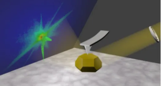
In this work we follow the evolution of the microstructure (elastic strain and defects) of a gold sub-micrometric crystal during the very first stages of its indentation. We use Bragg Coherent Diffraction Imaging (BCDI) to obtain quantitative 3D images of its structure at the nanoscale. BCDI is a lens-less microscopy technique providing real space images from the algorithmic
inversion of high-resolution reciprocal-space data measured with a coherent X-ray beam 10
(Fig. 1). In Bragg geometry, the retrieved image is a complex field encoding the electronic density (r) (in its modulus) and the displacement field u(r) projected onto the diffraction vector (in its phase) 11,12. BCDI has been shown to be very sensitive to the presence of crystal
defects such as dislocations 13–18 . Moreover, most simple dislocation configurations in fcc
metals can be identified from their signatures in 3D Bragg diffraction patterns and in the reconstructed real space images 19,20. The contrast of the dislocation configurations depends
on the selection of the Bragg diffraction vector: the principle is somehow analogous to that in Transmission Electron Microscopy (TEM) 21–23 but enriched by the available quantitative
displacement field.
The crystals used for this experiment were gold crystals obtained by solid-state dewetting on a sapphire substrate 24,25. On top of its experimental convenience (gold is chemically inert and
a strong X-ray scatterer), gold is well representative of fcc crystal plasticity at room temperature. Most crystals present well defined {1 0 0} and {1 1 1} facets with rounded edges, and a few percent of them resemble closely their thermodynamic equilibrium (so-called
Winterbottom) shape 26. These candidates were selected by Scanning Electron Microscopy
(SEM) (Supporting Information S1).
The BCDI measurements were performed by recording the intensity distribution in the vicinity of the specular 1 1 1 Bragg reflection in 3D: the sample was rocked across the Bragg peak and the diffraction patterns were collected with an area detector 27. Experimental details,
including the algorithmic procedure used for recovering the direct-space images are given in the Supporting Information S3. The reconstructed direct-space images have a voxel size of 7.2 x 8.5 x 7.6 nm3. The experimental resolution is of the order of 13 nm, as determined by
the phase retrieval transfer function (PRTF) 28.The phase map obtained from the inversion of
the BCDI data at the 1 1 1 Bragg reflection encodes the displacement field along the [1 1 1] direction, which is normal to the substrate surface (labeled z, increasing from the interface with the substrate toward the top free facet). The strain component εzz=∂ uz
∂ z comes thus
straightforward (bearing in mind that the reference εzz=0 is arbitrarily chosen at the center of mass of the Bragg peak).
The BCDI measurements of the pre-selected crystals in their ‘as-received’ state revealed that most of them (5 out of 7 measured) were severely faulted despite their ‘pristine-like’ appearance. This faulting may be associated with the coherent twin boundaries parallel to the substrate sometimes observed during the solid state dewetting of thin films 29,30. The
remaining two displayed a 3D Bragg pattern close to the one expected for a defect-free and weakly strained crystallite, with straight fringed streaks along the facet directions (Fig. 2a-b). One of them was chosen for the indentation test. Its electron density, reconstructed from the diffraction pattern (Fig. 2c), appears very smooth and strongly faceted with {1 0 0} and {1 1 1} planes connected with rounded edges. Both the shape and dimensions of the crystallite (550x550x275 nm3) bear a strong similarity to the SEM data (Supporting Information S1). In
the pristine state, the reconstructed phase field is continuous; denoting the absence of crystal defect, but the derived strain field εzz is unexpectedly heterogeneous, with an amplitude spanning ~ 4x10⁻³ (Fig. 2d). Compressive strain is observed at the substrate/particle interface,
which can be ascribed either to the partially relaxed in-plane tensile thermoelastic strain induced during the fabrication process of the particles 31, or to the interface stress caused by
Fig. 2 (qy,qz) (a) and (qx,qy) (b) slices of the 3D 1 1 1 Bragg peak for the pristine island. (c)
Isosurface of the reconstructed electron density drawn at 25% of the maximum density. (d) Isosurface of the strain drawn for εzz < 7.10-4 (blue) and for ε
zz < 7.10-4 (orange)
In situ mechanical stimuli were applied with a dedicated compact AFM (SFINX) 33,34 mounted
on the diffractometer. The AFM tip was centered on the top (1 1 1) facet of the crystallite using tapping mode imaging prior to indentation. Indentation forces are in the few 100 nN range consistent with atomistic calculations for the onset of dislocation nucleation in Au crystallites
35,36. Consecutive indentations with increasing loads were performed on the same crystallite,
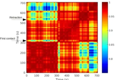
with intermediate recording of the 3D Bragg pattern. During indentation at a constant force rate of approximately 10 nN/s, a slice of the Bragg pattern was monitored at a 1Hz rate. If persistent changes in the pattern were noticed, the tip was withdrawn to proceed with the recording of a 3D diffraction pattern. Cross-correlation of the monitoring frames (Fig. 3) displays dips in the cross-correlation denoting changes of the crystal microstructure, and it reveals if the latter are persistent or not.
The first two indentations corresponding to loading ramps of up to 320 nN and 380 nN, respectively, did not lead to remarkable changes in the diffraction patterns and their direct-space reconstructions. Some transient changes appeared during the second loading but were not persistent over a few seconds lapse. Defects might have been nucleated but their signature quickly vanished, probably exiting to the free surfaces or to the substrate interface as it will be discussed later. In contrast, during the third loading (applied force around 560 nN) a clear and persistent changes in the cross-correlation (Fig. 3) mark the nucleation of a stable defect within the crystallite.
Fig. 3 Cross-correlation of diffraction patterns taken during the third indentation. Each
diffraction pattern is a single frame recorded at a fixed rocking angle of 0.035° above the peak of the rocking curve. The cross-correlation highlights the occurrence of plastic events. Most of them are transient (t = 320 s for instance) while others are persistent over a few seconds (t = 625 s). The final state, which contains the dislocation loop, correlates best with the state at t = 500s.
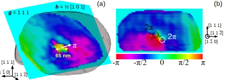
Very interestingly, the reconstructed real space data after the third loading/unloading iteration clearly indicates the presence of a dislocation loop inside the crystal (Fig. 4). This is evidenced in both the density and phase data by a common line contour: it appears in the former as a region of lower density and in the latter as a sharp phase boundary surrounded by a 2π phase vortex (Fig. 4b) 20. Within our resolution, the loop appears planar and is
contained in a (1 0 1) crystallographic plane, and has a roughly circular shape with a diameter of 65-70 nm. It is located at around 100 nm above the interface with the substrate and is roughly in the middle laterally (see Supporting Information S1, Fig. S1c). The phase is homogeneous inside the loop and the phase jump across the dislocation is equal to π (Fig. 4a). The (1 0 1) crystallographic plane orientation and the π phase shift are sufficient criteria to allow the unambiguous identification of the loop as a prismatic loop with Burgers vector b =
a/2[1 0 1] 20. This type of dislocation configuration is characterized by a Burgers vector
perpendicular to the plane of the loop and consists of dislocation segments on two slip planes that share the same Burgers vector 37,38. The dislocation loop and its Burgers vector define a
prism on which the dislocation can glide conservatively. The phase gradient is significant in the vicinity of the loop only, within a distance of the order of the loop diameter, as expected for such configuration 37. Altogether, the phase data is very consistent with the one around
Fig. 4 Reconstruction of the phase field after the third indentation evidences a prismatic
dislocation loop. (a) Reconstructed experimental φ1 1 1 phase fields in the (1 0 1) plane normal
to the glide cylinder of the prismatic loop. The electron density drawn at 21% of the maximum electron density is superimposed in transparency to indicate the position of the loop. (b) Reconstructed φ1 1 1 phase field in the (1 -1 0) plane intercepting the prismatic loop in two loci.
Prismatic loops are common dislocation configurations generally considered as ‘debris’ of plastic activity, and are often overlooked because of their small size, small residual strain field and difficulty to distinguish them in entangled assemblies of dislocations in TEM 39.
Nevertheless, they are of fundamental importance to explain salient features of crystal plasticity and dislocation nucleation, and have been recently proposed to explain initial hardening and avalanche effects at small length scale 40. If the local stress tensor promotes
the activation of one of their two slip system, prismatic loops can act as Frank-Read dislocation sources. Moreover, the punching out of prismatic loops to accommodate an imposed deformation is at the origin of the so called Geometrically Necessary Dislocation (GND) concept 41, e.g. around a non-deformable precipitate in a ductile matrix 42 or beneath
an indenter tip 3,42. In the latter case, atomistic simulations (in fcc, bcc, and hcp metals) detail
various surface nucleation processes that end by prismatic loop formation at the onset of plastic deformation 43–46. In a bulk crystal under loading, initial loops can move further away
from the plastic zone by gliding on their prism. In our nanocrystal geometry, depending on their location, they could either exit at the free surfaces or be absorbed at the metal-ionic crystal-substrate interface.
Increasing the final load in subsequent indentations by about a factor 2 (1.15 µN, 4th iteration)
and 4 (2.17 µN, 5th iteration) did not create major changes during the in situ recording of a
slice of the Bragg pattern (cross-correlation). The prismatic loop disappeared from the crystallite volume after the 4th iteration, and the reconstructed u
z displacement fields appear to
be very homogeneous suggesting that the strain field in the crystallite has been partially relaxed (Supporting Information S5).
As stated above, each Bragg reflection yields a single projection (uz) of the displacement field
u(r). To recover the two perpendicular components (ux, uy), we use a linear anisotropic elastic
continuum formulation to write the mechanical equilibrium of the crystallite containing dislocations and known boundary conditions 47. The reconstructed u
z field includes the
signature of the dislocation structure in all the volume, which combined with surface boundary conditions, is sufficient to give a unique solution of the displacement field. The problem is solved numerically using the Finite Element Method (FEM), see Supporting information S6. All
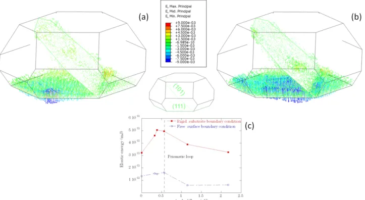
surfaces of the crystallite are treated as free surfaces (traction-free boundary condition), but for the mechanical behavior of the crystallite-substrate interface two extreme cases are considered: either non-penetrable interface ( ⃗u=⃗0 ) or free surface. Estimates of the complete displacement field allows to compute the loci of maximum principal strain within the particle, which is particularly useful to confirm the location of the dislocation loop and to study the strain at the particle-substrate interface (Fig. 5 a-b). We propose that the variation of maximum principal strain close to the interface results from defects storage and relaxation at the interface.
Fig. 5 Local maximum principal strain in the (1 0 1) plane intersecting the dislocation loop and
the (1 1 1) plane at the crystallite-substrate interface, obtained from the reconstructed displacement field and crystallite boundary condition by FEM in the pristine state (a) and after nucleation of the prismatic loop (b). (c) Evolution of the total elastic energy for consecutive indentations with increasing load.
It appears that after the first and second loadings, a strong discontinuity in strain is present close to the substrate at the bottom of the crystallite. This may be the result of dislocations being nucleated and quickly gliding towards the crystallite-substrate interface. After the third iteration, the prismatic loop is well evidenced together with a remaining strain concentration at the substrate interface. The fact that the prismatic loop is stabilized roughly at the mid-height of the crystallite could result from a repulsive field arising from defects stored at the crystallite-substrate interface. The weak gold-sapphire interface probably allows for some thermally activated atomic rearrangements that relax the displacement components of some stored defects. The dislocation loop disappeared during the 4th cycle of loading/unloading, probably
pushed by the load toward the substrate interface which acts as a sink. No new defects were detected after the 4th and 5th iterations, which is a manifestation of the stochastic nature of the
nucleation of defects. Hence in this final state, the crystal is close to its original pristine state. This observation recalls the mechanical annealing induced by nucleation of dislocations 48.
The scenario we propose is comforted by the evolution of the total elastic energy (
1
2
∫
σijϵijdV ), where V and σ correspond to the volume and the stress field of the particle, respectively (see Fig. 5c). The elastic energy has been computed from the previously described FEM calculations with the two different assumptions concerning the gold-sapphire interface, namely an upper bound behavior (non-penetrable interface) and a lower bound (free interface condition, acting as a perfect sink for defects). The weak bonding metal-ionic interface lies in between these two behaviors, depending on the time left for atomic rearrangement. Both estimates of the elastic stored energy give the same trend as a function of the applied force: an initial increase until the nucleation of the prismatic loop takes place after iteration 3, followed by a decrease bringing back the system close to its initial state (impenetrable interface assumption) or with even a lower energy (free interface assumption). Hence, independently from the chosen boundary condition the calculated elastic energy stored in the crystal shows clearly the footprint of the dislocation loop nucleation that relaxes the stress and brings back the island to an almost strain-free state.To summarize, we report the first experimental non-destructive 3D imaging of dislocations in a sub-micrometric crystal after stepwise increasing mechanical load by indentation at a synchrotron beamline. BCDI allows for evidencing a prismatic dislocation loop that has been punched into the crystal during the indentation process. Further loading pushes the loop to the substrate interface and leaves a pristine crystal.
This work demonstrates the feasibility to monitor and image in 3D the evolution of the microstructure of nanocrystals exposed to mechanical loading by BCDI. Importantly, it has the spatial resolution and the displacement sensitivity required to reveal the individual discrete events forming the mechanical response, such as the nucleation and disappearance of a single dislocation loop, and to relate it with the local strain field. While the present experiment provided 3D images only for states with the indentation tip retracted, it is in principle possible to perform continuous 3D imaging during the load by scanning the energy of the incident X-ray beam instead of rocking the sample, since sample movements cause too much vibrations to perform a nanoindentation test 49,50. Moreover, the characterization of the indented states
with the tip retracted could be enriched by a full measurement of the strain tensor, by measuring at least three non-coplanar Bragg reflections 51–53. Altogether, this approach opens
a new avenue for studying mechanical properties at the nanoscale, offering a non-invasive 3D structural microscopy for nanocrystals and with a quantitative sensitivity that outperforms electron microscopy.
Associated content
Supporting InformationAdditional details on sample preparation, on the AFM tip, on BCDI experimental methods and phase retrieval are given in Supporting Information S1, S2 and S3 respectively. Reconstructions performed on calculated diffraction patterns from a molecular dynamics simulation of indentation of a nickel thin film are presented in Supporting Information S4. The latter allow confirming the prismatic nature of the dislocation loops nucleated during the experiment.
The evolution of the reconstructed strain field εzz with iterative indentations is provided in
Supporting Information S5. Finally, the details of the FEM simulations are presented in Supporting Information S6.
Acknowledgements
The authors acknowledge the financial support from the French National Research Agency through the project ANR-11-BS10-01401 MecaNIX, and the ESRF for beamtime allocation under project HS-4670. The authors would also like to thank the ID01 beamline staff and in particular Steven Leake for performing the reconstruction of the wavefront presented in Supporting Information S3.
The thin film processing was performed at the Micro-Nano Fabrication and Printing Unit (MNF&PU), Technion. The authors declare no competing financial interest.
Author contributions
O.T., M.dB., and M.V. designed the project. G.B., T.C., M.D., M.-I.R., O.T. and M.V. performed the synchrotron measurements. G.B., M.D. and S.L. analyzed the synchrotron data. G.P. and M.V. performed the FEM calculations. T.C. and Z.R. built the AFM. O.K. and E.R. prepared the sample. All contributed to writing the manuscript.
References
(1) Csikor, F. F.; Motz, C.; Weygand, D.; Zaiser, M.; Zapperi, S. Dislocation Avalanches, Strain Bursts, and the Problem of Plastic Forming at the Micrometer Scale. Science
2007, 318, 251–254.
(2) Saada, G.; Verdier, M.; Dirras, G. F. Elasto-Plastic Behaviour of Thin Metal Films.
Philos. Mag. 2007, 87, 4875–4892.
(3) D. Nix, W. Elastic and Plastic Properties of Thin Films on Substrates: Nanoindentation Techniques. Mater. Sci. Eng. A 1997, 234, 37–44.
(4) Uchic, M. D.; Dimiduk, D. M.; Florando, J. N.; Nix, W. D. Sample Dimensions Influence Strength and Crystal Plasticity. Science 2004, 305, 986–989.
(5) Brenner, S. S. Tensile Strength of Whiskers. J. Appl. Phys. 1956, 27, 1484–1491. (6) Kiener, D.; Grosinger, W.; Dehm, G.; Pippan, R. A Further Step towards an
Understanding of Size-Dependent Crystal Plasticity: In Situ Tension Experiments of Miniaturized Single-Crystal Copper Samples. Acta Mater. 2008, 56, 580–592.
(7) Schneider, A. S.; Kaufmann, D.; Clark, B. G.; Frick, C. P.; Gruber, P. A.; Mönig, R.; Kraft, O.; Arzt, E. Correlation between Critical Temperature and Strength of Small-Scale Bcc Pillars. Phys. Rev. Lett. 2009, 103, 105501.
(8) Bei, H.; Shim, S.; Pharr, G. M.; George, E. P. Effects of Pre-Strain on the Compressive Stress–strain Response of Mo-Alloy Single-Crystal Micropillars. Acta Mater. 2008, 56, 4762–4770.
(9) El-Awady, J. A. Unravelling the Physics of Size-Dependent Dislocation-Mediated Plasticity. Nat. Commun. 2015, 6, 5926.
(10) Miao, J.; Ishikawa, T.; Robinson, I. K.; Murnane, M. M. Beyond Crystallography:
Diffractive Imaging Using Coherent X-Ray Light Sources. Science 2015, 348, 530–535. (11) Robinson, I.; Harder, R. Coherent X-Ray Diffraction Imaging of Strain at the Nanoscale.
Nat. Mater. 2009, 8, 291–298.
(12) Pfeifer, M. A.; Williams, G. J.; Vartanyants, I. A.; Harder, R.; Robinson, I. K. Three-Dimensional Mapping of a Deformation Field inside a Nanocrystal. Nature 2006, 442, 63–66.
(13) Robinson, I. K.; Da, Y.; Spila, T.; Greene, J. E. Coherent Diffraction Patterns of Individual Dislocation Strain Fields. J. Phys. Appl. Phys. 2005, 38, A7.
(14) Jacques, V. L. R.; Ravy, S.; Le Bolloc’h, D.; Pinsolle, E.; Sauvage-Simkin, M.; Livet, F. Bulk Dislocation Core Dissociation Probed by Coherent X Rays in Silicon. Phys. Rev.
Lett. 2011, 106.
(15) Takahashi, Y.; Suzuki, A.; Furutaku, S.; Yamauchi, K.; Kohmura, Y.; Ishikawa, T. Bragg X-Ray Ptychography of a Silicon Crystal: Visualization of the Dislocation Strain Field and the Production of a Vortex Beam. Phys. Rev. B 2013, 87.
(16) Clark, J. N.; Ihli, J.; Schenk, A. S.; Kim, Y.-Y.; Kulak, A. N.; Campbell, J. M.; Nisbet, G.; Meldrum, F. C.; Robinson, I. K. Three-Dimensional Imaging of Dislocation Propagation during Crystal Growth and Dissolution. Nat. Mater. 2015, 14, 780–784.
(17) Ulvestad, A.; Welland, M. J.; Cha, W.; Liu, Y.; Kim, J. W.; Harder, R.; Maxey, E.; Clark, J. N.; Highland, M. J.; You, H.; et al. Three-Dimensional Imaging of Dislocation Dynamics during the Hydriding Phase Transformation. Nat. Mater. 2017, 16, 565–571.
(18) Yau, A.; Cha, W.; Kanan, M. W.; Stephenson, G. B.; Ulvestad, A. Bragg Coherent Diffractive Imaging of Single-Grain Defect Dynamics in Polycrystalline Films. Science
2017, 356, 739–742.
(19) Dupraz, M.; Beutier, G.; Rodney, D.; Mordehai, D.; Verdier, M. Signature of Dislocations and Stacking Faults of Face-Centred Cubic Nanocrystals in Coherent X-Ray Diffraction Patterns: A Numerical Study. J. Appl. Crystallogr. 2015, 48, 621–644.
(20) Dupraz, M. Coherent X-Ray Diffraction Applied to Metal Physics. Theses, Université Grenoble Alpes, 2015.
(21) Williams, D. B.; Carter, C. B. The Transmission Electron Microscope. In Transmission
Electron Microscopy; Springer US, 1996; pp. 3–17.
(22) Hirsch, P. B. TEM in Materials Science—past, Present and Future. J. Microsc. 1989,
155, 361–371.
(23) Hÿtch, M. J.; Snoeck, E.; Kilaas, R. Quantitative Measurement of Displacement and Strain Fields from HREM Micrographs. Ultramicroscopy 1998, 74, 131–146.
(24) Sadan, H.; Kaplan, W. D. Au–Sapphire (0001) Solid–solid Interfacial Energy. J. Mater.
Sci. 2006, 41, 5099–5107.
(25) Amram, D.; Kovalenko, O.; Rabkin, E. The α↔γ Transformation in Fe and Fe–Au Thin Films, Micro- and Nanoparticles – an in Situ Study. Acta Mater. 2015, 98, 343–354. (26) Winterbottom, W. L. Equilibrium Shape of a Small Particle in Contact with a Foreign
Substrate. Acta Metall. 1967, 15, 303–310.
(27) Williams, G. J.; Pfeifer, M. A.; Vartanyants, I. A.; Robinson, I. K. Three-Dimensional Imaging of Microstructure in Au Nanocrystals. Phys. Rev. Lett. 2003, 90.
(28) Chapman, H. N.; Barty, A.; Marchesini, S.; Noy, A.; Hau-Riege, S. P.; Cui, C.; Howells, M. R.; Rosen, R.; He, H.; Spence, J. C. H.; et al. High-Resolution Ab Initio Three-Dimensional X-Ray Diffraction Microscopy. JOSA A 2006, 23, 1179–1200.
(29) Amram, D.; Klinger, L.; Rabkin, E. Anisotropic Hole Growth during Solid-State Dewetting of Single-Crystal Au–Fe Thin Films. Acta Mater. 2012, 60, 3047–3056.
(30) Ulvestad, A.; Clark, J. N.; Harder, R.; Robinson, I. K.; Shpyrko, O. G. 3D Imaging of Twin Domain Defects in Gold Nanoparticles. Nano Lett. 2015, 15, 4066–4070. (31) Beutier, G.; Verdier, M.; Parry, G.; Gilles, B.; Labat, S.; Richard, M.-I.; Cornelius, T.;
Lory, P.-F.; Vu Hoang, S.; Livet, F.; et al. Strain Inhomogeneity in Copper Islands Probed by Coherent X-Ray Diffraction. Thin Solid Films 2013, 530, 120–124.
(32) Amram, D.; Rabkin, E. On the Role of Fe in the Growth of Single Crystalline Heteroepitaxial Au Thin Films on Sapphire. Acta Mater. 2013, 61, 4113–4126. (33) Ren, Z.; Mastropietro, F.; Davydok, A.; Langlais, S.; Richard, M.-I.; Furter, J.-J.;
Thomas, O.; Dupraz, M.; Verdier, M.; Beutier, G.; et al. Scanning Force Microscope for in Situ Nanofocused X-Ray Diffraction Studies. J. Synchrotron Radiat. 2014, 21, 1128– 1133.
(34) Leclere, C.; Cornelius, T. W.; Ren, Z.; Davydok, A.; Micha, J.-S.; Robach, O.; Richter, G.; Belliard, L.; Thomas, O. In Situ Bending of an Au Nanowire Monitored by Micro Laue Diffraction. J. Appl. Crystallogr. 2015, 48, 291–296.
(35) Mordehai, D.; Lee, S.-W.; Backes, B.; Srolovitz, D. J.; Nix, W. D.; Rabkin, E. Size Effect in Compression of Single-Crystal Gold Microparticles. Acta Mater. 2011, 59, 5202– 5215.
(36) Li (李扬中), Y.; Goyal, A.; Chernatynskiy, A.; Jayashankar, J. S.; Kautzky, M. C.; Sinnott, S. B.; Phillpot, S. R. Nanoindentation of Gold and Gold Alloys by Molecular Dynamics Simulation. Mater. Sci. Eng. A 2016, 651, 346–357.
(37) Hull, D.; Bacon, D. J. Introduction to Dislocations; 5. ed.; Elsevier/Butterworth-Heinemann: Amsterdam, 2011.
(38) Tetelman, A. S. Dislocation Dipole Formation in Deformed Crystals. Acta Metall. 1962,
10, 813–820.
(39) Niewczas, M. Transmission Electron Microscopy Observations of Debris Structure in Deformed Copper Single Crystals. Philos. Mag. A 2002, 82, 393–414.
(40) Crosby, T.; Po, G.; Erel, C.; Ghoniem, N. The Origin of Strain Avalanches in Sub-Micron Plasticity of Fcc Metals. Acta Mater. 2015, 89, 123–132.
(41) Cottrel, A. H. The Mechanical Properties of Matter; Wiley, 1964.
(42) Ashby, M. F. Strengthening Mechanisms in Crystals; A. Kelly and R.B Nicholson.; Halsted Press: New-York, 1971.
(43) Vliet, K. J. V.; Li, J.; Zhu, T.; Yip, S.; Suresh, S. Quantifying the Early Stages of Plasticity through Nanoscale Experiments and Simulations. Phys. Rev. B 2003, 67, 104105. (44) Chang, H.-J.; Fivel, M.; Rodney, D.; Verdier, M. Multiscale Modelling of Indentation in
FCC Metals: From Atomic to Continuum. Comptes Rendus Phys. 2010, 11, 285–292. (45) Hagelaar, J. H. A.; Bitzek, E.; Flipse, C. F. J.; Gumbsch, P. Atomistic Simulations of the
Formation and Destruction of Nanoindentation Contacts in Tungsten. Phys. Rev. B
2006, 73, 045425.
(46) Alhafez, I. A.; Ruestes, C. J.; Gao, Y.; Urbassek, H. M. Nanoindentation of Hcp Metals: A Comparative Simulation Study of the Evolution of Dislocation Networks.
Nanotechnology 2016, 27, 045706.
(47) Giessen, E. V. der; Needleman, A. Discrete Dislocation Plasticity: A Simple Planar Model. Model. Simul. Mater. Sci. Eng. 1995, 3, 689.
(48) Shan, Z. W.; Mishra, R. K.; Syed Asif, S. A.; Warren, O. L.; Minor, A. M. Mechanical Annealing and Source-Limited Deformation in Submicrometre-Diameter Ni Crystals.
Nat. Mater. 2008, 7, 115–119.
(49) Cornelius, T. W.; Davydok, A.; Jacques, V. L. R.; Grifone, R.; Schülli, T.; Richard, M.-I.; Beutier, G.; Verdier, M.; Metzger, T. H.; Pietsch, U.; et al. In Situ Three-Dimensional
Reciprocal-Space Mapping during Mechanical Deformation. J. Synchrotron Radiat.
2012, 19, 688–694.
(50) Cha, W.; Ulvestad, A.; Allain, M.; Chamard, V.; Harder, R.; Leake, S. J.; Maser, J.; Fuoss, P. H.; Hruszkewycz, S. O. Three Dimensional Variable-Wavelength X-Ray Bragg Coherent Diffraction Imaging. Phys. Rev. Lett. 2016, 117, 225501.
(51) Newton, M. C.; Leake, S. J.; Harder, R.; Robinson, I. K. Three-Dimensional Imaging of Strain in a Single ZnO Nanorod. Nat. Mater. 2010, 9, 120–124.
(52) Beitra, L.; Watari, M.; Matsuura, T.; Shimamoto, N.; Harder, R.; Robinson, I. Confocal Microscope Alignment of Nanocrystals for Coherent Diffraction Imaging. AIP Conf. Proc.
2010, 1234, 57–60.
(53) Hofmann, F.; Tarleton, E.; Harder, R. J.; Phillips, N. W.; Ma, P.-W.; Clark, J. N.; Robinson, I. K.; Abbey, B.; Liu, W.; Beck, C. E. 3D Lattice Distortions and Defect Structures in Ion-Implanted Nano-Crystals. Sci. Rep. 2017, 7.