HAL Id: tel-00002954
https://tel.archives-ouvertes.fr/tel-00002954
Submitted on 5 Jun 2003HAL is a multi-disciplinary open access
archive for the deposit and dissemination of sci-entific research documents, whether they are pub-lished or not. The documents may come from teaching and research institutions in France or abroad, or from public or private research centers.
L’archive ouverte pluridisciplinaire HAL, est destinée au dépôt et à la diffusion de documents scientifiques de niveau recherche, publiés ou non, émanant des établissements d’enseignement et de recherche français ou étrangers, des laboratoires publics ou privés.
with the INDRA 4pi multidetector
Ketel Turzo
To cite this version:
Ketel Turzo. Study of the 12C+197Au reaction at relativistic energies with the INDRA 4pi multide-tector. Nuclear Theory [nucl-th]. Université Claude Bernard - Lyon I, 2002. English. �tel-00002954�
Th`
ese
pr´esent´ee devantl’UNIVERSITE LYON I - CLAUDE BERNARD pour l’obtention
du DIPLOME DE DOCTORAT (arrˆet´e du 30 mars 1992)
pr´esent´ee et soutenue publiquement le 8 novembre 2002
par
Ketel TURZ ´
O
Study of the
12C+
197Au Reaction
at Relativistic Energies
with the INDRA 4π Multidetector
Directeur de th`ese et tuteur:
MM. Daniel Guinet et Wolfgang Trautmann
Jury:
M. Joseph R´emillieux Pr´esident
M. Philippe Chomaz M. Daniel Guinet
M. Herbert Orth Rapporteur
M. Giovanni Raciti Rapporteur
an Prof. Dr. Uli Lynen f¨ur die freundliche Aufnahme in seine
Arbeits-gruppe und die damit verbundenen grossz¨ugigen Arbeitsm¨oglichkeiten an der
Gesellschaft f¨ur Schwerionenforschung in Darmstadt.
an Dr. habil. Wolfgang Trautmann f¨ur die intensiven Diskussionen, die
zahlzeichen Anregungen bei der Auswertung der Daten und die Unterst¨utzung
bei der Diskussion der Resultate, die viel zum Gelingen der Arbeit beigetra-gen haben.
`
a mon directeur de th`ese Dr. Daniel Guinet pour toute l’attention et l’aide
apport´ees au bon d´eroulement de ce travail `a Darmstadt comme `a Lyon.
to my PhD referees Prof. Dr. Herbert Orth and Prof. Dr. Giovanni Rac-iti for their careful reading and helpful comments during the wrRac-iting of this work, and to Prof. Dr. Joseph Remillieux and Dr. Philippe Chomaz for their perspicacious participation in the PhD committee.
to Carsten Schwarz and David Gourio to have guide my first steps in
re-search, to Walter M¨uller, Jerzy Lukasik, Andrea Saija, and Arnaud Le F`evre
for their intense collaboration in the analysis of the INDRA@GSI data and to my colleagues of the ALADIN group: Titti Sfienti, Khalid Kezzar, Nepomuk
Otte, Alexander Botvina, Jost L¨uhning, Andrej Sokolov, Andriy Mykulyak,
Ralf Bittiger and Isia Busch.
to all coworkers in the INDRA@GSI experiment: G. Auger, Ch.O. Bacri, M.L. Begemann-Blaich, N. Bellaize, F. Bocage, B. Borderie, R. Bougault, B.
Bouriquet, Ph. Buchet, J.L. Charvet, A. Chbihi, R. Dayras, D. Dor´e, D.
Du-rand, J.D. Frankland, E. Galichet, S. Hudan and F. Lavaud who were also
in-volved as PhD students in the data analysis, B. Hurst, G. Imm´e, Ph. Lautesse,
J.L. Laville, Ch. Leduc, R. Legrain, O. Lopez, L. Nalpas, E. Plagnol who was the spokesperson and project leader of the INDRA@GSI experiment, E. Rosato, W. Seidel, J.C. Steckmeyer, G. Tabacaru, B. Tamain, A. Trczinski, E. Vient, M. Vigilante, C. Volant for his collaboration in pion and proton studies, B. Zwieglinski and L. Tassan-Got for his help in the data reduction.
`
Introduction 11 1 Nuclear Matter
and Relativistic
Heavy Ion Collisions 15
1.1 Properties of nuclear matter . . . 15
1.2 Relativistic heavy ion collisions. . . 20
2 INDRA@GSI Experiment 23 2.1 GSI accelerator facility . . . 23
2.2 INDRA multidetector . . . 24
2.3 The experimental setup: INDRA at GSI . . . 26
2.4 Characteristics of the C+Au experiment . . . 28
3 Identification and Calibration 33 3.1 Identification . . . 33
3.2 Calibration . . . 36
4 Centrality Selection 45 4.1 Definition of impact parameter filters . . . 46
4.2 Model predictions . . . 48
4.3 Impact parameter sensitivity . . . 50
4.4 Choice of a global variable. . . 57
5 Protons, Manifestation of the Early Source 59 5.1 Protons in INDRA . . . 59
5.2 Characteristics of the proton sources . . . 63
5.3 Discussion . . . 67
6 Fragments, Determination of the Target Source 79 6.1 Fragment identification . . . 79
6.2 Characteristic of the target source . . . 80
7 Correlations Between Early Light Particles
and Fragments 97
7.1 Pion cycle and decay modes . . . 97
7.2 Pions and fast protons in INDRA . . . 99
Summary 109 Appendices 113 A Statistical, Dynamical and Hybrid Models 113 A.1 Statistical models . . . 113
A.2 Percolation model . . . 116
A.3 Dynamical models . . . 116
A.4 Transport models . . . 118
B Intra-Nuclear Cascade Models 121 B.1 Dubna cascade . . . 122
B.2 Isabel cascade . . . 124
B.3 Li`ege cascade . . . 125
C Moving Source Fit 129 C.1 Maxwell-Boltzmann distribution . . . 129
C.2 Radial flow . . . 130
C.3 Coulomb repulsion . . . 131
C.4 A moving source in the laboratory . . . 131
C.5 Relativistic energies . . . 132
C.6 A relativistic moving source . . . 133
C.7 Relativistic radial flow . . . 134
C.8 ‘Relativistic’ Coulomb repulsion . . . 134
D Proton kinetic energy spectra 135
1 Phase diagram of nuclear matter. . . 11
2 Caloric curves (1995-2001). . . 12
3 INDRA detector. . . 13
1.1 Phase diagram of nuclear matter. . . 16
1.2 Equation of state of nuclear matter. . . 17
1.3 Equation of state of nuclear matter for different temperatures. . . 19
1.4 Three sources. . . 20
1.5 Possible multifragmentation scenario. . . 21
2.1 GSI accelerator . . . 24
2.2 INDRA detector. . . 25
2.3 Module and ´etalon. . . 25
2.4 Experimental setup. . . 26
2.5 Halo detectors and 4-segments scintillator. . . 27
2.6 Invariant rapidity spectra of lithium fragments. . . 29
2.7 Halo event distributions as function of Nc. . . 30
2.8 INDRA setup. . . 30
2.9 Rapidity spectra of lithium for 1000 AMeV. . . 31
2.10 Original and corrected proton energy spectra. . . 32
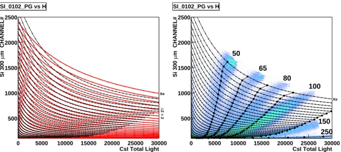
3.1 ∆E-E matrix . . . 33
3.2 Identification in CsI(I). . . 35
3.3 Identification in CsI(II). . . 35
3.4 Identification distributions in INDRA. . . 36
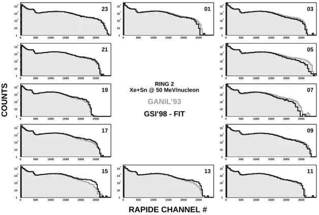
3.5 Total energy spectra (GANIL and GSI). . . 37
3.6 Fit 3rd-4th campaigns. . . 38
3.7 First check of Pˆarlog calibration. . . 39
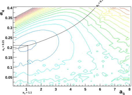
3.8 a3 and a4 as functions of Z. . . 39
3.9 Final check of Pˆarlog calibration. . . 40
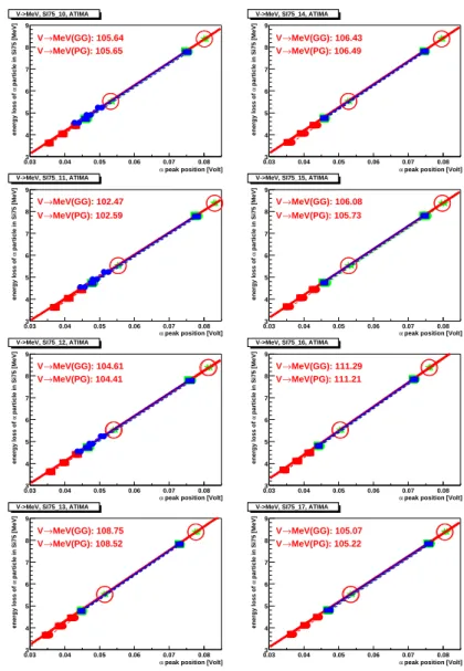
3.10 Alpha sources. . . 41
3.11 Thicknesses of Si75. . . 42
4.1 Correlations between global variables. . . 46
4.2 Possible correlations. . . 47
4.3 BQMD predictions for C+Au at 95 AMeV. . . 48
4.5 BQMD predictions for Xe+Sn at 50 AMeV. . . 49
4.6 Conditional impact parameter distributions for C+Au at 95 AMeV. . . 50
4.7 Rings 6 and 7. . . 51
4.8 Conditional impact parameter distributions, br(X) < 0.1, C+Au at 95 AMeV. . . 52
4.9 Conditional impact parameter distributions, br(X) < 0.1, C+Au at 600 AMeV. . 53
4.10 Conditional impact parameter distributions, br(X) < 0.1, Xe+Sn at 50 AMeV. . 54
4.11 Correlation between NCeven and NCodd. . . 55
4.12 Mean impact parameter. . . 56
4.13 Reduced impact parameter as a function of Nc. . . 57
5.1 Identification of protons in SiLi-CsI. . . 59
5.2 Identification of protons in CsI. . . 60
5.3 Comparison of proton spectra in SiLi-CsI and CsI. . . 61
5.4 Comparison of proton spectra in etalon and CsI. . . 62
5.5 Fit of proton spectra for all the rings. . . 63
5.6 Fit of proton spectra for rings 2 to 5 and 14 to 17. . . 64
5.7 Fit of proton spectra for rings 12 to 17 and 2 to 7. . . 65
5.8 Temperature and velocity of the proton target source. . . 66
5.9 Temperature and velocity of the proton early source. . . 67
5.10 Li`ege and Dresner, b/b0=0.4-0.6. . . 68
5.11 Li`ege and Dresner: b/b0=0.0-0.2. . . 69
5.12 Li`ege and SMM: b/b0=0.0-0.2. . . 70
5.13 Li`ege and Dresner or SMM, b/b0=0.0-0.2 and b/b0=0.6-0.8, rings 10 and 13. . . 71
5.14 Dubna, inclusive, all rings. . . 72
5.15 Isabel, inclusive, all rings. . . 73
5.16 INDRA and EOS proton spectra, inclusive, 4π. . . 74
5.17 Proton proportions in 4π. . . 75
5.18 Proton proportions in INDRA conditions. . . 76
5.19 Proton proportions as functions of θlab. . . 76
5.20 Proton proportions in ALADIN conditions. . . 77
6.1 Charge distributions. . . 79
6.2 IMF multiplicities as functions of Nc. . . 80
6.3 Fits of Li energy spectra (target source). . . 81
6.4 Fits of Li energy spectra. . . 82
6.5 Fits of Be energy spectra. . . 83
6.6 Fits of B energy spectra. . . 84
6.7 Fits of C energy spectra. . . 85
6.8 Fits of N energy spectra. . . 86
6.9 Fits of O energy spectra. . . 87
6.10 Target slope temperatures. . . 88
6.11 Zbound, impact parameter and temperature. . . 89
6.12 Target velocity. . . 90
6.13 Temperature and velocity at low Zbound. . . 91
6.14 Comparison with SMM, b/b0=0.0-0.2. . . 92
6.16 Fits of Li energy spectra for peripheral collisions. . . 94
7.1 Pion cycle in the IQMD model. . . 98
7.2 Delta decay. . . 99
7.3 Matrices Si-CsI with π and fast proton lines. . . 99
7.4 Angular mean multiplicity of pions per steradian for 600 and 1000 AMeV. . . 100
7.5 Multiplicities of pions and fast protons. . . 101
7.6 Multiplicity pion-IMF. . . 102
7.7 Correlation functions pion-IMF and fast proton-IMF. . . 103
7.8 Correlation functions of pion-IMF and fast proton-IMF versus impact parameter. 104 7.9 Rapidity spectra of Li for C+Au at 1000 AMeV. . . 105
7.10 Comparison cascade-experiment for C+Au at 1000 AMeV. . . 106
A.1 Thermodynamical ensembles. . . 113
A.2 Phase diagram (pressure vs density). . . 115
B.1 Cascade process. . . 121
D.1 Li`ege and Dresner: b/b0=0.0-0.2 . . . 136
D.2 Li`ege and Dresner: b/b0=0.2-0.4 . . . 137
D.3 Li`ege and Dresner: b/b0=0.4-0.6 . . . 138
D.4 Li`ege and Dresner: b/b0=0.6-0.8 . . . 139
D.5 Li`ege and Dresner: b/b0=0.8-1.0 . . . 140
D.6 Li`ege and SMM: b/b0=0.0-0.2 . . . 141
D.7 Li`ege and SMM: b/b0=0.2-0.4 . . . 142
D.8 Li`ege and SMM: b/b0=0.4-0.6 . . . 143
D.9 Li`ege and SMM: b/b0=0.6-0.8 . . . 144
Multifragmentation is the emission of several intermediate mass fragments (3 ≤ Z ≤ 30) from a hot nucleus, a phenomenon observed in nuclear reactions, using light and heavy projectiles over a wide range of incident energies. The goal of these studies is to learn more about the tendency of fermionic nuclear matter to appear in clusters and, perhaps eventually, about the topology of the nuclear phase diagram (see Fig. 1), in particular the evasive liquid-to-gas transition. Ad-ditionnally, the explosive features of some of the reactions allow us to study the compressibility of nuclear matter. In fact, the multifragmentation process is believed to appear in the instable region, also called spinodal region, of the nuclear phase diagram where liquid and gas phases coexist. Such information can be important for astrophysical applications as, for instance, during the neutron star formation and the explosion of a supernova of type II. During these processes, the prevailing thermodynamic conditions are expected to be similar to those obtained in the multifragmentation of finite nuclei [Vio98, Bay71, Bet90].
gas nucleusstable metastable regions ρ/ρ0 Temperature (MeV) 0 5 10 15 20 0.00 0.25 0.50 0.75 1.00 1.25 critical point liquid FRAGMENTATION MULTI− spinodal region
Figure 1: Phase diagram of nuclear matter. The temper-ature is plotted as a func-tion of the relative density, ρ0 is the stable nucleus
den-sity. During the collision, the highly excited compound nu-cleus is believed to follow the trajectory indicated by the dashed arrow, from the liquid phase to the spinodal region, where the multifragmentation occurs. This region is a mix-ture of liquid and gas phases and is unstable.
In 1995, the study of the liquid-gas phase transition led to the publication of the first caloric curve, the relation between temperature T and energy E, of nuclear matter by the ALADIN group [Poc95] shown in the left panel of Fig. 2. This caloric curve, obtained from data for the system Au+Au at the incident energy of 600 AMeV, presents a plateau-like behaviour from liquid to gas phases in agreement with the thermodynamical view of multifragmentation. This plateau may be interpreted as a sign of a liquid-gas phase transition.
0 2 4 6 8 10 12 14 16 0 5 10 15 20 25 30 <E0>/<A0>(MeV) T HeLi (MeV) LIQUID VAPOR ALADIN ISIS
}
EOS Au+C at 1 GeV 3 Au+Au at 600 AMeV He+Ag, Au at 4.8 GeVFigure 2: Left panel: Caloric curve for the system Au+Au at the incident energy of 600 AMeV in 1995 [Poc95]. The full line corresponds to the liquid curve and the dashed line to the vapor one. Right panel: Caloric curves in 2001. ALADIN (squares), EOS (dashed lines) and ISIS (dashed-dotted line) data are compared [Ode99, Kwi98, Hau98].
In recent years, several caloric curves for various reaction systems and beam energies were published which show discrepancies between them as exposed in the right panel of Fig. 2 [Ode99, Kwi98, Hau98]. One, if not the main difficulty when comparing caloric curves obtained from different reactions at different incident energies is the determination of the excitation en-ergy. It is obtained by summing up kinetic energies of all particles after equilibration has been achieved. Since a non-negligible amount of light particles is emitted prior to equilibration, the number of these preequilibrium particles and also their energies have to be known. This requires a detailed knowledge of their energy spectra.
Some theoretical models also highlight the importance of the kinetic energies. The statistical multifragmentation model (SMM) points out the contradiction between kinetic and microscopic temperatures [Ode99] (see chapter A.1). The negative heat capacity, considered as a signal of a phase transition, is determined partly from particle kinetic energies [Dag00]. The classical molecular dynamics model (CMD) predicts from fragment kinetic energies that the expansion of the source is a non-equilibrium phenomenon [Cam02].
Fig. 2 also shows that the study of liquid-gas phase transition may imply very different re-actions from light hadron to heavy ion projectiles. In this work we focus on spectator rere-actions in asymmetric systems. Historically, multifragmentation was observed in asymmetric systems [Mey80, Jak82]. Nowadays, the interest comes from the supposed equilibrated source created in this kind of reactions from the largest nucleus, the target in normal kinematics or the projec-tile in inverse kinematics. Asymmetric collisions in normal kinematics were studied by the ISIS and FASA collaborations, also with 12C projectiles in the FASA case [Kwi98, Avd98]. ALADIN
and EOS performed experiments in inverse kinematics, in particular 197Au+12C [Sch96, Hau98].
The latter type of experiments permits the detection of the heavy fragments without threshold, a certain advantage for the study of multifragmentation. However, the hydrogen isotopes are difficult to detect in the ALADIN spectrometer because of their wide distribution in rapidity and their charge-to-mass ratio which is twice that of the fragments. In EOS, a Time Projection Chamber at the target was used for the study of these light particles. In general, the kinetic energies in the source frame are more difficult to determine in inverse kinematics because of the need of a transformation into the moving system.
Because of these limitations of inverse kinematics and the interest in kinetic energies, it was decided to use the INDRA1 4π multidetector (see Fig. 3) to study various systems and incident energy ranges, amoung them 12C+197Au reactions at relativistic beam energies. This detector,
designed for installation at GANIL2, was relocated to GSI3 from 1998 to 1999.
Figure 3: INDRA: exploded view of the detector assembly consisting of 96 ionization chambers, 192 silicon detectors and 336 crystals of cesium iodide organised in 17 rings centered on the beam axis.
Its large angular coverage, 90% of 4π in solid angle, and its very good resolution for light particles make INDRA a good device to study the reaction stages. Of course, this detector also has some disadvantages including thesholds which forbid the detection of the heaviest fragments and upper limits in kinetic energy given by the detector lengths for the light particles.
1
Identification de Noyaux et D´etection avec R´esolution Accrue
2
Grand Acc´el´erateur d’Ions Lourds (Caen, France)
3
The choice of the12C+197Au system [Aug96] at the incident energies from 95 AMeV to 1800
AMeV was determined by the weight of the projectile, heavy enough to produce a maximum number of fragments in central collisions and light enough to avoid δ-electron problems. The use of INDRA with relativistic beams provided an experimental challenge. The beam halo, although negligible in relative intensity, generated considerable amounts of light particles with low multi-plicities at the highest incident energies.
The present thesis is an overview of the new results obtained in the 12C+197Au experiments
of the INDRA@GSI campaign. This campaign was the occasion of the study of several systems over a wide range of energies: Au+Au from 40 to 150 AMeV, Xe+Sn from 20 to 200 AMeV, and C+Au,Sn from 95 to 1800 AMeV. This work gives as an introduction into multifragmentation studies a general presentation of the equation of state applied to nuclear matter, the nuclear temperature and the relativistic heavy ion collisions. The INDRA@GSI experiment is presented in its particularities as are the data reduction methods for particle identification and calibration. The event centrality selection is described with a comparison of different global variables used for the determination of the impact parameter. The main physics topic studied in this work is the eventual determination of the reaction stages, i.e. of the early and target sources, by analysing proton and fragment kinetic energy spectra. The proton spectra are compared to combinations of theoretical models including early and multifragmentation emissions. The characteristics of the fragment target source are compared to previous ALADIN results and to a combination of models supporting the concept of the equilibrated source. The pions, identified for the first time in INDRA, and the fast protons are exploited to study possible correlations between them and intermediate mass fragments. The status of these results is given as a summary and accompanied by a description of future prospects on 12C+197Au reactions and multifragmentation study.
Nuclear Matter
and Relativistic
Heavy Ion Collisions
1.1
Properties of nuclear matter
Nuclear matter is very different from ordinary matter in many aspects. Its density is considerably higher than the one of the bulk matter, its interaction is governed by the strong and weak forces in addition to the electromagnetic forces. Nevertheless, this matter can sometimes be described with macroscopic variables like pressure or temperature in the frame of specific limitations. The evolution of the system consequently to the changes of the macroscopic variables is described by a relation between these variables: the equation of state.
Phase diagram
By analogy to four states of the ordinary matter (gas, liquid, solid, plasma), it is possible to define also such four states to describe the features of the nuclear matter, as sketched by the Fig. 1.1.
The liquid phase, for the low temperatures and densities, corresponds to the nuclear matter in its ground state.
The condensed phase is supposed to be cold matter at high density where nucleons are organised like into a crystal. The protons and neutrons alternate in the net, with neighbouring spins that are oriented in opposite directions.
The gaseous phase appears at fairly high temperatures and low densities at which the nuclei evaporate into a hadron gas. This phase is explored by the high energy physics experiments at CERN, GSI, Fermilab, RHIC, etc...
The plasma phase is predicted for densities of five to ten times the normal density of nuclear matter and for temperatures above around 150 MeV. One should observe then the dissociation of hadrons into their elementary constituents and the appearance of a deconfined mixture of quarks and gluons.
Today most of this diagram still remains unexplored. Only very recent experiments may have permitted to reach the quark-gluon plasma or the condensed phase.
16 Heavy Ion Collisions ✁✁✁✁✁✁✁✁ ✁✁✁✁✁✁✁✁ ✁✁✁✁✁✁✁✁ ✁✁✁✁✁✁✁✁ ✁✁✁✁✁✁✁✁ ✁✁✁✁✁✁✁✁ ✁✁✁✁✁✁✁✁ ✁✁✁✁✁✁✁✁ ✁✁✁✁✁✁✁✁ ✁✁✁✁✁✁✁✁ ✂✁✂✁✂✁✂✁✂✁✂✁✂✁✂ ✂✁✂✁✂✁✂✁✂✁✂✁✂✁✂ ✂✁✂✁✂✁✂✁✂✁✂✁✂✁✂ ✂✁✂✁✂✁✂✁✂✁✂✁✂✁✂ ✂✁✂✁✂✁✂✁✂✁✂✁✂✁✂ ✂✁✂✁✂✁✂✁✂✁✂✁✂✁✂ ✂✁✂✁✂✁✂✁✂✁✂✁✂✁✂ ✂✁✂✁✂✁✂✁✂✁✂✁✂✁✂ ✂✁✂✁✂✁✂✁✂✁✂✁✂✁✂ ✂✁✂✁✂✁✂✁✂✁✂✁✂✁✂ ✄✁✄✁✄✁✄✁✄ ✄✁✄✁✄✁✄✁✄ ✄✁✄✁✄✁✄✁✄ ✄✁✄✁✄✁✄✁✄ ✄✁✄✁✄✁✄✁✄ ✄✁✄✁✄✁✄✁✄ ✄✁✄✁✄✁✄✁✄ ☎✁☎✁☎✁☎✁☎ ☎✁☎✁☎✁☎✁☎ ☎✁☎✁☎✁☎✁☎ ☎✁☎✁☎✁☎✁☎ ☎✁☎✁☎✁☎✁☎ ☎✁☎✁☎✁☎✁☎ ☎✁☎✁☎✁☎✁☎ hadron gas Temperature (MeV) 200 150 100 50 0 ρ/ρ0 quark gluon plasma 0 1 2 3 4 5 6 7 8
liquid condensed phase
gas−plasma coexistence
Figure 1.1: Phase diagram of nuclear matter. The temperature is plotted as a function of the relative density, ρ0is the stable nucleus density. The four states of nuclear matter are represented : liquid, hadron
gas, condensed matter, and quark-gluon plasma.
The equation of state of nuclear matter
Generally, the equation of state of a system is a relation between three thermodynamical vari-ables. Expressed in the most usual form, the nuclear equation of state relates the internal energy E to the density ρ and the temperature T, distinguishing a thermal component and a compression component:
E(ρ, T ) = EC(ρ, T = 0) + ET H(ρ, T ) + E0 (1.1)
with EC(ρ, T = 0): compression energy at T=0, ET H: thermal energy, and E0: binding
en-ergy of the infinite nuclear matter in its ground state.
Fig. 1.2 displays an example of the corresponding shape of the equation of state at temper-ature zero. The top dashed line corresponds to the energy of an excited system, divided in a thermal component ET H and a compression component EC. The notion of saturation means
that, for a sufficiently heavy nucleus, increasing its number of constituents does not modify the density of nucleons in its central part. Reaching a limit value, this density, so-called saturation density ρ0, becomes independent of the nuclear size. This property is fundamental since one
can then assimilate the core of heavy nuclei to infinite nuclear matter. For a system symmetric in numbers of protons and neutrons, the saturation density was theoretically estimated to be ρ0 = 0.17 ± 0.02 nucleon.fm−3. The universality of this value has been confirmed by
exper-iments of nuclear radius measurements. They demonstrated for almost all ground state nuclei the validity of a nuclear radius formula R = r0A1/3 (r0 = 1.2f m) indicating that each nucleon
0 −15 20 40 60 1 2 3 ρ/ρ0 E (AMeV) int E E TH C Saturation Point
Figure 1.2: Predicted equation of state for nuclear matter. The internal energy per nucleon is sketched as a function of the density ρ normalised to the satura-tion density ρ0. The total energy at
tem-perature zero (top dashed line) is com-posed of the thermal component ET H
and the compression component EC.
Different theoretical descriptions have been developped on the basis of the nuclear matter such as the liquid drop model [Eva55]. These approaches authorise, on the basis of the Bethe-Weizs¨acker formulae, the extension of the properties of the infinite nuclear matter to the finite nuclei. Their principle is to introduce parametrised correction terms that take into account the specificity of nuclei due to the effects of surface, Coulombian repulsion, and isospin asymmetry. For a symmetric system of infinite nuclear matter, the term of volume effects gives the binding energy per nucleon E0 estimated to E0=-16 AMeV.
An important parameter of nuclear matter is the compressibility which is determined by the curvature of the internal energy per nucleon as a function of the density. In the vicinity of the saturation point, this function has a minimum and one parametrises the compression energy by a parabolic function like:
Ec(ρ) =
K∞ 18
(ρ − ρ0)2
ρ20 (1.2)
whose quadrature coefficient is fixed by the compressibility module K∞: K∞= 9ρ20 " d2Ec dρ2 # ρ=ρ0 (1.3) The experimental determination of K∞ can be done from giant monopol resonances, or through studies related to astrophysics [Gle88] and to the collective phenomena in heavy ion collisions. The results as obtained until now estimate K∞ to be between 200 and 400 MeV. If K∞ is low (≃ 200 MeV), the equation of state is called soft because one has to give relatively little compression energy to reach high densities. If K∞ is high (≃ 400 MeV), one speaks about a hard equation of state because, one must give a comparatively higher compression energy to reach the same densities.
18 Heavy Ion Collisions
From recent results of the FOPI collaboration [And99, And02], experimental data in compar-ison to IQMD simulations, for Au+Au at 400 and 600 AMeV, seem to be closer to a soft equation of state. A similar report emerges from studies of kaons and pions production in Au+Au and C+C collisions between 600 and 1500 AMeV with the KAOS detector [Stu01, Fuc01].
The difficulties of theoretical approaches
The equation of state permits the macroscopic description of a system through thermodynamical variables. These variables explicitly depend on microscopic properties. So any equation of state is based on the knowledge of the elementary interactions between the constituents.
The nucleon-nucleon interaction potential is known as having a dominant term that is re-pulsive at short range (≤ 0.5 fm) and attractive at longer range (≥ 0.8 fm) [Eva55]. In order to roughly characterise the equation of state of nuclear matter, one can compare the potential to the one of a molecule. This formal correspondence suggests that the equation of state of an infinite system of nucleons is comparable to the one of a Van der Waals gas. It allows to predict the shape of the isotherms and the existence of a liquid-gas phase transition.
Using a more rigorous approach, in particular the fermionic nature of nucleons brings serious problems. In contrary to the simple real fluids, it becomes more difficult to link the nucleon-nucleon interaction to the equation of state. Consequently, the actual models describe only approximatively the saturation point, a basic property of the nuclear matter, from the nucleon-nucleon interaction. Theoretically, the saturation mechanism is defined in a simple way as being the balance between the attractive part of the nuclear interaction potential and the repulsion between nucleons, due to their fermionic nature, and the repulsive part of the potential. But in their attempt to reproduce the saturation point, the calculations technically fail because of n-body forces (from three-body forces to in-medium effects). Concerning this latter point, it means that it is necessary to take into account the contribution of all the other nucleons in the elementary processes of scattering. The Br¨uckner theory is used in this aim in calculating an effective interaction from the free nucleon-nucleon interaction [Eva55]. However, this theory does not describe the saturation point. Another method is to build classes of phenomenologic forces as the Skyrme forces [Vau72]. This approach allows to describe the saturation but this description is obtained by tuning a certain number of free parameters which do not originate from the nucleon-nucleon interaction.
Predictions at finite temperatures
Although the formulation of an equation of state at zero temperature still remains a challenge from the theoretical point of view, it is interesting to attempt an estimate of its shape for finite temperatures. By extending different calculations realised to non-zero temperature, it has been demonstrated that the purely thermal effect on the structure of the nucleon-nucleon interaction is relatively modest [Fri81]. This is the reason why on can use these forces at finite temperature, once parametrized at zero temperature. Such studies [Sau76] predict the behaviour displayed in Fig. 1.3 in the pressure-density plane. We can observe a coexistence region of liquid-gas phases (full line cutting isotherms), defined for temperatures lower than a critical temperature (TC =
is characterised by a mecanically unstable regime for which the fluctuations of density are am-plified, whereas they are attenuated outside these special conditions of ρ and T. This spinodal region corresponds also to a negative compressibility K = −V1 dPdV causing this instability.
Nu-clei reaching this region blow up into several fragments. This phenomenon is supposed to be multifragmentation [Gua96, Gua97]. As this occurrence is believed to take place in a region of coexistence of the liquid and gas phases, multifragmentation is a way to study the transition between these two phases.
✁✁✁✁✁✁✁✁✁ ✁✁✁✁✁✁✁✁✁ ✁✁✁✁✁✁✁✁✁ ✁✁✁✁✁✁✁✁✁ ✁✁✁✁✁✁✁✁✁ ✁✁✁✁✁✁✁✁✁ ✁✁✁✁✁✁✁✁✁ ✁✁✁✁✁✁✁✁✁ ✁✁✁✁✁✁✁✁✁ ✁✁✁✁✁✁✁✁✁ ✁✁✁✁✁✁✁✁✁ ✁✁✁✁✁✁✁✁✁ ✁✁✁✁✁✁✁✁✁ ✁✁✁✁✁✁✁✁✁ ✁✁✁✁✁✁✁✁✁ ✁✁✁✁✁✁✁✁✁ ✁✁✁✁✁✁✁✁✁ ✂✁✂✁✂✁✂✁✂✁✂✁✂✁✂✁✂✁✂ ✂✁✂✁✂✁✂✁✂✁✂✁✂✁✂✁✂✁✂ ✂✁✂✁✂✁✂✁✂✁✂✁✂✁✂✁✂✁✂ ✂✁✂✁✂✁✂✁✂✁✂✁✂✁✂✁✂✁✂ ✂✁✂✁✂✁✂✁✂✁✂✁✂✁✂✁✂✁✂ ✂✁✂✁✂✁✂✁✂✁✂✁✂✁✂✁✂✁✂ ✂✁✂✁✂✁✂✁✂✁✂✁✂✁✂✁✂✁✂ ✂✁✂✁✂✁✂✁✂✁✂✁✂✁✂✁✂✁✂ ✂✁✂✁✂✁✂✁✂✁✂✁✂✁✂✁✂✁✂ ✂✁✂✁✂✁✂✁✂✁✂✁✂✁✂✁✂✁✂ ✂✁✂✁✂✁✂✁✂✁✂✁✂✁✂✁✂✁✂ ✂✁✂✁✂✁✂✁✂✁✂✁✂✁✂✁✂✁✂ ✂✁✂✁✂✁✂✁✂✁✂✁✂✁✂✁✂✁✂ ✂✁✂✁✂✁✂✁✂✁✂✁✂✁✂✁✂✁✂ ✂✁✂✁✂✁✂✁✂✁✂✁✂✁✂✁✂✁✂ ✂✁✂✁✂✁✂✁✂✁✂✁✂✁✂✁✂✁✂ ✂✁✂✁✂✁✂✁✂✁✂✁✂✁✂✁✂✁✂ 0 1 0.5 −0.5 0.05 0.1 0.15 1.5 T=20 12 16 8 4 density (fm )−3 pressure (MeV.fm ) −3 Tc=17.9
Figure 1.3: Predicted equation of state for nuclear matter for different temper-atures indicated in MeV (adapted from [Sau76]). The pressure is sketched as a function of the density. The full line cut-ting the isotherms delimits the coexis-tence region of liquid-gas phases. The spinodal region is represented by the area with circles.
Nuclear temperature
The concept of temperature is well defined in classical statistical mechanics. We attempt to apply this definition to nuclear systems although some shortcomings are present: the short time range of the reaction, the finite size of the system, the complex dynamics, and the various interactions which occur in a collision.
One of the fundamental quantities used in classical statistical mechanics is the number of states Γ(E, N ) of a given system with a particle number N which lies in the vicinity ∆E of the energy E. This function is directly proportional to the density of states ρ(E, N ) at energy E, such that:
Γ(E, N ) = ρ(E, N ).∆E (1.4)
It is also convenient to introduce the entropy of the system S(E, N ):
20 Heavy Ion Collisions
With these quantities, the definition of the temperature provided by statistical mechanics is: 1 T = ∂S ∂E = ∂ln(ρ(E, N )) ∂E (1.6)
where ∆E is considered independent of E. This definition is applicable to any isolated sys-tem, like a nuclear system if one regards the very short range of the nuclear force.
While the formal definition of temperature is simple, the relevance of the concept and its measurability depend on further requirements which, in more realistic nuclear cases, one may only approximately meet. The excitation of an isolated system can be characterised by an energy but, in order to determine its temperature, two additional major features must be known: the degree of equilibration and the specific density of states. The most critical of these requirements is that the ensemble must be in full statistical equilibrium. This means that each of the states included in ρ(E, N ) is populated with equal probability. For highly excited nuclear systems, the requirement of full equilibrium may be difficult to achieve in practice. With the increase of the excitation energy, a reduction of the lifetime of the system is observed and a homogeneous population of the states becomes less probable.
It is difficult to know, a priori, the degree of equilibrium of a nuclear system because the dynamics are complex and only partly known. Nevertheless, previous works on relativistic heavy-ion collisheavy-ions present results indicating an independence of fragment emissheavy-ion to incident energy that may be interpreted as a signal of an equilibration [Sch96, Ode99]. To continue the explo-ration of equilibrium, it is instructive to assume that the population of states is sufficiently complete to allow the utilisation of the concept of temperature for nuclear systems.
1.2
Relativistic heavy ion collisions.
projectile projectilespectator
fireball
target target
spectator
Figure 1.4:After collision, there exists three sources of light particles and fragments: the projectile and target spectators and the participant region, so-called ‘fireball’.
The heavy ion collisions at relativistic energies (100 AMeV ≤ Elab ≤ 2 AGeV) are the unique
tool to study in the laboratory nucleonic systems under extreme conditions of temperature and pressure. It is hoped to access to the properties of nuclear matter by exploring wide regions of
its phase diagram and to reach thromodynamical conditions that are similar to the inner part of supernovae, of the neutron stars and in the early universe. At relativistic energies, the collision can be described within the geometrical participant-spectator picture. In this scheme, that is shown in Fig. 1.4, a geometrical overlap region between the target and the projectile is associated to each impact parameter. When this region is sufficiently large, a so-called ‘fireball’ is created, which is the seat of high densities and temperatures. The fireball contains the ‘participant’ nucleons wich are supposed to be free during its explosion. The residues of the target and the projectile, outside the overlapping region, are excited by the collision. They constitute the ‘spectator’ matter that deexcites by evaporation or multifragmentation.
preequilibrium emission
OF OF
liquid drops=
At freeze−out : thermal and chemical equilibrium
fragments (Z>2)
STARTING POINT STATISTICAL MODELS STARTING POINT
DYNAMICAL MODELS
Figure 1.5:Possible multifragmentation scenario.
The mechanisms taking place in a heavy-ion reaction have dynamical and statistical aspects. A deep knowledge of these mechanisms is needed in order to extract the equation of state. The heavy ion collisions at relativistic energies may lead to different processes, from the formation of a compound system that deexcites by evaporation to the total disintegration of the system into a hadron gas. The intermediate regime is characterised by the breakup of the nuclear system into fragments (Z ≥ 2) of various masses and several nucleons (see Fig. 1.5). This is accom-panied, at sufficient incident energy, by the production of additional hadrons such as pions, kaons, etc... The usually believed scenario of collisions can be schematically decomposed into three stages. First, the penetration of the two nuclei causes a phase of heating and compression during which the temperature reaches some tens of MeV and the density two to five times the normal density. When the maximal density is reached, at about 15 fm/c (5.10−23 s) after the
contact of the nuclei, an expansion stage begins until the reaction products do not interact any more with each other, the so-called ‘freeze-out’ stage. At this point, the system dissociates into
22 Heavy Ion Collisions
aggregates and various components. A first emission of light particles (n, p, d, t, 3He, 4He)
and elementary particles like pions is observed before and during the expansion stage. At the breakup of the composite system, there is emission of light particles, intermediate mass frag-ments (3 ≤ Z ≤ 30), and heavy fragfrag-ments (Z ≥ 30). Finally, subsequently ‘secondary’ light particles are produced from the de-excitation of the emitted fragments. the total length of the collision varies with the system and the incident energy but it is roughly around 150 to 200 fm/c. The formation mechanism of the fragments, whether they are the remnants of an incom-plete destruction or the products of a condensation out of the disordered matter, is still the topic of very active research [Bon95b, Mor93, Fel99]. In order to investigate this question, re-cent experiments with the ISiS detector at Brookhaven studied reactions of energetic hadrons including pions and antiprotons with gold targets in a momentum range from 5 GeV/c to 14.6 GeV/c [Lef99b, Bea99, Bea00]. The aim of these experiments was to determine the role of the excitation energy in the fragment production. It is based on the expectation, tested with intra-nuclear cascade calculations (see appendix B), that light energetic projectiles will generate a statistical (thermal) disorder without exciting collective modes such as compression, rotation, or shape deformations. These are known to break nuclei very efficiently and would mask the nuclear response to the thermal excitation [Col97]. The ISiS experiments show that the antipro-ton projectiles at high momentum may generate a very high excitation energy. However, the corresponding fragment multiplicities are significantly smaller for the less energetic antiproton beam for the same range of excitation energy. It is therefore an open question whether the ex-citation energy by itself is the only parameter that governs the decay properties and fragment production. While this may be partly connected to the difficulties inherent with experimentally determining the excitation energy [Sch96], it is nevertheless obvious that the solution of this problem will help to better understand how fragments are formed [Ode00].
The limits of generating excitation energy can be overcome with composite projectiles. Sys-tematic sets of data with projectiles of various mass and energy have been collected by different collaborations as ALADIN, EOS, or FASA [Sch96, Hau00, Avd98]. The ALADIN results ex-hibit a contimuing rise of the cross-section for high excitations with increasing mass of the target for the fragmentation of gold projectiles while the isotopic temperatures THeLi remain
independent. These isotopic temperatures are determined from the double ratio of the yields of two pairs of nuclides with the same differences in neutron and proton numbers, 3He/4He and
6Li/7Li, according to the method suggested by Albergo and coworkers [Alb85]. However these
temperatures present a dependence on the variable Zbound, representing the sum of the atomic
numbers Zi of all projectile fragments with Zi ≥ 2, which is inversely correlated with the
ex-citation energy. The isotopic temperatures tend to their highest values (THeLi ∼ 11 MeV) at
low Zbound, i.e. at the highest excitation energies reached in these reactions. Large systems at
even higher excitations can be produced in central collisions. In this case, the idea of excitation as a simple heating process has to be abandoned. Collective modes, compression as well as the directed outward motion of particles and clusters from primary collisions generate an explosive pattern, quantified as collective radial flow [Rei97]. The production of large clusters is rare and inversely correlated with the observed amount of flow. Some features of these energetic reactions have been reproduced with molecular dynamics calculations [Chi00] but to fully understand the clusterization mechanism in the dynamical environment still remains an interesting problem of future research.
INDRA@GSI Experiment
In 1998 and 1999, a series of experiments was conducted at GSI with the INDRA multidetector. Several projectile-target systems over a wide range of energies were studied, Au+Au from 40 to 150 AMeV, Xe+Sn from 20 to 200 AMeV, and C+Au and C+Sn from 95 to 1800 AMeV. Enriched targets of112,124Sn were used in order to study isotopic effects.
The 4π-multidetector INDRA was developed at GANIL by a collaboration of French labora-tories : GANIL, IPNO1, DAPNIA2, and LPC3. The INDRA detector is also used by the IPNL 4, Italian, Canadian, and Romanian groups. Three experimental campains have been performed
at GANIL in 1993, 1994, and 1997 at intermediate energies (energies limited at 29 AMeV for Au).
These three campaigns of INDRA at GANIL have been devoted to the study of the pro-duction and decay modes of excited nuclei produced with intermediate-energy heavy-ion beams. The continuation of these measurements and their extension to higher beam energies, accessi-ble with the heavy-ion synchrotron SIS, hase been one of the motivations for the INDRA@GSI campaign.
The present chapter describes briefly the accelerator devices of GSI and the INDRA detector and focus on technical particularities of the experiment, especially the relativistic energy part.
2.1
GSI accelerator facility
GSI operates a heavy ion accelerator facility consisting of the linear accelerator UNILAC (energy of 2 - 20 AMeV), the synchrotron SIS5 18 (1 - 2 GeV/u), and the experimental storage ring ESR6 (E < 1 AGeV) (Fig. 2.1). Ions from a Penning source are injected by the North and South injectors and then pass through the adjoining Wider¨oe structure. Alternatively, they originate in the high-charge injector before being into the Alvarez structure of the UNILAC at about 5% of the speed of light. In the UNILAC, the ion beam reaches 16% of the speed of light. Part of the
1
Institut de Physique Nucl´eaire d’Orsay, Paris (France)
2
D´epartement d’Astrophysique, de physique des Particules, de physique Nucl´eaire et de l’Instrumentation Associ´ee
3
Laboratoire de Physique des Corpuscules, Caen (France)
4
Institut de Physique Nucl´eaire de Lyon, Lyon (France)
5
SchwerIonenSynchrotron
Figure 2.1: GSI acceleration facility: UNILAC (Linac), SIS (Synchrotron), ESR (Storage Ring)
beam is then diverted to the adjoining experimental hall for experiments, while the remainder is transferred to the heavy ion synchrotron SIS for further acceleration. There, the ions reach up to 90% of the speed of light, before being directed to experiments at the fragment separator FRS, the ESR, or the target hall.
During this experimental campaign, the INDRA detector was installed in the cave B, in the target hall.
2.2
INDRA multidetector
The 4π-multidetector INDRA offers high capabilities for the simultaneous detection of the nu-merous light charged particles and nuclear fragments that are emitted during heavy ion collisions. A total of 640 individual detectors (ionisation chambers, silicon detectors and cesium iodide crys-tals) covers 90% of the 4π solid angle (see Fig. 2.2) [Pou95].
These 640 detectors are organised in 336 modules. Each module consists of two or three detectors according to the angle: 96 ionisation chambers, 192 silicon diodes (Si), 336 thallium activated Cesium Iodide scintillators (CsI). The telescopes are grouped in 17 rings around the beam axis. Each ring consists of 8, 12, 16 or 24 detection modules.
Figure 2.2: INDRA: a detector assembly consisting of 17 rings (‘Couronnes’) of telescopes covering 90% of 4π around the target (‘Cible’) [Pou95].
These rings have the following types of modules: - ring 1 (2o≤ θ
lab ≤ 3o) : 12 telescopes of Si’s and CsI’s with photomultipliers, newly developped
for INDRA@GSI.
- rings 2 to 9 (3o ≤ θlab ≤ 45o) : 12 or 24 telescopes of ionisation chambers, Si’s and CsI’s with
photomultipliers (Fig. 2.3, left panel).
- rings 10 to 17 (45o ≤ θlab≤ 178o) : 8, 16 or 24 modules of ionisation chambers and CsI’s with
photomultipliers.
Figure 2.3: Left-hand side: a typical INDRA module (between 7o and 45o). The detectable particle
(longest arrow) punches trough the ionisation chamber, the silicon detector, and ends up in the CsI(Tl) crystal. Right-hand side:: mechanical assembly of the 8 Si-Si-CsI(Tl) telescopes in rings 10 to 17 of the INDRA detector (θlab> 45◦). The silicon detectors are represented by the disks in front of the CsI crystals
which are facing the target (cible). The dashed line corresponds to the beam (faisceau) axis [Pou95].
The INDRA geometry was optimised for the observation of multiple fragment emission. The most forward ring has to withstand a high rate due to elastic scattering. Rings 2 to 9 have to cover a large energy range and to avoid the double counts, the backward rings complete the angular coverage.
A part of the INDRA@GSI campaign has been dedicated to asymmetric systems like12C+197Au
and 12C+112,124Sn at beam energies ranging from 95 to 1800 AMeV. The 12C+197Au system is
the purpose of the present work. The velocity of the target spectators is small also at relativistic energies, and their emission nearly isotropic in the laboratory frame while light particles from the initial reaction stages are forward peaked. Consequently, the study of spectator fragmenta-tion is better achieved at backward angles where, however, a good isotopic resolufragmenta-tion with low threshold is only provided by the Si-Si-CsI(Tl) calibration telescopes of INDRA (Fig. 2.3, right panel). These eight telescopes are distributed in the angular range from 45◦ to 180◦, one
mod-ule per ring, and consist of two circular silicon detectors of 2cm of diameter, a 80-µm detector followed by a Si(Li) detector with thickness 2000 µm, mounted between the ionisation chamber and the CsI(Tl) crystal of a telescope module.
2.3
The experimental setup: INDRA at GSI
The move of INDRA to GSI presents some setup particularities because of the very narrow entrance of the detector: 12 mm of diameter. As the beam emittance of a synchrotron (GSI) is larger than that of a cyclotron (GANIL), it is essential to control very carefully the beam focalisation all along the beam axis before and during the experiment[Tur98].
✁ ✁ ✁ ✁ ✁ ✁ ✁ ✁ ✁ ✂✁✂ ✂✁✂ ✂✁✂ ✂✁✂ ✂✁✂ ✂✁✂ ✂✁✂ ✂✁✂ ✂✁✂ ✄✁✄ ✄✁✄ ✄✁✄ ✄✁✄ ✄✁✄ ✄✁✄ ✄✁✄ ✄✁✄ ✄✁✄ ☎✁☎ ☎✁☎ ☎✁☎ ☎✁☎ ☎✁☎ ☎✁☎ ☎✁☎ ☎✁☎ ☎✁☎ ✆ ✆ ✆ ✝ ✝ ✝ ✞✁✞ ✞✁✞ ✟✁✟ ✟✁✟ ✠ ✠ ✡ ✡ ☛ ☞ ✌✁✌✁✌ ✍✁✍✁✍✎✁✎ ✎✁✎ ✏✁✏ ✏✁✏ ✑✁✑ ✒✁✒✓✁✓ ✓✁✓ ✔✁✔ ✔✁✔ ✕✁✕✁✕ ✖✁✖✁✖ ✗✁✗ ✗✁✗ ✘✁✘ ✘✁✘ ✙✁✙✁✙✁✙✁✙ ✙✁✙✁✙✁✙✁✙ ✙✁✙✁✙✁✙✁✙ ✙✁✙✁✙✁✙✁✙ ✙✁✙✁✙✁✙✁✙ ✚✁✚✁✚✁✚ ✚✁✚✁✚✁✚ ✚✁✚✁✚✁✚ ✚✁✚✁✚✁✚ ✚✁✚✁✚✁✚ Quadru− poles GSI Quadru− poles GANIL Scintillator and Video
Target and 4Segments Scintillator Halo Detector Target Beam Axis 11.12 m 2.48 m 2.68 m Profiler Profiler ionisation Chamber Plastic Scintillator INDRA ALADIN FOPI Faraday Cup ✛✁✛ ✛✁✛ ✜✁✜ ✜✁✜ ✢✁✢ ✢✁✢ ✣✁✣ ✣✁✣
Figure 2.4: Experimental setup of INDRA@GSI experiment in cave B at GSI.
Along the beam line (from the last GSI quadrupole towards INDRA), as it is drawn in Fig. 2.4, one finds successively a scintillator target with video, the two GANIL quadrupoles, a first profiler in front of a Faraday cup, a halo detector, the INDRA reaction chamber, and a second profiler back. The first ring of INDRA (2o − 3o) is shielded with a removable brass plate, 2cm thickness, in order to avoid hard damages during the focalisation.
The scintillator target with its video is used to control the position of the beam just before the GANIL quadrupoles. These quadrupoles play a major role in the beam focalisation. They
permit the focalisation on the target by focusing first on the front profiler and afterwards and the back profiler. The focalisation on the target is determined knowing the quadrupole current densities corresponding to this two tunings and the distances between the profilers and the tar-get. For the non-relativistic beams of the INDRA@GSI campaign, the Faraday cup may protect INDRA during the first beam settings while the beam intensity is lowered from 107 to 104 par-ticles per spill.
✁✁✁✁✁✁✁✁✁✁✁✁✁✁✁✁✁✁✁✁✁✁ ✁✁✁✁✁✁✁✁✁✁✁✁✁✁✁✁✁✁✁✁✁✁ ✁✁✁✁✁✁✁✁✁✁✁✁✁✁✁✁✁✁✁✁✁✁ ✁✁✁✁✁✁✁✁✁✁✁✁✁✁✁✁✁✁✁✁✁✁ ✁✁✁✁✁✁✁✁✁✁✁✁✁✁✁✁✁✁✁✁✁✁ ✁✁✁✁✁✁✁✁✁✁✁✁✁✁✁✁✁✁✁✁✁✁ ✁✁✁✁✁✁✁✁✁✁✁✁✁✁✁✁✁✁✁✁✁✁ ✁✁✁✁✁✁✁✁✁✁✁✁✁✁✁✁✁✁✁✁✁✁ ✁✁✁✁✁✁✁✁✁✁✁✁✁✁✁✁✁✁✁✁✁✁ ✁✁✁✁✁✁✁✁✁✁✁✁✁✁✁✁✁✁✁✁✁✁ ✁✁✁✁✁✁✁✁✁✁✁✁✁✁✁✁✁✁✁✁✁✁ ✁✁✁✁✁✁✁✁✁✁✁✁✁✁✁✁✁✁✁✁✁✁ ✁✁✁✁✁✁✁✁✁✁✁✁✁✁✁✁✁✁✁✁✁✁ ✁✁✁✁✁✁✁✁✁✁✁✁✁✁✁✁✁✁✁✁✁✁ ✁✁✁✁✁✁✁✁✁✁✁✁✁✁✁✁✁✁✁✁✁✁ ✁✁✁✁✁✁✁✁✁✁✁✁✁✁✁✁✁✁✁✁✁✁ ✁✁✁✁✁✁✁✁✁✁✁✁✁✁✁✁✁✁✁✁✁✁ ✁✁✁✁✁✁✁✁✁✁✁✁✁✁✁✁✁✁✁✁✁✁ ✁✁✁✁✁✁✁✁✁✁✁✁✁✁✁✁✁✁✁✁✁✁ ✁✁✁✁✁✁✁✁✁✁✁✁✁✁✁✁✁✁✁✁✁✁ ✁✁✁✁✁✁✁✁✁✁✁✁✁✁✁✁✁✁✁✁✁✁ ✁✁✁✁✁✁✁✁✁✁✁✁✁✁✁✁✁✁✁✁✁✁ ✂✁✂✁✂✁✂✁✂✁✂✁✂✁✂✁✂✁✂✁✂✁✂✁✂✁✂✁✂✁✂✁✂✁✂✁✂✁✂✁✂✁✂✁✂ ✂✁✂✁✂✁✂✁✂✁✂✁✂✁✂✁✂✁✂✁✂✁✂✁✂✁✂✁✂✁✂✁✂✁✂✁✂✁✂✁✂✁✂✁✂ ✂✁✂✁✂✁✂✁✂✁✂✁✂✁✂✁✂✁✂✁✂✁✂✁✂✁✂✁✂✁✂✁✂✁✂✁✂✁✂✁✂✁✂✁✂ ✂✁✂✁✂✁✂✁✂✁✂✁✂✁✂✁✂✁✂✁✂✁✂✁✂✁✂✁✂✁✂✁✂✁✂✁✂✁✂✁✂✁✂✁✂ ✂✁✂✁✂✁✂✁✂✁✂✁✂✁✂✁✂✁✂✁✂✁✂✁✂✁✂✁✂✁✂✁✂✁✂✁✂✁✂✁✂✁✂✁✂ ✂✁✂✁✂✁✂✁✂✁✂✁✂✁✂✁✂✁✂✁✂✁✂✁✂✁✂✁✂✁✂✁✂✁✂✁✂✁✂✁✂✁✂✁✂ ✂✁✂✁✂✁✂✁✂✁✂✁✂✁✂✁✂✁✂✁✂✁✂✁✂✁✂✁✂✁✂✁✂✁✂✁✂✁✂✁✂✁✂✁✂ ✂✁✂✁✂✁✂✁✂✁✂✁✂✁✂✁✂✁✂✁✂✁✂✁✂✁✂✁✂✁✂✁✂✁✂✁✂✁✂✁✂✁✂✁✂ ✂✁✂✁✂✁✂✁✂✁✂✁✂✁✂✁✂✁✂✁✂✁✂✁✂✁✂✁✂✁✂✁✂✁✂✁✂✁✂✁✂✁✂✁✂ ✂✁✂✁✂✁✂✁✂✁✂✁✂✁✂✁✂✁✂✁✂✁✂✁✂✁✂✁✂✁✂✁✂✁✂✁✂✁✂✁✂✁✂✁✂ ✂✁✂✁✂✁✂✁✂✁✂✁✂✁✂✁✂✁✂✁✂✁✂✁✂✁✂✁✂✁✂✁✂✁✂✁✂✁✂✁✂✁✂✁✂ ✂✁✂✁✂✁✂✁✂✁✂✁✂✁✂✁✂✁✂✁✂✁✂✁✂✁✂✁✂✁✂✁✂✁✂✁✂✁✂✁✂✁✂✁✂ ✂✁✂✁✂✁✂✁✂✁✂✁✂✁✂✁✂✁✂✁✂✁✂✁✂✁✂✁✂✁✂✁✂✁✂✁✂✁✂✁✂✁✂✁✂ ✂✁✂✁✂✁✂✁✂✁✂✁✂✁✂✁✂✁✂✁✂✁✂✁✂✁✂✁✂✁✂✁✂✁✂✁✂✁✂✁✂✁✂✁✂ ✂✁✂✁✂✁✂✁✂✁✂✁✂✁✂✁✂✁✂✁✂✁✂✁✂✁✂✁✂✁✂✁✂✁✂✁✂✁✂✁✂✁✂✁✂ ✂✁✂✁✂✁✂✁✂✁✂✁✂✁✂✁✂✁✂✁✂✁✂✁✂✁✂✁✂✁✂✁✂✁✂✁✂✁✂✁✂✁✂✁✂ ✂✁✂✁✂✁✂✁✂✁✂✁✂✁✂✁✂✁✂✁✂✁✂✁✂✁✂✁✂✁✂✁✂✁✂✁✂✁✂✁✂✁✂✁✂ ✂✁✂✁✂✁✂✁✂✁✂✁✂✁✂✁✂✁✂✁✂✁✂✁✂✁✂✁✂✁✂✁✂✁✂✁✂✁✂✁✂✁✂✁✂ ✂✁✂✁✂✁✂✁✂✁✂✁✂✁✂✁✂✁✂✁✂✁✂✁✂✁✂✁✂✁✂✁✂✁✂✁✂✁✂✁✂✁✂✁✂ ✂✁✂✁✂✁✂✁✂✁✂✁✂✁✂✁✂✁✂✁✂✁✂✁✂✁✂✁✂✁✂✁✂✁✂✁✂✁✂✁✂✁✂✁✂ ✂✁✂✁✂✁✂✁✂✁✂✁✂✁✂✁✂✁✂✁✂✁✂✁✂✁✂✁✂✁✂✁✂✁✂✁✂✁✂✁✂✁✂✁✂ ✂✁✂✁✂✁✂✁✂✁✂✁✂✁✂✁✂✁✂✁✂✁✂✁✂✁✂✁✂✁✂✁✂✁✂✁✂✁✂✁✂✁✂✁✂ Plexiglas Plastic Scintillator Aluminium Plate 11 mm 20 mm PM Halo Plastic Scintillator 4−Segments Photodiode PM PM 20 mm ✄✁✄✁✄✁✄✁✄✁✄✁✄✁✄✁✄✁✄✁✄✁✄✁✄✁✄✁✄✁✄ ✄✁✄✁✄✁✄✁✄✁✄✁✄✁✄✁✄✁✄✁✄✁✄✁✄✁✄✁✄✁✄ ✄✁✄✁✄✁✄✁✄✁✄✁✄✁✄✁✄✁✄✁✄✁✄✁✄✁✄✁✄✁✄ ✄✁✄✁✄✁✄✁✄✁✄✁✄✁✄✁✄✁✄✁✄✁✄✁✄✁✄✁✄✁✄ ✄✁✄✁✄✁✄✁✄✁✄✁✄✁✄✁✄✁✄✁✄✁✄✁✄✁✄✁✄✁✄ ✄✁✄✁✄✁✄✁✄✁✄✁✄✁✄✁✄✁✄✁✄✁✄✁✄✁✄✁✄✁✄ ✄✁✄✁✄✁✄✁✄✁✄✁✄✁✄✁✄✁✄✁✄✁✄✁✄✁✄✁✄✁✄ ✄✁✄✁✄✁✄✁✄✁✄✁✄✁✄✁✄✁✄✁✄✁✄✁✄✁✄✁✄✁✄ ✄✁✄✁✄✁✄✁✄✁✄✁✄✁✄✁✄✁✄✁✄✁✄✁✄✁✄✁✄✁✄ ✄✁✄✁✄✁✄✁✄✁✄✁✄✁✄✁✄✁✄✁✄✁✄✁✄✁✄✁✄✁✄ ✄✁✄✁✄✁✄✁✄✁✄✁✄✁✄✁✄✁✄✁✄✁✄✁✄✁✄✁✄✁✄ ✄✁✄✁✄✁✄✁✄✁✄✁✄✁✄✁✄✁✄✁✄✁✄✁✄✁✄✁✄✁✄ ✄✁✄✁✄✁✄✁✄✁✄✁✄✁✄✁✄✁✄✁✄✁✄✁✄✁✄✁✄✁✄ ✄✁✄✁✄✁✄✁✄✁✄✁✄✁✄✁✄✁✄✁✄✁✄✁✄✁✄✁✄✁✄ ✄✁✄✁✄✁✄✁✄✁✄✁✄✁✄✁✄✁✄✁✄✁✄✁✄✁✄✁✄✁✄ ✄✁✄✁✄✁✄✁✄✁✄✁✄✁✄✁✄✁✄✁✄✁✄✁✄✁✄✁✄✁✄ ☎✁☎✁☎✁☎✁☎✁☎✁☎✁☎✁☎✁☎✁☎✁☎✁☎✁☎✁☎✁☎ ☎✁☎✁☎✁☎✁☎✁☎✁☎✁☎✁☎✁☎✁☎✁☎✁☎✁☎✁☎✁☎ ☎✁☎✁☎✁☎✁☎✁☎✁☎✁☎✁☎✁☎✁☎✁☎✁☎✁☎✁☎✁☎ ☎✁☎✁☎✁☎✁☎✁☎✁☎✁☎✁☎✁☎✁☎✁☎✁☎✁☎✁☎✁☎ ☎✁☎✁☎✁☎✁☎✁☎✁☎✁☎✁☎✁☎✁☎✁☎✁☎✁☎✁☎✁☎ ☎✁☎✁☎✁☎✁☎✁☎✁☎✁☎✁☎✁☎✁☎✁☎✁☎✁☎✁☎✁☎ ☎✁☎✁☎✁☎✁☎✁☎✁☎✁☎✁☎✁☎✁☎✁☎✁☎✁☎✁☎✁☎ ☎✁☎✁☎✁☎✁☎✁☎✁☎✁☎✁☎✁☎✁☎✁☎✁☎✁☎✁☎✁☎ ☎✁☎✁☎✁☎✁☎✁☎✁☎✁☎✁☎✁☎✁☎✁☎✁☎✁☎✁☎✁☎ ☎✁☎✁☎✁☎✁☎✁☎✁☎✁☎✁☎✁☎✁☎✁☎✁☎✁☎✁☎✁☎ ☎✁☎✁☎✁☎✁☎✁☎✁☎✁☎✁☎✁☎✁☎✁☎✁☎✁☎✁☎✁☎ ☎✁☎✁☎✁☎✁☎✁☎✁☎✁☎✁☎✁☎✁☎✁☎✁☎✁☎✁☎✁☎ ☎✁☎✁☎✁☎✁☎✁☎✁☎✁☎✁☎✁☎✁☎✁☎✁☎✁☎✁☎✁☎ ☎✁☎✁☎✁☎✁☎✁☎✁☎✁☎✁☎✁☎✁☎✁☎✁☎✁☎✁☎✁☎ ☎✁☎✁☎✁☎✁☎✁☎✁☎✁☎✁☎✁☎✁☎✁☎✁☎✁☎✁☎✁☎ ☎✁☎✁☎✁☎✁☎✁☎✁☎✁☎✁☎✁☎✁☎✁☎✁☎✁☎✁☎✁☎ ✆✁✆✁✆✁✆✁✆✁✆✁✆✁✆✁✆✁✆✁✆✁✆✁✆✁✆ ✆✁✆✁✆✁✆✁✆✁✆✁✆✁✆✁✆✁✆✁✆✁✆✁✆✁✆ ✆✁✆✁✆✁✆✁✆✁✆✁✆✁✆✁✆✁✆✁✆✁✆✁✆✁✆ ✆✁✆✁✆✁✆✁✆✁✆✁✆✁✆✁✆✁✆✁✆✁✆✁✆✁✆ ✆✁✆✁✆✁✆✁✆✁✆✁✆✁✆✁✆✁✆✁✆✁✆✁✆✁✆ ✆✁✆✁✆✁✆✁✆✁✆✁✆✁✆✁✆✁✆✁✆✁✆✁✆✁✆ ✆✁✆✁✆✁✆✁✆✁✆✁✆✁✆✁✆✁✆✁✆✁✆✁✆✁✆ ✆✁✆✁✆✁✆✁✆✁✆✁✆✁✆✁✆✁✆✁✆✁✆✁✆✁✆ ✆✁✆✁✆✁✆✁✆✁✆✁✆✁✆✁✆✁✆✁✆✁✆✁✆✁✆ ✆✁✆✁✆✁✆✁✆✁✆✁✆✁✆✁✆✁✆✁✆✁✆✁✆✁✆ ✆✁✆✁✆✁✆✁✆✁✆✁✆✁✆✁✆✁✆✁✆✁✆✁✆✁✆ ✆✁✆✁✆✁✆✁✆✁✆✁✆✁✆✁✆✁✆✁✆✁✆✁✆✁✆ ✆✁✆✁✆✁✆✁✆✁✆✁✆✁✆✁✆✁✆✁✆✁✆✁✆✁✆ ✆✁✆✁✆✁✆✁✆✁✆✁✆✁✆✁✆✁✆✁✆✁✆✁✆✁✆ ✆✁✆✁✆✁✆✁✆✁✆✁✆✁✆✁✆✁✆✁✆✁✆✁✆✁✆ ✆✁✆✁✆✁✆✁✆✁✆✁✆✁✆✁✆✁✆✁✆✁✆✁✆✁✆ ✆✁✆✁✆✁✆✁✆✁✆✁✆✁✆✁✆✁✆✁✆✁✆✁✆✁✆ ✆✁✆✁✆✁✆✁✆✁✆✁✆✁✆✁✆✁✆✁✆✁✆✁✆✁✆ ✆✁✆✁✆✁✆✁✆✁✆✁✆✁✆✁✆✁✆✁✆✁✆✁✆✁✆ ✆✁✆✁✆✁✆✁✆✁✆✁✆✁✆✁✆✁✆✁✆✁✆✁✆✁✆ ✆✁✆✁✆✁✆✁✆✁✆✁✆✁✆✁✆✁✆✁✆✁✆✁✆✁✆ ✆✁✆✁✆✁✆✁✆✁✆✁✆✁✆✁✆✁✆✁✆✁✆✁✆✁✆ ✆✁✆✁✆✁✆✁✆✁✆✁✆✁✆✁✆✁✆✁✆✁✆✁✆✁✆ ✆✁✆✁✆✁✆✁✆✁✆✁✆✁✆✁✆✁✆✁✆✁✆✁✆✁✆ ✆✁✆✁✆✁✆✁✆✁✆✁✆✁✆✁✆✁✆✁✆✁✆✁✆✁✆ ✆✁✆✁✆✁✆✁✆✁✆✁✆✁✆✁✆✁✆✁✆✁✆✁✆✁✆ ✆✁✆✁✆✁✆✁✆✁✆✁✆✁✆✁✆✁✆✁✆✁✆✁✆✁✆ ✝✁✝✁✝✁✝✁✝✁✝✁✝✁✝✁✝✁✝✁✝✁✝✁✝ ✝✁✝✁✝✁✝✁✝✁✝✁✝✁✝✁✝✁✝✁✝✁✝✁✝ ✝✁✝✁✝✁✝✁✝✁✝✁✝✁✝✁✝✁✝✁✝✁✝✁✝ ✝✁✝✁✝✁✝✁✝✁✝✁✝✁✝✁✝✁✝✁✝✁✝✁✝ ✝✁✝✁✝✁✝✁✝✁✝✁✝✁✝✁✝✁✝✁✝✁✝✁✝ ✝✁✝✁✝✁✝✁✝✁✝✁✝✁✝✁✝✁✝✁✝✁✝✁✝ ✝✁✝✁✝✁✝✁✝✁✝✁✝✁✝✁✝✁✝✁✝✁✝✁✝ ✝✁✝✁✝✁✝✁✝✁✝✁✝✁✝✁✝✁✝✁✝✁✝✁✝ ✝✁✝✁✝✁✝✁✝✁✝✁✝✁✝✁✝✁✝✁✝✁✝✁✝ ✝✁✝✁✝✁✝✁✝✁✝✁✝✁✝✁✝✁✝✁✝✁✝✁✝ ✝✁✝✁✝✁✝✁✝✁✝✁✝✁✝✁✝✁✝✁✝✁✝✁✝ ✝✁✝✁✝✁✝✁✝✁✝✁✝✁✝✁✝✁✝✁✝✁✝✁✝ ✝✁✝✁✝✁✝✁✝✁✝✁✝✁✝✁✝✁✝✁✝✁✝✁✝ ✝✁✝✁✝✁✝✁✝✁✝✁✝✁✝✁✝✁✝✁✝✁✝✁✝ ✝✁✝✁✝✁✝✁✝✁✝✁✝✁✝✁✝✁✝✁✝✁✝✁✝ ✝✁✝✁✝✁✝✁✝✁✝✁✝✁✝✁✝✁✝✁✝✁✝✁✝ ✝✁✝✁✝✁✝✁✝✁✝✁✝✁✝✁✝✁✝✁✝✁✝✁✝ ✝✁✝✁✝✁✝✁✝✁✝✁✝✁✝✁✝✁✝✁✝✁✝✁✝ ✝✁✝✁✝✁✝✁✝✁✝✁✝✁✝✁✝✁✝✁✝✁✝✁✝ ✝✁✝✁✝✁✝✁✝✁✝✁✝✁✝✁✝✁✝✁✝✁✝✁✝ ✝✁✝✁✝✁✝✁✝✁✝✁✝✁✝✁✝✁✝✁✝✁✝✁✝ ✝✁✝✁✝✁✝✁✝✁✝✁✝✁✝✁✝✁✝✁✝✁✝✁✝ ✝✁✝✁✝✁✝✁✝✁✝✁✝✁✝✁✝✁✝✁✝✁✝✁✝ ✝✁✝✁✝✁✝✁✝✁✝✁✝✁✝✁✝✁✝✁✝✁✝✁✝ ✝✁✝✁✝✁✝✁✝✁✝✁✝✁✝✁✝✁✝✁✝✁✝✁✝ ✝✁✝✁✝✁✝✁✝✁✝✁✝✁✝✁✝✁✝✁✝✁✝✁✝ ✝✁✝✁✝✁✝✁✝✁✝✁✝✁✝✁✝✁✝✁✝✁✝✁✝ ✞✁✞✁✞ ✞✁✞✁✞ ✞✁✞✁✞ ✞✁✞✁✞ ✞✁✞✁✞ ✞✁✞✁✞ ✟✁✟✁✟ ✟✁✟✁✟ ✟✁✟✁✟ ✟✁✟✁✟ ✟✁✟✁✟ ✟✁✟✁✟
Figure 2.5: Left-hand side: the halo detector is a ring of plastic scintillator connected to a photomultiplier (PM) by a light guide in plexiglas. The 4-segments scintillator is an ensemble of four squared layers of orange plastic scintillator of 2mm thickness connected to photodiodes with a central hole of 20 mm diameter. The whole setup is held by a thick aluminium plate. Right-hand side: the ‘big’ halo detector is a plate of blue plastic scintillator of 80 mm side, 4 mm thickness, with a central hole of 20 mm of diameter.
After the focalisation period, during the experiment, the control on line is performed by the halo detector, the ‘4-segments’ scintillator, and the first ring scalers. The halo detector is a ring of blue plastic scintillator of 200 µm thickness for the Au and Xe beams and 2mm thickness for the C beams, connected with a light guide to a photomultiplier and held by a thick aluminium plate (see Fig. 2.5) just in front of the entrance of the detector. The diameter of the hole of the halo detector is 1mm smaller than the diameter of INDRA entrance. The 4-segments scintillator is an ensemble of four squared layers of orange plastic scintillator of 2mm thickness connected to photodiodes with a central hole of 20 mm diameter. This detector is placed between the halo detector and the aluminium plate. The 4-segments detector gives the direction of the beam in case of unprecise focalisation and is only used on-line. The halo detector plays the important
role of a veto during the experiment and the data reduction. Some events may be produced by projectiles punching through this detector and may be likely to come from reactions in the technical structure of INDRA. By the use of the halo detector as a veto, these events can be rejected from the event selection.
The focalisation of carbon beams at relativistic energies was less precise than that of beams at lower energies. In order to improve the veto ability of the detectors in front of the backward rings of INDRA, a second and bigger halo detector was installed in the vacuum chamber, in front of the first halo scintillator. This second detector consists in a plate of blue plastic scintillator of 80 mm side, 4 mm thickness, with a central hole of 20 mm of diameter (see Fig. 2.5). Two sides are connected with light guides to photomultipliers. For the carbon beams, the signals of the two halo detectors are coupled as a unique ‘halo’ signal.
2.4
Characteristics of the C+Au experiment
This work is devoted to the asymmetric reaction C+Au at the incident energies 95, 300, 600, 1000, and 1800 AMeV. One of the main features of the C+Au system at relativistic energies is that the target emissions remain at the same rapidity in the laboratory for all the incident energies. This characteristic is visible in the invariant rapidity spectra of lithium fragments presented in Fig. 2.6. The rapidity is defined as usual,
y = 1 2ln
E + p// E − p//
(2.1) with the longitudinal momentum p// and the total energy E of the particle.
These spectra show for all the five energies (for 95 to 1800 AMeV, from the top to the bottom) a large circle corresponding to the target emissions and a small circle coming from the projectile, which is detected at 95 AMeV and still slightly visible at 300 AMeV. The target emis-sions of lithium fragments are centered around the target rapidity at y=0 and have a rapidity range approximately from y=-0.2 to y=0.3 for all incident energies.
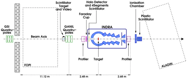
At high incident energies as 600, 1000, and 1800 AMeV, the main beam, vetoed with the halo detectors, was accompanied during the experiment by a component of beam particles that arrived at large distance from the beam axis, as it is sketched in Fig. 2.8. Fig. 2.7 presents the ‘good’ (which means not detected by the halo detector) event distribution and the ‘halo’ event distribution as functions of the charged particle multiplicity Nc. The two main features of the
‘halo’ events is their low multiplicity and their increasing amount with the increasing incident energy. The ‘halo’ presents two components for the energies 95 to 1000 AMeV. The high energy component comes from the events produced by projectiles hiting the thin inner ring of 1mm radius of the halo detector and the target without touching the INDRA structure. These events are vetoed by the halo detectors and rejected from the event selection.
y -0.2 0 0.2 0.4 0.6 0.8 1 1.2 x -0.6 -0.4 -0.2 0 0.2 0.4 0.6 1 10 102 103 104 95 AMeV yt ycm yp y -0.2 0 0.2 0.4 0.6 0.8 1 1.2 x -0.6 -0.4 -0.2 0 0.2 0.4 0.6 1 10 102 103 104 300 AMeV yt ycm yp y -0.2 0 0.2 0.4 0.6 0.8 1 1.2 x -0.6 -0.4 -0.2 0 0.2 0.4 0.6 1 10 102 103 104 600 AMeV yt ycm yp y -0.2 0 0.2 0.4 0.6 0.8 1 1.2 x -0.6 -0.4 -0.2 0 0.2 0.4 0.6 1 10 102 103 104 1000 AMeV yt ycm y -0.2 0 0.2 0.4 0.6 0.8 1 1.2 x -0.6 -0.4 -0.2 0 0.2 0.4 0.6 1 10 102 103 104 1800 AMeV yt ycm
Invariant Rapidity Spectra Lithium, C+Au
Figure 2.6: Invariant rapidity spectra of lithium fragments for the reactions C+Au at 95, 300, 600, 1000, and 1800 AMeV (inclusive data). The X-coordinate is the rapidity defined by the equation 2.1, the Y-coordinate is x = p⊥/m. The large circle corresponds to the target and the little circle visible for 95
and 300 AMeV is the projectile. The first vertical dotted line from the left indicates the target rapidity ‘yt’, the second one the rapidity of the center of mass ‘ycm’, and the third one the projectile rapidity ‘yp’.
1 102 104 1 102 104 1 102 104 1 102 104 20 40 60 1 102 104 0 20 40 60 C+Au at 1800 AMeV C+Au at 1000 AMeV C+Au at 600 AMeV C+Au at 300 AMeV C+Au at 95 AMeV Nc Nc event number
Figure 2.7: ‘Good’(full line) and ‘halo’ (dashed line) event distributions as function of the charged particle multiplicity Nc for the systems C+Au at 95, 300, 600, 1000, and 1800 AMeV.
✁ ✁ ✁ ✂ ✂ ✂ ✄✁✄ ✄✁✄ ✄✁✄ ☎ ☎ ☎ target main beam halo detector INDRA detector secondary beam
Figure 2.8:Schematical setup of the INDRA detector with a view of the stray particles punching through the halo detector or directly the backward rings of the detector.
The beam component coming from scatterings in the beam line is not detected by the halo detectors as it touches mainly the backward rings of INDRA beyond the aluminium structure of the halo detectors (see Fig. 2.8). These stray particles may react with the technical structure or the telescopes themselves. It leads to particle emissions with a low multiplicity and an increasing rate with the increasing beam energy. These particles are light particles and light ions as lithium fragments.
This background is visible in the rapidity spectra of lithium fragments for a carbon beam at the incident energy of 1000 AMeV, as shown in the Fig. 2.9. The left panel corresponds to reac-tions with a gold target and the right panel to reacreac-tions without target. The fifth plot (bottom left) of the both panels presents the peripheral collisions with the reduced impact parameter b/b0=0.8-1.0. The reduced impact parameter is here determined from the charged particle mul-tiplicity according to the selection method explained in the next chapter 4. These plots present in both cases a large circle accompanied by a narrower one for the reactions with a gold target. The large circle corresponds to stray particle effects while the narrow circle comes from reactions in the target. -0.5 0 0.5 0.0-0.2 -0.5 0 0.5 0.2-0.4 -0.5 0 0.5 0.4-0.6 x=p_t/mc2 -0.5 0 0.5 0.6-0.8 -0.5 0 0.5 0 0.5 1 0.8-1.0 y=1/2ln{(E+p//)/(E-p//)} -0.5 0 0.5 0 0.5 1 inclusive Lithium, C+none at 1000 AMeV
-0.5 0 0.5 0.0-0.2 -0.5 0 0.5 0.2-0.4 -0.5 0 0.5 0.4-0.6 x=p_t/mc2 -0.5 0 0.5 0.6-0.8 -0.5 0 0.5 0 0.5 1 0.8-1.0 y=1/2ln{(E+p//)/(E-p//)} -0.5 0 0.5 0 0.5 1 inclusive Lithium, C+none at 1000 AMeV
Figure 2.9:Rapidity spectra of lithium for an incident energy of 1000 AMeV as a function of the reduced impact parameter from central collisions (0.0-0.2) to peripheral reactions (0.8-1.0). The inclusive spectra are also presented. The left panel corresponds to reactions with a Au target and the right panel to reactions without target.
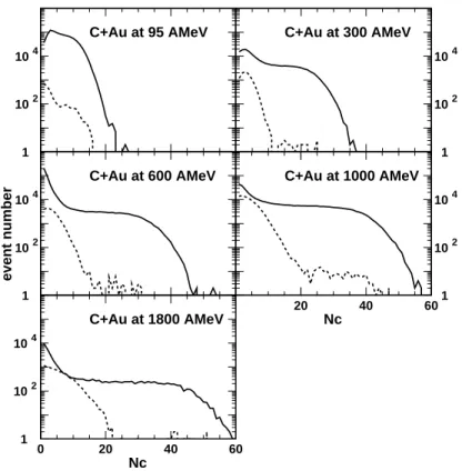
The case of the lithium fragments allows an easy analysis by cutting the higher energy part of the particles with an appropriate choice of the energy limit. This method will be used for the light ions in the analysis of fragment emission (see chapter 6). For the protons, produced in large quantities by reactions with and without target, the analysis of the most peripheral collisions needs a correction. It can be done by subtraction of the ‘no target’ spectra from the ‘good’ spectra with the application of a normalization factor, i.e. the ratio of event numbers counted in the halo detectors in both cases. This technique is usually applied in spectroscopy [Jon01, Jon02]. Fig. 2.10 presents original and corrected proton kinetic energy spectra for very peripheral collisions at 3o ≤ θ
lab ≤ 176o. The correction lowers the spectra yield by maximum
a factor 5 for the backward angles for a kinetic energy close to 100 MeV. The results involving light particles and pions presented in the chapters 5 and 7 are corrected following the procedure indicated above.