HAL Id: tel-02481986
https://hal.inria.fr/tel-02481986
Submitted on 17 Feb 2020HAL is a multi-disciplinary open access archive for the deposit and dissemination of sci-entific research documents, whether they are pub-lished or not. The documents may come from teaching and research institutions in France or
L’archive ouverte pluridisciplinaire HAL, est destinée au dépôt et à la diffusion de documents scientifiques de niveau recherche, publiés ou non, émanant des établissements d’enseignement et de recherche français ou étrangers, des laboratoires
Fog Infrastructures
Arif Ahmed
To cite this version:
Arif Ahmed. Efficient Cloud Application Deployment in Distributed Fog Infrastructures. Operating Systems [cs.OS]. Université de Rennes 1, France, 2020. English. �tel-02481986�
THÈSE DE DOCTORAT DE
L’UNIVERSITE DE RENNES 1
COMUE UNIVERSITE BRETAGNE LOIRE Ecole Doctorale N° 601
Mathématiques et Sciences et Technologies de l’Information et de la Communication Spécialité : Informatique
Par
«
Arif AHMED »
«
Efficient Cloud Application Deployment in Distributed Fog Infrastructures »
Thèse présentée et soutenue à RENNES, le 20 janvier 2020 Unité de recherche : IRISA (UMR 6074)
Thèse N° :
Rapporteurs avant soutenance :
Paolo BELLAVISTA, professeur, Université de Bologne (Italie) Frédéric DESPREZ, directeur de recherche, Inria
Composition du jury :
Président : Paolo BELLAVISTA, professeur, Université de Bologne (Italie)
Examinateurs :
Lydia CHEN, professeure associée, TU Delft (Pays-Bas)
Gene COOPERMAN, professeur, Northeastern University (Etats-U7nis) Frédéric DESPREZ, directeur de recherche, Inria
Shadi IBRAHIM, chargé de recherche, Inria
A
CKNOWLEDGEMENT
I would like to sincerely express my deepest gratitude to my supervisor, Profes-sor Guillaume Pierre, for his immense support, invaluable guidance, supervision and encouragement throughout this research. His dynamism, vision and motivation have deeply inspired me. He has taught me the methodology to carry out the research and to present the research work as clearly as possible. It was a great privilege and honor to work under his guidance. Thereafter, I am deeply grateful and obligated to Profes-sor Gene Cooperman, Northeastern University, US, for inviting me to go through an internship under his supervision and for guiding me with his invaluable knowledge.
I would also like to thank Christine Morin, Inria, Senior Scientist, and Shadi Ibrahim, Inria, Research Scientist for accepting to be the CSID Committee Members of my the-sis. Their thorough evaluation, suggestions and comments with encouraging words has assisted me to improve and complete the research report.
My heartfelt gratitude to all the jury members of the thesis for taking interest on my research work, especially, Professor Paolo Bellavista, University of Bologna, Italy and Frédéric Desprez, Inria, Senior Researcher, for reviewing the thesis and giving invaluable comments, which has helped me to improve the research report.
I thank my fellow and former members of MYRIADS team, who have always sup-ported me and boosted up my confidence anytime. I also want to thank Apoorve Mo-han, PhD Student, Northeastern University, US for his support while moving to North-eastern University, US and the technical support I received during my Internship work. Special thanks to my wife, Firoza Choudhury, for being the pillar of strength, for always believing in me and motivating me with love and support, and my family and friends who have always stood beside me with their endless love and support during my PhD journey.
R
ESUMÉ
Les architectures de cloud computing sont composées d’un grand nombre de serveurs puissants connectés les uns aux autres et au reste de l’Internet avec liens réseau à grande vitesse. La latence entre un utilisateur final et le centre de données cloud le plus proche se situe dans une plage de 20 à 40 ms sur les réseaux filaires, et jusqu’à 150 ms sur les réseaux mobiles 4G. Bien que cette latence soit acceptable pour de nombreuses applications, elle crée de nombreux défis pour certains types d’applications comme par exemple les applications sensibles à la latence telles que les applications de réalité augmentée. Ces applications exigent une latence de bout en bout, y compris le délai de traitement et de réseau, de moins de 10-20 ms. Un autre exemple de telles applications est l’analyse de données IoT. Le nombre crois-sant de dispositifs IoT produit chaque jour de grandes quantités de données. Les don-nées collectées sont généralement envoyées au cloud pour analyse ultérieure, ce qui consomme une grande quantité de trafic Internet mondial. Une solution possible pour relever ces défis consiste à héberger les applications à proximité des utilisateurs fin-aux. Les infrastructures de type Fog computing étendent donc les ressources du cloud (calcul, stockage et réseau) en distribuant largement un grand nombre de nœuds à proximité des utilisateurs finaux. Par conséquence, la capacité de calcul est toujours disponible à proximité des utilisateurs.
Les architectures informatiques de Fog computing sont composées d’un grand nombre de nœuds informatiques dispersés dans une zone géographique telle qu’une ville, une région ou même un pays entier afin de maintenir la proximité avec un grand nombre d’utilisateurs. En conséquence, les ressources Fog sont souvent organisées en un grand nombre de points de présence (PoP), où chaque PoP est composé d’un petit nombre de machines faibles, telles que des nano-ordinateurs connectés les uns aux autres et au reste de l’Internet avec des réseaux hétérogènes. Un utilisateur fi-nal accède toujours aux applications depuis le point de présence le plus proche pour maintenir une latence minimale.
Nous prévoyons que les applications Fog seront déployées à plusieurs reprises dans différents PoPs : pour maintenir une latence minimale entre les applications
d’être aléatoire, et il a été prouvé qu’elle est prévisible malgré des différences impor-tantes entre les habitudes de déplacement individuelles. Les applications Fog telles que l’assistance cognitive portable qui vise à servir un seul utilisateur avec une latence ultra-faible peuvent donc être déployées de manière répétée dans le même PoP que l’utilisateur visite souvent (à la maison, au travail, etc.). Dans un autre exemple, des applications de calcul intensif telles que l’analyse de flux vidéo en direct peuvent avoir besoin de déployer plusieurs instances identiques dans le même PoP afin de passer horizontalement leur capacité de traitement à l’échelle. Dans ces scénarios, le proces-sus de déploiement d’application ne peut pas être considéré comme une opération unique qui n’affecte pas la qualité d’expérience de l’utilisateur final. Au contraire, il de-vient une partie intégrante du chemin critique vers la fourniture du service attendu par les utilisateurs.
Le déploiement lent d’applications est donc un problème difficile dans les infras-tructures Fog. Tout retard dans le déploiement de l’application peut forcer l’utilisateur à attendre que l’application ait été entièrement déployée et soit prête à servir ses util-isateurs. Lorsque l’utilisateur passe d’un PoP à un autre, il peut être nécessaire de redéployer l’application pour maintenir une faible latence d’accès et réduire le trafic réseau longue distance. Dans ces cas, tout retard dans le déploiement de l’application peut interrompre le service en cours d’exécution, conduisant à une dégradation de la qualité d’expérience (QoE) de l’utilisateur. Dans les deux scénarios, un temps de déploiement d’applications minimal est essentiel pour fournir des services cloud trans-parents aux utilisateurs finaux. Cette thèse vise donc à réduire autant que possible le temps de déploiement des applications des applications Fog.
Nous avons étudié les raisons de la lenteur de déploiement des conteneurs Docker dans des environnements Fog distribués, et identifié trois opportunités susceptibles de réduire le temps de déploiement des conteneurs: (1) améliorer le taux de réus-site du cache Docker, ce qui réduit les chances d’avoir à instalelr une nouvelle image; (2) accélérer l’opération d’installation d’une image; et (3) accélérer le processus de démarrage après la création d’un conteneur. Nous avons donc proposé trois solutions différentes pour optimiser le temps de déploiement global des applications. Chaque so-lution vise à résoudre l’un des problèmes ci-dessus dans le processus de déploiement.
Contribution 1: Améliorer le taux de réussite du cache Docker
La première contribution de la thèse est d’améliorer le temps de déploiement des applications en réduisant la probabilité d’avoir à installer de nouvelles images lors d’une demande de déploiement d’un conteneur. Les serveurs Docker téléchargent une im-age depuis un registre distant chaque fois qu’ils constatent que le l’imim-age requise n’est pas disponible dans le cache local. Docker stocke toutes les images téléchargées dans son cache local et ne les supprime jamais jusqu’à ce que soit explicitement demandé. C’est une stratégie judicieuse pour les serveurs puissants car la même image de con-teneur ne devra pas être téléchargée à nouveau lors d’un futur déploiement du même conteneur. Cependant, ce scénario ne convient pas dans les environnements Fog, car les serveurs Fog ont une capacité de stockage limitée. En conséquence, l’ensemble de travail des images fréquemment utilisées peut dépasser la capacité de stockage to-tale du serveur. Un autre problème est que les caches Docker des nœuds co-localisés peuvent contenir des copies redondantes des mêmes images.
Nous proposons un nouveau système de partage d’images Docker qui regroupe les caches des serveurs Fog co-localisés grâce à un système de fichiers partagé. Le résultat final est un cache d’image Docker beaucoup plus volumineux qui peut donc partager plus d’images, ce qui réduit la probabilité de déploiement d’un nouvelle image lors du déploiement d’un conteneur. Notre évaluation de ce système basé sur des traces réelles de registres Docker montre que le partage des images Docker peut considérablement améliorer le taux de réussite du cache et, par conséquent, réduire le temps de déploiement des conteneurs entre 37% et 78% selon le scénario.
Contribution 2: Amélioration du déploiement des images Docker
Le partage d’images Docker entre des serveurs co-localisés améliore le taux de réussite du cache d’images Docker et réduit la probabilité que l’image doive être in-stallée lors d’une demande de déploiement d’un conteneur. Cependant, Docker doit encore déployer les images quand leur déploiement est demandé pour la première fois dans un POP, ou lors d’un défaut du cache. Le déploiement d’images Docker peut être très lent, dans l’ordre de plusieurs minutes dans des nœuds Fog aux ressources lim-itées tels que les nano-ordinateurs Raspberry Pi. Nous avons étudié la raison de cette lenteur de déploiement en analysant la consommation de ressources de Docker lors d’un déploiement. Nous avons constaté que cette lenteur est en grande partie due au
en ressources réseau. Docker lance ensuite un cycle de décompression de l’image, qui est gourmande en ressources processeur. Enfin l’extraction de l’image est gour-mande en ressources d’entrées/sorties disque. En d’autres termes, il y a peu ou pas de chevauchement entre l’utilisation des différences ressources matérielles durant le déploiement de l’image.
Nous avons proposé trois optimisations pour améliorer l’utilisation de ressources lors du déploiement d’images: (1) télécharger les couches d’images séquentiellement pour optimiser le temps de téléchargement; (2) décompression multi-thread pour ré-duire le temps de décompression des couches; et (3) organiser le processus en pipeline d’entrées/sorties pour commencer à décompresser les couches immédiate-ment après le téléchargeimmédiate-ment des premiers octets. Docker-pi combine toutes ces solu-tions et par conséquent parallélise l’utilisation des trois ressources matérielles (réseau, processeur et disque), ce qui permet de réduire le temps de déploiement des images de 25% à 75% dans des Raspberry Pis en fonction de la capacité du réseau et de la taille de l’image.
Contribution 3: éviter la phase de démarrage du conteneur
Après avoir créé un conteneur, Docker lance la phase de démarrage en lançant le processus initial de l’application. Le démarrage se termine lorsque le conteneur est prêt à accepter les requêtes de l’utilisateur final. Cette phase peut avoir un impact significatif dans des environnements Fog lorsque la même image de conteneur est lancée à plusieurs reprises sur plusieurs serveurs d’un point d’accès. La phase de démarrage des conteneurs reste cependant identique à chaque démarrage. On peut donc sauvegarder l’état d’un conteneur après qu’il ait terminé sa phase de démarrage, et redémarrer le conteneur à partir de l’état sauvegardé lors des déploiements suivants. Nous avons proposé un nouveau concept de déploiement de conteneurs utilisant DMTCP qui permet de déployer un conteneur à partir d’une image sauvegardée d’un conteneur démarré, ce qui permet d’éviter la phase de démarrage du conteneur. Ce système utilise Ceph afin the partager efficacement les images entre plusieurs serveurs Fog d’un même PoP. Notre évaluation montre que cette technique améliore
la durée de la phase de démarrage d’un conteneur jusqu’à 60x selon le type de con-teneur. Les surcoûts d’exécution de ce système restent raisonnables.
A
BSTRACT
Cloud computing architectures consist of large number of powerful servers con-nected to each other and to the rest of the Internet with high-speed network links. The latency between a typical end user and the closest cloud data center comes in the range of 20-40 ms over wired networks, and up to 150 ms over 4G mobile networks. Although this latency is acceptable for many applications, it creates many challenges for certain types of applications: for example, latency-sensitive applications like aug-mented reality games require an end-to-end latency including network and processing delay under 10-20 ms. Another example of such applications is IoT data analysis. The growing number of IoT devices produces large amounts of data every day. The col-lected data is typically sent to the core-cloud for further analysis. which consumes large amount of global Internet traffic. An obvious solution to address these challenges is to host applications near the end users. Fog computing therefore extends the cloud resources (compute, storage and network) by broadly distributing large numbers of compute nodes near the end users. Therefore, computational capacity is always avail-able in the vicinity of the users.
In contrast, Fog computing architectures consist of large number of computing nodes dispersed across a geographical area such as a city, a region or even a country to maintain proximity with a large number of users. As a consequence, fog resources are often organized in a large number of Point-of-Presence (PoP), where each PoP is composed of a small number of weak machines such as single-board computers con-nected to each other and to the rest of the Internet using heterogeneous networks. An end user always accesses the applications from the closest PoP to maintain minimal latency.
We expect that fog applications will be repeatedly deployed in different PoPs: to maintain minimum latency between the applications hosted in the fog and their end users, applications may need to roam frequently from one PoP to another. Human mobility remains far from being random, and it has been proven to be predictable de-spite important differences between individual travel patterns. Fog applications such as wearable cognitive assistance which aims at serving a single user with ultra-low
video feed analysis may need to deploy multiple identical instances in the same PoP in order to horizontally scale their processing capacity. In these scenarios, the appli-cation deployment process cannot be considered as a one-time operation which does not affect the end-user’s quality of experience. Rather, it becomes an integral part of the critical path towards providing the expected service to its end users.
Slow application deployment is therefore a challenging issue in fog infrastructures. Any delay in the application deployment may force the user to wait until the application has been fully deployed and is ready to serve users. When the user moves from one PoP to another, the application may have to be re-deployed to maintain proximity, low latency, and reduce long-distance traffic. In such cases, any delay in the application deployment may interrupt the already-running service, leading to a degradation of the user’s Quality-of-Experience (QoE). In both scenarios, a minimal application deploy-ment time is essential to provide seamless cloud services to the end-users. This thesis therefore aims to reduce the application deployment time of fog applications as much as possible.
We studied the reasons behind the slow deployment time of Docker containers in distributed fog infrastructures, and identified three opportunities that are likely to speed up the container deployment time: (1) Improving the hit ratio of the Docker cache, which reduces the chances of having to pull a new image; (2) Speeding up the image pull operation itself; and (3) Speeding up the boot process after a container has been started. We therefore proposed three different solutions to optimize the overall appli-cation deployment time. Each solution aims to address one of the above issues within the deployment process.
Contribution 1: Improving the Docker cache hit ratio
The first contribution of the thesis is to improve the application deployment time by reducing the probability of having to deploy new images upon container deployment requests. Docker servers download an image from a registry whenever they find that the required image is missing in the local cache. Docker stores all the downloaded images in its local cache and never removes them until explicitly asked for. This is a sensible strategy in powerful servers as the same container image will not need to be
downloaded again in future deployment of the same container. However, this scenario is not suitable in fog environments, as fog servers have limited storage capacity. As a consequence, working set of images may grow larger than the total storage capacity of the server. Another issue is that the image caches of the co-located nodes may contain redundant copies of the same images.
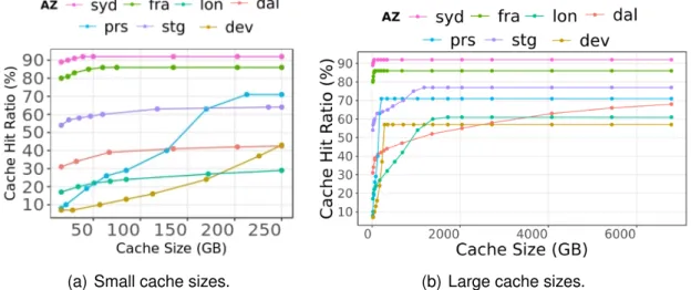
We proposed a new Docker image sharing framework which aggregates the im-age caches of co-located fog servers using a distributed file system. The end result is a much larger Docker image cache that can share more images, which reduces the probability of deploying a new image upon a container deployment request. Our performance evaluation of the proposed framework using a real-world Docker registry workload shows that sharing the Docker images can significantly improve the hit ratio and, as a result, reduce container deployment time between 37% and 78% depending on the scenario.
Contribution 2: Improving the Docker image deployment
Sharing Docker images among co-located servers enhances the Docker cache hit ratio and reduces the probability of image pull upon a container deployment request. However, Docker still needs to deploy an image when it is requested for the first time in a PoP or upon a cache miss. Docker image deployment can be very slow, in the order of a couple of minutes in resource-constrained fog nodes such as single-board Raspberry Pi. We investigated the reason behind this slow deployment by analyzing the resource consumption of Docker upon a image deployment. We found that this slow deployment time is largely due to the fact that Docker under-utilizes the available hardware resources during deployment: Docker first downloads the different image layers simultaneously which is very network intensive, followed by a cycle of CPU-intensive decompression and then disk-CPU-intensive extraction. In other words, there is little or no overlapping among the usage of different hardware resources during the image deployment.
We proposed three optimizations to improve the resource utilization of Docker dur-ing image deployment: (1) Sequentially downloaddur-ing the image layers to optimize layer download time; (2) Multi-threaded decompression to reduce the decompression time of layers; and (3) I/O pipelining to decompress the layers immediately after the first few bytes have been downloaded. Docker-pi combines all these solutions and therefore
on the network capacity and the image size.
Contribution 3: Avoiding the container boot phase
After creating a container, Docker starts the boot phase by launching the starting process of the application. Booting terminates when the container is ready to accept end user requests. This phase may have a significant impact in fog environments when the same container image is being repeatedly launched, created, and booted in multi-ple servers of a PoP. The boot phase of containers however remains the same every time. We can therefore save the state of a container after completing its boot phase and then later restart the container from the saved state in the subsequent deployments.
We proposed a new container deployment design which uses DMTCP to deploy the container from a booted checkpoint image, therefore skipping the container boot phase. The design uses Ceph distributed storage to store container environments and checkpoint images to efficiently share them across fog servers. Our evaluation shows that this technique improves the container boot phase time up to 60x depending on the type of container. The checkpointing overhead of the proposed system remains reasonable.
T
ABLE OF
C
ONTENTS
1 Introduction 23
1.1 Contributions . . . 26
1.2 Published papers related to the thesis . . . 29
1.3 Organization of the thesis . . . 29
2 Background 31 2.1 Cloud computing . . . 31
2.1.1 Cloud computing architecture . . . 31
2.1.2 Limitations of cloud computing . . . 32
2.2 Approaches to address cloud computing limitations . . . 33
2.2.1 Fog computing definitions . . . 34
2.2.2 Fog computing architecture . . . 35
2.2.3 Application deployment frameworks in fog computing . . . 36
2.3 Docker . . . 38
2.3.1 Docker architecture . . . 39
2.3.2 Docker images . . . 40
2.4 Application deployment inside Docker containers . . . 45
3 State of the art 49 3.1 Introduction . . . 49
3.2 Speeding up the Docker image deployment . . . 50
3.2.1 Server-side approaches . . . 50
3.2.2 Client-side approaches . . . 52
3.3 Avoiding image deployment . . . 54
3.4 Speeding up container creation . . . 55
3.5 Speeding up the container boot phase . . . 56
4 Improving the Docker Cache Hit Ratio 59
4.1 Introduction . . . 59
4.2 Potential benefit of cache sharing . . . 61
4.2.1 Simulation setup . . . 61
4.2.2 Cache hit ratio analysis . . . 63
4.3 System design . . . 64
4.3.1 Choice of distributed file system . . . 65
4.3.2 Sharing Docker images . . . 68
4.3.3 Consistency maintenance of in-memory metadata . . . 69
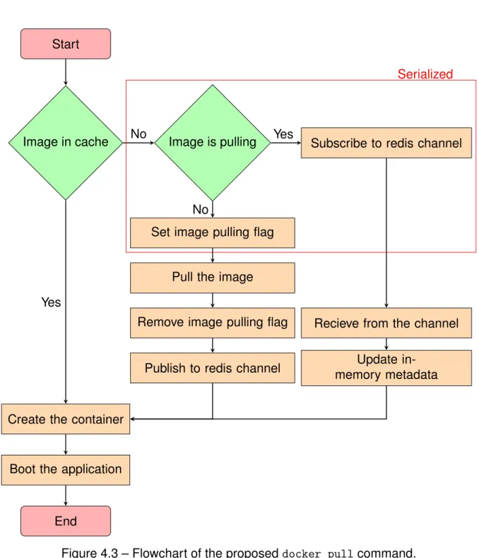
4.3.4 Preventing concurrent deployments of the same image . . . 70
4.3.5 Cache replacement . . . 72
4.4 Evaluation . . . 73
4.4.1 Micro-benchmarks . . . 73
4.4.2 Simultaneous Application Deployment . . . 77
4.4.3 Macro-benchmarks . . . 78
4.5 Conclusion . . . 80
5 Speeding Up the Docker Image Deployment 83 5.1 Introduction . . . 83
5.2 Understanding the Docker container deployment process . . . 84
5.2.1 Experimental setup . . . 84
5.2.2 Monitoring the Docker container deployment process . . . 86
5.2.3 Critical observations . . . 88
5.3 Optimizing the container deployment process . . . 90
5.3.1 Sequential image layer downloading . . . 90
5.3.2 Multi-threaded layer decompression . . . 93
5.3.3 I/O pipelining . . . 96
5.3.4 Docker-pi . . . 99
5.4 Discussion . . . 102
5.4.1 Should we flatten all Docker images? . . . 102
5.4.2 Does Docker-pi work also for powerful server machines? . . . . 103
5.5 Conclusion . . . 104
6 Avoiding the Container Boot Phase 107 6.1 Introduction . . . 107
6.2 State of the art . . . 109
6.3 Design issues . . . 112
6.3.1 Integration of DMTCP with Docker . . . 112
6.3.2 Sharing container environments . . . 113
6.3.3 Sharing the checkpoint images . . . 113
6.4 Proposed container deployment design . . . 114
6.4.1 DMTCP lightweight containers . . . 115
6.4.2 Ceph block devices . . . 115
6.4.3 Container deployment with checkpoint/restart . . . 119
6.5 Evaluation . . . 121
6.5.1 A use-case: Edge-sharelatex . . . 121
6.5.2 Checkpointing overhead . . . 122
6.5.3 Boot phase time . . . 123
6.5.4 Communication within the Ceph cluster . . . 124
6.5.5 Interference with other applications . . . 126
6.6 Conclusion . . . 127
7 Conclusion and Future Work 129 7.1 Conclusion . . . 129
7.1.1 Contribution 1: Improving the Docker cache hit ratio . . . 131
7.1.2 Contribution 2: Improving the Docker image deployment . . . 131
7.1.3 Contribution 3: Avoiding the container boot phase . . . 132
7.2 Future directions . . . 133
7.2.1 Finding a better cache replacement algorithm . . . 133
7.2.2 Image layer placement in the distributed file system . . . 133
7.2.3 Pre-fetching Docker images . . . 134
L
IST OF
F
IGURES
1.1 Flowchart of Docker application deployment process. . . 26
2.1 Cloud computing architecture. . . 32
2.2 Distributed fog computing architecture. . . 35
2.3 Multiple Docker containers running in a same host machine (adapted from [91]). . . 39
2.4 Docker architecture (adapted from [93]). . . 39
2.5 Dockerfile for creating “stream:1.0” Docker image. . . 41
2.6 Structure of “stream:1.0” Docker image. . . 41
2.7 Docker storage directory. . . 44
2.8 Multiple container images sharing the same underlying layers (adapted from [87]). . . 45
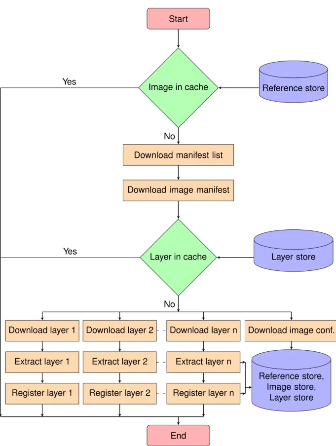
2.9 Flowchart of the Docker docker pull image deployment process. . . . 46
3.1 Docker container deployment optimizations. . . 58
4.1 Cache hit ratios of different AZs vs. shared cache size. . . 62
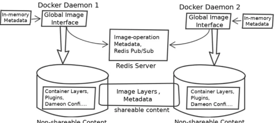
4.2 Docker shared image cache architecture. . . 64
4.3 Flowchart of the proposed docker pull command. . . 71
4.4 Resource utilization upon a cache miss. . . 76
4.5 Resource utilization upon a cache hit. . . 76
4.6 Overhead of simultaneous container deployments. . . 78
4.7 Hit ratio of shared vs. non-shared image caches under a workload of 4000 container deployments. . . 79
4.8 Deployment time of shared vs. non-shared image caches under a work-load of 4000 container deployments. . . 81
5.1 Structure of the “Mubuntu” container image. . . 85
5.2 Deployment times and resource usage using standard Docker. . . 87
5.6 Resource usage and deployment time with multi-threaded image layer
decompression. . . 95
5.7 Docker pull operation with I/O pipelining. . . 97
5.8 Deployment time and resource usage with I/O pipelining. . . 98
5.9 Resource usage and deployment time with Docker-pi. . . 100
5.10 Memory footprint of Docker and Docker-pi during container deployment. 101 5.11 Upload throughput of the Apache web server. . . 102
5.12 Deployment time of Docker and Docker-pi in Grid’5000. . . 104
6.1 Contents of a container environment and a DMTCP checkpoint image . 113 6.2 Proposed container deployment with DMTCP . . . 114
6.3 Snapshot and clone feature of Ceph . . . 117
6.4 Container environment layering with snapshot and clone . . . 118
6.5 How block device is mounted in container file system . . . 119
6.6 Flowchart of the Docker container deployment with DMTCP. . . 120
6.7 Checkpoint image size and checkpointing time of the services. . . 123
6.8 Network throughput of the nodes when the system is: (a) idle; (b) check-pointing and (c) restarting. . . 125
L
IST OF
T
ABLES
2.1 Different characteristics of fog computing and cloud computing. . . 37
2.2 Fog application deployment frameworks . . . 37
4.1 Registries used in the simulations. . . 61
4.2 Comparison of popular distributed file systems. . . 66
4.3 Distributed file system configurations. . . 74
4.4 Deployment times of an ubuntu:latest container. . . 74
5.1 Structure of the Docker images. . . 85
6.1 Name of the services and their purpose. . . 122 6.2 Boot phase time of the services with standard Docker and the proposed
model. . . 124 6.3 Throughput of the HTTP service in the standard Docker and proposed
CHAPTER1
I
NTRODUCTION
Cloud computing relies on large numbers of powerful computing nodes connected to each other and to the rest of the Internet with reliable high-capacity networks. The combination of flexibility, scalability and manageable cost of cloud infrastructures dic-tated the immense popularity of this new computing paradigm. However, cloud re-sources are concentrated in a small number of data centers, usually far from the end-users they are serving. The latency between an end user and the closest available cloud data center is typically in the range of 20-40 ms over wired networks, and up to 150 ms over 4G mobile networks [44]. Although this is perfectly acceptable for a wide range of useful applications, a number of latency-sensitive applications such as augmented reality games require end-to-end latency including network and process-ing delay under 10-20 ms [1, 30]. These constraints make it impossible to host such latency-critical application backends in the cloud. In another use case, the growing number of Internet of Things (IoT) devices produces a large volume of sensor data ev-ery day [42]. Sending all the collected data to the core cloud using long-distance Wide Area Networks (WAN) for further processing would consume enormous amount of net-work resources [15]. An obvious solution to address these problems is to place cloud server nodes extremely close to the users, within a couple of network hops. In fog com-puting, computational nodes are broadly distributed in a large number of geographical locations so computation capacity is always available in immediate proximity of any end user. Fog computing promises to deliver low latency between the end users and their application and to reduce the usage of long-distance networks. Some other examples of using fog computing for different purposes include: privacy and security [159], ser-vice management [135], computational offloading [139], serser-vice monitoring [126] and content caching [133].
Fog computing architectures are fundamentally different from traditional cloud ar-chitecture: to maintain proximity with a large number of users, fog resources must nec-essarily be dispersed across a large geographical area such as a city, a region or even
an entire country [32]. In contrast, clouds are typically organized with a handful of ex-tremely powerful data centers connected to each other by dedicated ultra-high-speed networks. As a consequence, fog resources are often organized in a large number of Points-of-Presence (PoPs) dispersed across the covered area. Each PoP may be com-posed not of datacenter-grade servers but rather of a small number of resource-limited nodes such as single-board computers which are connected to each other and with the rest of the Internet using heterogeneous commodity networks [75, 153]. Users usually connect to the closest PoP in order to access the services offered by the fog platform.
Fog applications must often be repeatedly deployed in different fog servers: in par-ticular, to maintain proximity between the applications deployed in the fog and their end users, applications may need to roam frequently from one PoP to another, whereas cloud applications are usually placed in one or more dedicated machines irrespective of users’ mobility [28]. The mobility of human beings is far from being random, and it has been shown that despite significant differences between individual travel patterns, user mobility remains remarkably repetitive and predictable [25, 175]. A fog application such as wearable cognitive assistance which aims at serving a single user with ultra-low la-tency may therefore repeatedly deploy the application in the same server locations the user visits often (home, work, etc.) [74] . In another case, compute-intensive applica-tions such as live video feed analysis may need to deploy multiple identical instances in the same PoP in order to horizontally scale its processing capacity [208]. In these scenarios, the application deployment process cannot be considered as a one-time op-eration which does not affect the end-user’s quality of experience. Rather, it becomes an integral part of the critical path towards providing the expected service to its end users.
Slow application deployment is therefore a challenging issue in fog infrastructures. Any delay in the application deployment may force the user to wait until the application is being fully deployed and ready to serve users. When the user moves, the applica-tion may have to be re-deployed in multiple fog PoPs to maintain proximity, low latency, and reduce long-distance traffic. In such cases, any delay in the application deploy-ment may interrupt the already-running service, leading to a degradation of the user Quality-of-Experience (QoE). In both scenarios, a minimal application deployment time is essential to provide seamless cloud services to the end-users. This thesis there-fore aims to reduce the application deployment time of fog applications as much as possible. We define application deployment time as:
"The time elapsed after giving the application deployment instruction until the appli-cation is ready to serve users."
Docker is by far the most popular application deployment tool in fog environment [7]. It is widely used to deploy containers, either directly or via the use of distributed con-tainer orchestration frameworks such as Kubernetes [164]. Docker virtualizes hard-ware resources such as compute, network, storage resources with the help of special Linux kernel features [91]. The primary reasons for the increasing popularity of Docker containers are their lightweight nature, and the ease of encapsulating, deploying, and running applications. Instead of installing a full operating system inside a virtual ma-chine, all Docker containers in a single host machine share the underlying Linux kernel which makes container images much smaller and faster to deploy compared to virtual machine images [170]. In fog, which is often made of weak machines such as Rasp-berry Pis, resources have very limited processing, storage and I/O throughput [153]. In such environment, containers are considered the best tool for cloud application deploy-ment that give better performance over traditional virtual machines [123]. We therefore choose to use Docker as our basis for studying the cloud application deployment in fog computing environment.
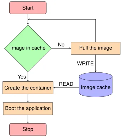
Figure 1.1 shows a flowchart of the Docker application deployment process. Appli-cation deployment starts by giving the container deployment instruction with the ap-plication image name and tag and other container configuration. Docker maintains an image cache in the local disk of the server where images and other configurations are stored. Upon receiving the deployment command, Docker first checks whether the im-age of the application is already present in the local cache. If the imim-age is not cached, Docker triggers the image pull command with the name and tag of the image. The de-ployment starts by downloading all the layers of the image from a registry server and finally building the image. Once the image is available in the local cache, Docker then creates a container file system on top of the image and creates the container with the given configuration. The application finally needs to start before being able to serve its users. Some applications such as mysql require significant amount of time to boot before being ready to server their end-users.
Within this application deployment process, we identify three opportunities that are likely to speed up the application deployment: (a) Improving the hit ratio of the Docker cache, which reduces the chances of having to pull a new image; (b) Speeding up the image pull operation itself; (c) Speeding up the boot process of the container. We
Start
Image in cache Pull the image
Create the container
Boot the application
Stop Image cache No Yes WRITE READ
Figure 1.1 – Flowchart of Docker application deployment process.
therefore propose three different solutions to optimize the overall application deploy-ment time. Each solution aims to address one the above issues within the deploydeploy-ment process. We now discuss each proposed contribution of the thesis.
1.1
Contributions
The main contributions of this thesis are as follows: — Contribution #1: Improving Docker’s cache hit ratio.
Docker was designed with the assumption it would mostly run in large-scale powerful machines. Docker stores all the running container images in the Docker cache of the local disk to avoid downloading the same image again in case the same container is deployed in the future. Because disk space is not expected to be an issue, Docker never removes the images from the cache unless explic-itly asked to do so. This design choice however creates an important storage
1.1 Contributions
issue in fog infrastructures where the servers have limited storage capacity and containers are frequently started and stopped. If the size of the working set of container images is greater than the server’s storage capacity then the same im-age may need to be repeatedly downloaded, utilized and deleted. Another effect of keeping separate Docker cache in each node is that the caches of multiple fog nodes in the same PoP may contain highly redundant content due to some popular images being deployed multiple times in different machines.
We therefore propose a new Docker image sharing framework that allows multi-ple fog nodes in the same PoP to share the content of their Docker images. In-stead of keeping a separate local Docker cache in each node, we aggregate the storage of co-located fog nodes in a PoP. The end result is a much larger cache for each PoP that can store more images, significantly reducing the chances of downloading the images from the long-distance network upon container deploy-ment. Our evaluation based on a real-world Docker registry deployment trace workload shows that sharing the images delivers significant cache hit ratio im-provements, leading to a reduction of deployment time between 37% and 78% depending on the scenario.
— Contribution #2: Speeding up the Docker image pull process.
Although sharing caches significantly improves the cache hit ratio, Docker still needs to download the images when applications are deployed for the first time in a PoP or upon a cache miss. Docker takes several minutes to deploy an image in a resource-constrained fog server such as single-board Rasp-berry Pi. This slow deployment however is not only due to the fact that these resource-constrained machines have limited processing, storage, I/O and net-work throughput. We show that Docker implementation inefficiencies creates unnecessary delay. The standard image deployment process starts by down-loading image layers from a registry server in parallel (with a default parallelism degree of 3) and then goes through multiple decompression and disk write cy-cles to extract the layers sequentially beginning from the first layer. The above process leads to three important issues in the image deployment: (a) Down-loading multiple layers in parallel delays the download process of the first layer and therefore, postpones the moment its decompression and extraction phase can start. Therefore, delaying the downloading of the first layer ultimately leads to slowing down the extraction phase; (b) Docker image layers are shipped as
compressed tar files. Upon downloading an image file, Docker decompresses it using single-threaded decompression gzip which account only for ∼37% CPU utilization of all the machine’s cores. A significant amount of deployment time is spent in decompressing the layers; (c) Each image layer is sequentially down-loaded, decompressed and extracted to disk. In other words, there is very little overlapping between the three activities of the different hardware resources (i.e. network, CPU and disk) while deploying the image.
To address the above issues, we propose three optimization solutions which ad-dress these issues in the standard Docker image deployment process. We then present Docker-pi which combines these optimizations together. We show that Docker-pi reduces the image deployment time by a factor of up to 4 depending on the size of the image and the available network bandwidth. Docker-pi also reduces the image deployment time by 23–36% in powerful data-center grade servers.
— Contribution #3: Reducing the container boot time.
Once an image is available in the local cache, Docker creates a container file system on top of the image and then creates the container itself with the given configuration. The application then needs to boot inside the container before being ready for usage. We found that creating a Docker container takes a neg-ligible amount of time (less than 1 s). However, the application boot process may take significant time for some applications: for example, the popular mysql database application takes about 10 s to boot the application before accepting user’s commands [142]. The significant boot time leads to slow down the appli-cation deployment.
To address the above issue, we propose a container deployment model that uses process checkpoint/restart to launch the application inside the container. The checkpoint/restart allows one to save the state of a running application by storing the process information of the application such as memory pages, open sockets and open files in a file or checkpoint image [129]. The application can then be restarted from the checkpoint image file and continue its execution from there on. We propose to use DMTCP to start the application upon creating the container and checkpoint it after completing the boot phase [10]. The resulting checkpoint image contains a full snapshot of the application after the boot phase. In later deployments DMTCP is instructed to launch the application from the
1.2 Published papers related to the thesis
checkpoint image, and therefore, skip the application boot phase. The evaluation of this proposed container deployment model based on Edge-sharelatex [182] has shown that it can reduce the boot time upon deployment which results in the improvement of container boot time by up to 60x times over the standard Docker with reasonable checkpoint overhead.
1.2
Published papers related to the thesis
The following manuscripts are currently published or under review: Journal articles
1. Docker-pi : Docker container deployment in Fog Computing Infrastructures,Arif
Ahmed and Guillaume Pierre, Inderscience International Journal of Cloud Com-puting, In press.
Conference papers
1. Docker Container Deployment in Distributed Fog Infrastructures with
Check-point/Restart, Arif Ahmed, Apoorve Mohan, Gene Cooperman and Guillaume
Pierre, The 8th IEEE International Conference on Mobile Cloud (IEEE Mobile
Cloud), Apr 2020, Oxford, UK.
2. Docker Image Sharing in Distributed Fog Infrastructures,Arif Ahmed and
Guil-laume Pierre, The 11th IEEE International Conference on Cloud Computing
Technology and Science (IEEE CloudCom), Dec 2019, Sydney, Australia.
3. Docker Container Deployment in Fog Computing Infrastructures, Arif Ahmed
and Guillaume Pierre, IEEE International Conference on Edge Computing (IEEE EDGE), Jul 2018, San Francisco, CA, United States.
Posters
1. Efficient Container Deployment in Edge Computing Platforms ,Arif Ahmed and
Guillaume Pierre, RESCOM 2017 summer school – Le Croisic, France. Jun 2017.
1.3
Organization of the thesis
Chapter 2 presents the technical background of the thesis. First, we present an overview of cloud computing and identify some of its limitations. We then define fog computing and explain how it addresses the limitations of cloud computing. Finally, we present an overview of Docker, describe its important components, and how applica-tions are deployed inside Docker containers.
Chapter 3 presents the state-of-the-art of the thesis. We first present the different opportunities to improve deployment process within the Docker container deployment processes. We then describe each of the proposed optimization solutions and also shows how our contributions complement them. Finally, we conclude the chapter by presenting a taxonomy of the state of the art of Docker container deployment optimiza-tions.
Chapter 4 starts by demonstrating the potential benefits of sharing individual Docker cache of fog servers in a PoP. We then identified different issues to build a shareable Docker image cache in fog computing environments. We then show how the proposed Docker image sharing framework addresses each issue. The chapter is concluded with the performance evaluation of the image cache sharing framework with two bench-marks: micro-benchmarks and macro-benchmarks in a fog environment testbed.
Chapter 5 illustrates the experimental study of Docker image deployment and then presents an analysis of resource utilization of Docker while an image is being deployed. We then show the incumbencies in Docker image deployment process which lead to slow image deployment. We then present the three optimization solutions and their performance improvement over the standard Docker. The chapter is concluded with an interesting discussion of Docker-pi in various aspects.
Chapter 6 presents the scope of checkpoint/restart tools in particular DMTCP to improve Docker container deployment. We then identify the different challenges while integrating DMTCP with Docker for container deployment. We present the proposed container deployment design. Finally the chapter is concluded by showing the perfor-mance evaluation of the our design with a use case.
Chapter 7 presents the conclusion of the thesis. We briefly remind the importance of application deployment time in distributed fog infrastructures. We then summarize the different contributions of the thesis to improve the application deployment time. Finally, we highlight the number of directions that we may study in the future to further reduce the application deployment time in distributed fog infrastructures.
CHAPTER2
B
ACKGROUND
This chapter presents the technical background of the thesis. First, we present an overview of cloud computing and identify some of its limitations. We then define fog computing and explain how it addresses the limitations of cloud computing. Finally, we present an overview of Docker, describe its important components, and how applica-tions are deployed inside Docker containers.
2.1
Cloud computing
Cloud computing is an IT organization paradigm that aims to provide resources (in-frastructure, platform, software) on-demand to customers [36, 72]. Traditionally, small and medium-sized enterprises had to own IT infrastructures and hire software devel-opers and system administrators to deploy services, which resulted in large costs of ownership. Cloud computing offers to deliver virtual resources (both hardware and soft-ware) that can be accessed from anywhere through Internet at a cost depending on the usage of the resources. With the advent of cloud computing, enterprises no longer have to own their IT infrastructures and other resources to deploy services, and may instead exploit the resources provided by the cloud. Therefore, those enterprises may reduce their infrastructure cost and instead invest solely on application-level innovation [62, 155]. The profit brought by the cloud computing attracts many companies to migrate applications from on-premise to cloud infrastructures. As a result, it is estimated that in 2020, 83% of enterprise workloads will be running in the cloud [45].
2.1.1
Cloud computing architecture
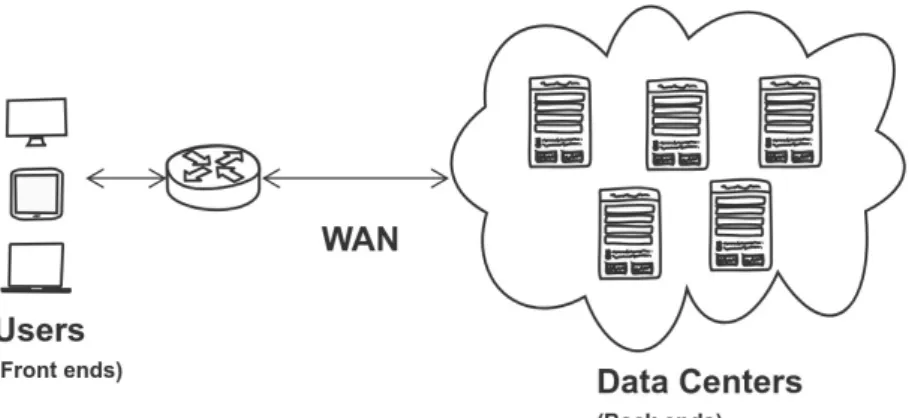
Figure 2.1 presents a general architecture of cloud computing. Cloud computing is based on a centralized architecture and is composed of many elements (servers,
Figure 2.1 – Cloud computing architecture.
switches, firewalls etc.). They are loosely coupled with each other and with the Internet. The architecture has two main parts [178]:
— Front-end: The front-end refers to the client part of services or applications de-ployed in the cloud platform. It consists of application interfaces such as com-mand lines or Graphical User Interfaces (GUI) that are required to access the cloud computing platforms. The front-end part connects to the cloud services through the Internet.
— Back-end: The back-end parts are mainly composed of resources i.e. compute, storage, network as well as software. They are deployed in a handful of data-centers which are connected to each other and to the rest of the Internet with ultra high-speed backbone networks [67]. Some of the popular cloud service providers are Amazon Web Services [84], Google cloud engine [106], and Mi-crosoft Azure [110].
2.1.2
Limitations of cloud computing
The combination of flexibility, scalibility and manageable cost of cloud infrastruc-tures dictated the immense popularity of this new computing paradigm. However, cloud platforms also exhibit limitations. Cloud computing platforms are consist of a handful of powerful datacenters which are connected with high speed networks. However, the small number of datacenters implies that they are deployed very far away from end-users. Users therefore usually use Wide-Area Networks (WAN) to access the services
2.2 Approaches to address cloud computing limitations
deployed in a cloud platform. This architecture leads to important issues which limit the performance of some applications:
a) Latency-sensitive applications such as augmented-reality games require a max-imum end-to-end latency in the order of 20 ms (including network and processing de-lays) [44]. However, the latencies between an end user and their closest data cen-ter come in the range of 20-40 ms (in wired networks) and 40-150 ms (in 4G mobile networks) [1, 30]. Such network delays make it impossible to run the server side of latency-sensitive applications in cloud datacenters [38].
b) A growing number of IoT devices produce large volume of sensor data every day [42]. The server side of IoT data analysis applications is usually deployed in a cloud data center in order to process and analyze the collected data. However, sending such enormous amounts of data to the cloud over long-distance WAN consumes large amount of unnecessary resources and energy [15].
2.2
Approaches to address cloud computing
limita-tions
A number of computing paradigms have been proposed in recent years to address the limitations of cloud computing [136]. For examples, Edge Computing enables com-putational capacity at the edge of the network through small data centers that are placed close to end-users (within 1 or 2 hops away from the users) [111]. However, due to the low processing capacity of small datacenters deployed in Edge computing, the total end-to-end latency (including network and processing delay) may end up being actually greater than using simple cloud computing [171]. A closely related paradigm is Mobile-Edge Computing which focuses on delivering cloud services with minimum latency by deploying computing resources in mobile phone base stations [64]. How-ever, mobile edge computing mainly serves applications which are accessible from mobile clients using cellular network therefore, typical applications are limited to use cases such as content delivery network [66, 172], computational offloading [39], health monitoring [37] etc.
Fog computing was then introduced with the aim of addressing the limitations of both cloud and edge computing. It aims to extend cloud computing datacenters re-sources by bringing additional compute, storage and networking rere-sources in the close
proximity of its end users [34, 53]. By deploying the server part of applications between the cloud and its end user, fog computing promises to enhance performance of applica-tions that need extremely low latency or that process data locally where it is produced, while retaining large amounts of resources in the cloud for non-critical parts.
2.2.1
Fog computing definitions
Defining fog computing precisely is still an ongoing discussion topic, and many slightly different definitions have been proposed. They however all share a common characteristic: resources are available between the cloud and its end users in order to minimize the end-to-end latency of the applications. We present these proposed definitions and highlight the particularity in each individual definition:
1. In 2012, CISCO proposed the first concept of fog computing [32, 85]. IoT deploy-ment requires mobility support, location awareness, geo-distribution and low la-tency. The authors argue that fog computing can provide all these requirements by extending datacenters with additional resources located close to end users. “Fog computing is a highly virtualized platform that provides compute, storage, and networking services between IoT devices and traditional cloud computing data centers, typically, but not exclusively located at the edge of network.” 2. In 2014, Vaquero et al defined Fog computing as a computing paradigm that
can provide network functionality, service management, with a particular focus on privacy [188]:
“A large amount of heterogeneous, ubiquitous, and decentralized devices that can cooperate to form a network for storage and processing without third-party intervention.”
3. In 2017, the OpenFog Consortium was established to standardize Fog architec-ture and protocols to support cloud computing services in IoT devices and edge ecosystem [149]. OpenFog emphases the “horizontal” aspect which means fog infrastructure consist of a large number of fog nodes that are distributed across a large geographical location. The same standard was later adopted by IEEE [14]. “A horizontal, system-level architecture that distributes computing, storage, con-trol and networking functions closer to the users along a cloud-to-thing contin-uum.”
2.2 Approaches to address cloud computing limitations
Figure 2.2 – Distributed fog computing architecture.
Since the OpenFog Consortium was established to standardize fog protocols and their definition was accepted by IEEE, we expect this definition will be used in future fog computing research. Therefore, we adopt the same definition given by OpenFog Consortium in this work.
2.2.2
Fog computing architecture
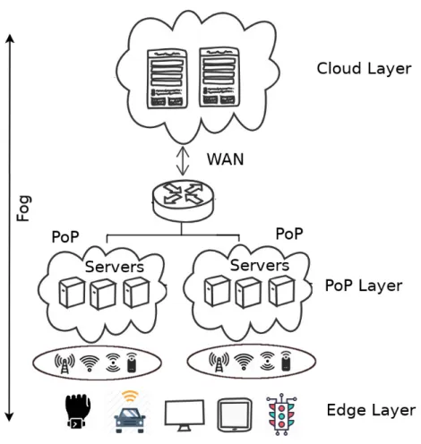
Figure 2.2 presents a distributed fog computing architecture. The architecture con-sists of 3 layers.
1. Edge Layer: The bottom layer is the edge layer which is closest to the end users
and their physical environment. It mainly consists of IoT sensors, mobile phones, smart vehicles, wearable devices, street cameras etc. The devices belonging to this layer collect data from their surroundings and send them to the upper layers for further processing and storage. Depending on the applications, they
may also receive results back from the fog that allows them to actuate their environments. The edge devices usually use available access network (such as cellular network, WiFi and LoRa) to connect to the upper layers.
2. PoP Layer: The intermediate layer between end devices and the cloud is the
PoP layer. A fog infrastructure aims to bring compute, storage and networking resources in the immediate proximity of its end users. It is therefore composed of widely distributed small groups of servers also known as Points of Presence (PoP) placed in strategic locations such as shopping malls, bus stations, streets, stadiums etc. across a potentially large geographical area. Each PoP contains a small number of devices such as single-board computers [200], drones [141], vehicles [208] etc. with limited compute and storage capacity. These devices can be either static or mobile [137, 185]. The servers which belong to the same PoP are collocated with each other which implies that they may easily be con-nected to each other using a fast local-area network. The devices in a PoP layer are equipped with IP networking and thus able to communicate with rest of the Internet and the cloud generally using commodity networks. Fog applications that need compute, storage and network resources close to the end users are deployed in this layer.
3. Cloud layer: The top most layer is the cloud layer. It mainly consists of powerful
datacenters connected to each other and to the rest of the Internet with high-speed networks. It contains powerful computing and storage capacity to support applications which need extensive computational analysis and back end stor-age, can support being deployed far from the end users.
As the architecture of fog computing is different from cloud computing, we present a comparison of important characteristics of the two computing paradigms in Table 2.1.
2.2.3
Application deployment frameworks in fog computing
Many research efforts have been made for building a highly scalable, flexible, ef-ficient fog application deployment framework that can support cloud-like workloads. Bonomi et al. suggested that fog devices should be configured either as virtualized re-sources as in traditional cloud, or offered as bare metal servers [31]. GigaSight uses virtual machine (VM)-based cloudlets to deploy privacy-aware video analytic applica-tions in three-tier architecture [167]. VM-based virtualization is considered well suited
2.2 Approaches to address cloud computing limitations
Table 2.1 – Different characteristics of fog computing and cloud computing.
Characteristics Fog computing Cloud computing
Latency from end user
Low High
to the closest server
Distance from users Close Far
Architecture Distributed Centralized
Processing capacity Moderate High
Access networks LAN, WiFi, Cellular WAN
Storage capacity Moderate Large
Application types Latency sensitive, IoT analytic General applications
Table 2.2 – Fog application deployment frameworks
Reference Platform Application type Fog node Year
Mobile Fog [79] Not specified IoT Not specified 2013
Satyanarayanan et al [167] VM Analytic Clusters 2015
LEONORE [190] Docker IoT Clusters 2015
Claus [153, 154] Docker General RPI 2015
Foglets [169] Docker General Clusters 2016
Geelytics [40] Not specified Analytic RPI 2016
MEC-conpaas [123] LXC General RPI 2017
Foggy [166, 205] Docker IoT RPI 2017
Bellavista et al [24] Docker IoT RPI 2017
Fogernetes [202] Docker General RPI 2018
in cloudlet environments [168] but it performs poorly in resource-constraint fog devices such as routers, gateways and single-board machines that have significantly low mem-ory, bandwidth and processing capacity [78].
Another way to virtualize fog nodes is using containers [80]. Containers, and particularly Docker containers have important advantages over VMs in fog environ-ments: they are lightweight, portable and easy to deploy and orchestrate in resource-constrained fog nodes. A number of IoT-based application deployment frameworks that rely on Docker containers has been proposed for application deployment in resource-constrained IoT gateways [27, 61, 166, 190, 202]. Kempen et al showed that single-board machines have the potential to run real edge cloud applications [23, 123]. Even extremely resource-constrained devices such as Raspberry PIs may be successfully used to build IoT cloud gateways [24]. With proper configuration, these devices can make up scalable fog platforms with minimal overhead.
Table 2.2 presents a comparison of the different proposed fog application deploy-ment frameworks. We observe that the majority of the frameworks, and in particular the most recent ones, are using Docker containers [91] or Kubernetes [19] for application deployment in single-board machines such as Raspberry Pis. This shows the potential of such devices as fog nodes in the near future.
2.3
Docker
Containers are self-contained software packages that encapsulate everything as a software needs to run: executable binaries, libraries, dependencies, settings etc. They are different from software programs mainly because containers are isolated from other software running in the same host machine and underlying operating system [9, 41, 153]. There are different containerization tools available such as Docker [91], LXC [108], OpenVZ [189], and rtk [119]. Among them Docker is certainly the most pop-ular [140]. Docker is portable, operable, lightweight, and its container images are easily shareable [11]. Popular container orchestration tools such as Docker swarm [102], Ku-bernetes [19], Mesos [109] heavily rely on Docker to create, deploy, and manage the container life cycle [65]. Docker is implemented in Go language [18] and its source code of the project is freely available online [89, 99].
Figure 2.3 shows a host running a set of Docker containers on top of the host oper-ating system. Docker uses special Linux kernel features such as namespace [187] and cgroups [186] to virtualize hardware resources such as compute, network and storage. In the earlier versions of Docker, this was done with the help of LXC containers [108]. Since Docker version 0.9, the libcontainer library [97] is used to integrate low-level Kernel namespace [187] and cgroups [186] features directly [90, 180]. Applications running inside Docker containers are packaged in the form of images which contain a part of the container file system with the required libraries, executables, configuration files etc [87]. All the containers running in the same host share the underlying Linux kernel of the host, which makes the size of the Docker images much smaller compared to virtual machine images [170].
2.3 Docker
Figure 2.3 – Multiple Docker containers running in a same host machine (adapted from [91]).
Figure 2.4 – Docker architecture (adapted from [93]).
2.3.1
Docker architecture
Figure 2.4 depicts the Docker architecture. It is composed of three main compo-nents: the Docker client, the Docker server and the Docker registry. The architecture utilizes a client-server model and a remote API to create and manage Docker contain-ers [93]. The Docker client and daemon may be deployed on the same host. Alterna-tively the Docker client can connect to Docker daemon running in a remote machine. The Docker client and the daemon communicate using a REST API, or over UNIX sockets or a network interface [93].
— Docker server: The Docker server (also called the Docker daemon) is in charge of the main functionalities of Docker such as creating containers, images, net-works, and volumes.
— Docker client: The Docker client allows one to interact with Docker servers. The
command line is the primary way to interact with Docker server. Upon receiving an instruction, the client sends the request to the selected Docker server us-ing the communication interface. For example, the followus-ing command instructs Docker to download, setup and start a containerized web server.
docker run nginx:latest A full list of Docker client commands is provided in [104].
— Docker registry: A Docker registry server is a repository which stores Docker
images [94]. Docker registries can be of two types: public or and private. A public registry is deployed in a secure environment and publicly accessible to upload or download images. For instance, Docker Hub is the most popular public registry. It hosts nearly 2 millions images and is still growing [56]. On the other hand, a private registry allows only authorized users to upload or download images.
2.3.2
Docker images
Docker images are consist of multiple layers stacked upon one another: every layer may add, remove, or overwrite files present in the layers below itself. This enables developers to build new images very easily by specializing pre-existing images.
The same layering strategy is also used to store file system updates performed by the applications after a container has started: upon every container deployment, Docker creates an additional writable top-level layer which stores all file system up-dates. The container’s image layers themselves remain read-only.
A Docker image can be build from a Dockerfile. A Dockerfile is a human-readable file which contains list of instructions to build an image [88]. Docker provides a standard docker build command which reads the supplied Dockerfile and creates image layers sequentially starting from the first instruction [81].
Figure 2.5 shows a typical example of a Dockerfile for building a Python-based Docker image. This Dockerfile contains four instructions, and which creates a new layer in the image. The first instruction is the FROM statement which indicates the image is built from a pre-built ubuntu:15.04 image. The COPY command adds files from the
2.3 Docker
FROM ubuntu:15.04
COPY . /app
RUN make /app
CMD python /app/app.py
Figure 2.5 – Dockerfile for creating “stream:1.0” Docker image.
Figure 2.6 – Structure of “stream:1.0” Docker image.
current working directory to the container file system. The third RUN instruction builds the application using the make command. Finally, the last instruction specifies which command to run when a container of the image is deployed. Figure 2.6 shows the resulting image built from the above Dockerfile. A full list of instructions to build a Docker image is given here [96].
Docker encourages layer reusability so it is frequent that different images would share the same bottom-level layers and differ only by their top-level ones [76]. To im-plement layer reusability Docker applies Copy-On-Write(CoW) strategy while creating the image layers [197]. If a file or directory already exists in a lower layer of an image and another layer needs to read the file or the directory, then Docker simply reads from the lower layer. However, when the file or the directory is modified for the first time, Docker copies the modified file or directory in the top layer.
Docker storage drivers
Docker stores each image layer separately in the local file system. It then exposes a unified view of a set of layers to the running containers, thanks to a storage driver whose main purpose is to handle the different layers (i.e., mutable and immutable
lay-ers) in the container image [181]. A storage driver also handles details about the way different layers interact with each other. Multiple storage drivers are available, includ-ing AUFS [193], Overlay and Overlay2 [199], Devicemapper [198], Slacker [76] and btrfs [194].
— AUFS: AUFS is a union filesystem [201]. The main principle of a union file
sys-tem is that it layers multiple directories or branches on a single Linux host and presents them as unified single directory. The branches in AUFS drivers are used to represent different Docker image layers. AUFS storage driver unifies all the layers of the image and exposes them as a single file system. AUFS also implements the Copy-on-Write (CoW) strategy in order to maximize storage ef-ficiency (i.e., re-usability of image layers).
— OverlayFS: OverlayFS is a union file system similar to AUFS, but faster and
based on a simpler implementation [101]. It layers multiple directories on a single Linux host and presents them as a single directory. OverlayFS refers to the lower read-only directories as lowerdir and the upper read-write directory as upperdir. The unified view is exposed through its own directory called merged which is the containers’ mount point.
— Devicemapper: Unlike the previous drivers, Devicemapper works at the block
level rather than the file system level. It relies on Linux’s device-mapper subsys-tem to create a set of thin-provisioned block devices. Firstly, Docker creates a pool, which typically sits on top of two physical devices— one for user data and one for device-mapper metadata (e.g., block mappings). Secondly, when Docker creates a container, the Devicemapper driver allocates an individual volume for the container from the pool. Devicemapper implements CoW by creating new volumes from writable snapshots of previously created volumes.
However, Docker containers operate on file systems rather than a provided raw block device. Therefore, a third step is to format the volumes with a configurable file system (either Ext4 or XFS). The big advantage of Devicemapper over the union file systems (AUFS or Overlay2) is that it can perform CoW at a block level granularity (512kB by default) rather than a single file as in union file systems. On the other hand, Devicemapper is completely file system-oblivious and therefore cannot benefit from using any file system information during snapshot creation.
— Btrfs: Btrfs [194] is a CoW file system based on B-tree structure [165].
![Figure 2.4 – Docker architecture (adapted from [93]).](https://thumb-eu.123doks.com/thumbv2/123doknet/14590599.730090/40.892.193.741.497.777/figure-docker-architecture-adapted-from.webp)
![Figure 2.8 – Multiple container images sharing the same underlying layers (adapted from [87]).](https://thumb-eu.123doks.com/thumbv2/123doknet/14590599.730090/46.892.195.729.176.497/figure-multiple-container-images-sharing-underlying-layers-adapted.webp)