HAL Id: tel-01750224
https://tel.archives-ouvertes.fr/tel-01750224v2
Submitted on 25 Feb 2014HAL is a multi-disciplinary open access
archive for the deposit and dissemination of sci-entific research documents, whether they are pub-lished or not. The documents may come from teaching and research institutions in France or abroad, or from public or private research centers.
L’archive ouverte pluridisciplinaire HAL, est destinée au dépôt et à la diffusion de documents scientifiques de niveau recherche, publiés ou non, émanant des établissements d’enseignement et de recherche français ou étrangers, des laboratoires publics ou privés.
A Simulation Framework for the Validation of Event-B
Specifications
Faqing Yang
To cite this version:
Faqing Yang. A Simulation Framework for the Validation of Event-B Specifications. Formal Languages and Automata Theory [cs.FL]. Université de Lorraine, 2013. English. �NNT : 2013LORR0158�. �tel-01750224v2�
AVERTISSEMENT
Ce document est le fruit d'un long travail approuvé par le jury de
soutenance et mis à disposition de l'ensemble de la
communauté universitaire élargie.
Il est soumis à la propriété intellectuelle de l'auteur. Ceci
implique une obligation de citation et de référencement lors de
l’utilisation de ce document.
D'autre part, toute contrefaçon, plagiat, reproduction illicite
encourt une poursuite pénale.
Contact : [email protected]
LIENS
Code de la Propriété Intellectuelle. articles L 122. 4
Code de la Propriété Intellectuelle. articles L 335.2- L 335.10
http://www.cfcopies.com/V2/leg/leg_droi.php
École Doctorale IAEM Lorraine DFD en informatique
———————————————————————————————————
Un environnement de simulation pour la
validation de spécifications B événementiel
THÈSE
présentée et soutenue publiquement le 29 Novembre 2013 pour l’obtention du
Doctorat de l’Université de Lorraine
(Spécialité : informatique)
par
Faqing Y
ANGComposition du jury Rapporteurs :
Michael LEUSCHEL Professeur, Université de Düsseldorf, Allemagne
Catherine DUBOIS Professeur, ENSIIE, Evry
Examinateurs :
Pascale LEGALL Professeur, Ecole Centrale, Paris
Stephan MERZ Directeur de recherche, INRIA, Nancy
Directeurs de thèse :
Jeanine SOUQUIÈRES Professeur, Université de Lorraine, Nancy, LORIA
Jean-Pierre JACQUOT Maître de conférences, Université de Lorraine,
Nancy, LORIA
———————————————————————————————————
UMR 7503
Acknowledgments
———————————————————————————————————
Foremost, I would like to express my sincere gratitude to my advisor Prof. Jeanine Souquières and my co-advisor Dr. Jean-Pierre Jacquot for the continuous support during my Ph.D. study and research, for their patience, motivation, enthusiasm, and immense knowledge. Without their guidance, I cannot imagine to successfully achieve my research goals. I would also like to thank their helps in my life, especially in a foreign country. I would always remember them as the best advisors and the mentors for the lifetime.
Furthermore, I would like to thank the rest of my thesis committee : Prof. Michael Leuschel, Prof. Catherine Dubois, Prof. Pascale Le Gall, and Dr. Stephan Merz, for their participation, insightful comments, and constructive criticism.
In addition, I am indebted to the colleagues from MAIA and TRIO teams at LORIA with special thanks to Dr. Alexis Scheuer for his development of the 2D platooning mathematical model.
I would like to especially dedicate this thesis to my family, for their love, support, patience, and understanding. They allowed me to spend most of the time on this thesis. Last, but certainly not least, I am thankful to my friends, for all the moral encouragement and support.
Contents
1 Introduction 1 1.1 Motivation. . . 1 1.1.1 Research Context . . . 1 1.1.2 Scientific Problem . . . 2 1.1.3 Technical Problems . . . 2 1.1.4 Objectives. . . 3 1.2 Contributions . . . 3 1.3 Case Studies. . . 4 1.4 Publications . . . 4 1.5 Thesis Outline. . . 62 State of the Art 7 2.1 Introduction . . . 7
2.2 Development Process . . . 8
2.2.1 Construction Activities . . . 9
2.2.2 Verification and Validation Activities . . . 10
2.2.3 Other Activities . . . 11
2.2.4 Some Process Models . . . 11
2.3 Formal Methods. . . 13 2.3.1 Formal Specification . . . 13 2.3.2 Formal Verification . . . 14 2.3.3 Code Generation . . . 14 2.4 B Method . . . 14 2.4.1 Overview . . . 14 2.4.2 Presentation of Event-B . . . 15 2.4.3 Rodin Platform . . . 18
2.5 Animation of Event-B Models . . . 20
2.5.1 Animation Difficulties . . . 20
2.5.2 Event-B Animators . . . 20
2.5.3 Multi-level Animation of Refinement . . . 22
2.6 Platooning Models . . . 23 2.6.1 Platooning Problem. . . 23 2.6.2 1D Platooning Models . . . 24 2.6.3 2D Platooning Model. . . 25 2.7 Summary . . . 27 i
ii CONTENTS
I Assessment of Event-B Usability 29
3 Analysis of the 1D Platooning Model 31
3.1 Introduction . . . 31 3.2 Proofs . . . 32 3.2.1 Interactive Proof . . . 32 3.2.2 False Statement . . . 33 3.2.3 Unprovable Goal . . . 34 3.3 Non-Collision Property . . . 36 3.3.1 Machine platoon0. . . 36 3.3.2 Machine platoon1. . . 37 3.3.3 Machine platoon2. . . 37
3.3.4 Machine platoon3 and platoon4 . . . 38
3.4 Summary . . . 38
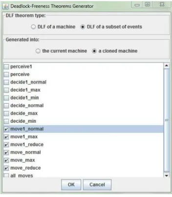
4 Automatic Generation of DLF Theorems 39 4.1 Introduction . . . 39
4.2 Deadlock-Freeness Rule . . . 40
4.2.1 Deadlock-Freeness of Complete Model . . . 40
4.2.2 Deadlock-Freeness of a Subset of Events . . . 40
4.3 Exigence of a Tool . . . 41
4.4 Implementation Issue . . . 42
4.5 Usage . . . 42
4.6 Summary . . . 43
5 Scaling Up with Event-B 45 5.1 Introduction . . . 45
5.2 Model Structure . . . 46
5.2.1 Decomposition of Events . . . 46
5.2.2 Increase in Complexity . . . 48
5.3 Physical and Mathematical Equations . . . 48
5.3.1 1D Equation Adaptation . . . 48 5.3.2 2D Equation Adaptation . . . 49 5.4 Temporal Properties. . . 50 5.5 Adaptation of Tools . . . 51 5.5.1 Edition . . . 52 5.5.2 Verification . . . 52 5.5.3 Validation . . . 52 5.6 Summary . . . 53
II JavaScript Simulation Framework for Event-B 55 6 JeB Design 57 6.1 Introduction . . . 57
6.2 Requirements for a Simulation Generator . . . 58
CONTENTS iii
6.4 Implementation Choices . . . 61
6.5 Translation Strategies . . . 62
6.5.1 Annotations vs. Set Library . . . 62
6.5.2 Interfaces for User Hand-coded Functions . . . 63
6.5.3 Invariant, Witness and Variant . . . 63
6.5.4 Quantified Formulas . . . 64 6.6 Summary . . . 64 7 JeB Implementation 65 7.1 Introduction . . . 66 7.2 Namespace . . . 66 7.3 Translation of Contexts . . . 67
7.3.1 Sets and Constants . . . 68
7.3.2 Axioms . . . 68 7.3.3 Constant Checker . . . 68 7.4 Translation of Machines . . . 68 7.4.1 Variables . . . 69 7.4.2 Invariants . . . 70 7.4.3 Events. . . 70 7.4.4 Event Parameters . . . 71 7.4.5 Event Guards . . . 72 7.4.6 Event Actions. . . 73 7.4.7 User Interface. . . 74 7.5 Translation of Formulas . . . 75 7.5.1 Predicates . . . 75 7.5.2 Expressions . . . 76 7.5.3 Assignments . . . 78
7.6 Interpretation of Translated Formulas . . . 79
7.7 Simulation Control . . . 79
7.7.1 Simulation Scheduler . . . 79
7.7.2 Parameters of a Simulation . . . 80
7.7.3 Scenario Controller . . . 80
7.7.4 Animator . . . 80
7.8 Event-B Project Diagram . . . 81
7.9 Summary . . . 81
8 JeB Utilization and Analysis of Simulations 83 8.1 Introduction . . . 83
8.2 Simulation of the 1D Platooning . . . 84
8.2.1 Minimal Simulation . . . 84
8.2.2 Graphic Display . . . 86
8.2.3 Simulation of the Refinements . . . 86
8.3 Simulation of the 2D Platooning . . . 86
8.3.1 Carrier Sets . . . 87
8.3.2 Functions Defined by Properties . . . 88
iv CONTENTS
8.4 Observations on JeB Usage . . . 89
8.4.1 Simulation Cost. . . 89
8.4.2 1D Platooning Model. . . 89
8.4.3 2D Platooning Model. . . 90
8.4.4 Transport-domain Model . . . 91
8.4.5 MIDAS Model . . . 91
8.4.6 Comparison between Existing Animators . . . 92
8.5 Analysis from a Validation Point of View . . . 94
8.5.1 Validation of Axioms . . . 94 8.5.2 Validation of Properties. . . 95 8.6 Summary . . . 96 9 Correctness of Simulations 97 9.1 Introduction . . . 97 9.2 Consistent Behavior . . . 98
9.2.1 Semantics of an Event-B Machine . . . 98
9.2.2 Operational Interpretation of an Event-B Machine . . . 99
9.2.3 Execution of Simulators . . . 100
9.2.4 Correctness of Simulation . . . 101
9.2.5 Proof Obligations . . . 102
9.3 Discussion about the Hypotheses . . . 104
9.3.1 Hypothesis 1 . . . 104
9.3.2 Hypothesis 2 . . . 105
9.3.3 Hypothesis 3 . . . 105
9.4 Summary . . . 105
10 Conclusion and Future Work 107 10.1 Conclusion . . . 107
10.2 Future Work . . . 108
10.2.1 Technique . . . 108
10.2.2 Refinement Process for Event-B . . . 108
10.2.3 Methodology . . . 110
Appendices 113
Appendix A Présentation de la thèse en français 113
Appendix B Translation of Event-B Formulas 125
Appendix C JavaScript Library for Event-B 149
Appendix D 1D Platooning Model in Event-B 183
Appendix E 2D Platooning Model in Event-B 199
List of Figures
2.1 Main development activities . . . 9
2.2 1D platooning model . . . 24
2.3 2D platooning model . . . 26
3.1 The DLF theorem for the machine platoon2 . . . 35
3.2 The unprovable goals in the machine platoon2 . . . 36
4.1 Generator of DLF theorems. . . 43
5.1 The structure of platooning models . . . 47
6.1 JeB simulation framework . . . 60
7.1 Constant checker . . . 69
7.2 A machine user interface . . . 74
7.3 An Event-B project diagram . . . 81
8.1 The definition of Point in Event-B . . . 87
10.1 A step of refinement for Event-B . . . 109
10.2 An extended V-Model. . . 111
A.1 L’architecture de JeB . . . 119
List of Tables
4.1 DLF theorem size . . . 41
4.2 Deadlock-Freeness in the reviewed 1D platooning model . . . 43
5.1 Decomposition of the move event in the 1D model . . . 47
5.2 Decomposition of the move event in the 2D model . . . 47
5.3 Increase in complexity . . . 48
6.1 Requirements for a simulation generator . . . 59
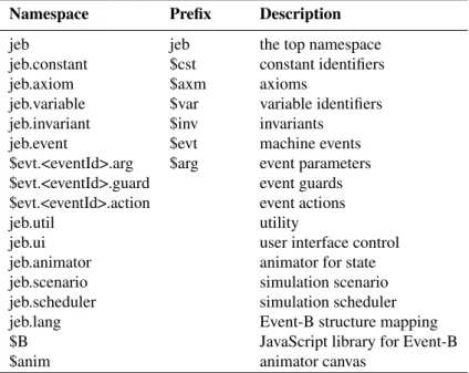
7.1 Namespaces used in the simulator code . . . 67
7.2 Structural mapping of a context . . . 67
7.3 Structural mapping of a machine . . . 69
7.4 Structural mapping of an event . . . 70
8.1 Activities for the 1D platooning simulations . . . 87
8.2 Simulation cost . . . 89
8.3 Technical comparison between the existing animators . . . 92
8.4 The usage of four animators on our case studies . . . 94
9.1 Symbols and notations . . . 98
Chapter 1
Introduction
Contents 1.1 Motivation . . . 1 1.1.1 Research Context . . . 1 1.1.2 Scientific Problem . . . 2 1.1.3 Technical Problems. . . 2 1.1.4 Objectives. . . 3 1.2 Contributions . . . 3 1.3 Case Studies . . . 4 1.4 Publications . . . 4 1.5 Thesis Outline . . . 61.1 Motivation
1.1.1 Research ContextThe classical approaches of developing systems are conducted through activities realized by humans. Unfortunately, humans often make mistakes and mistakes are the most common cause of potential safety-threatening situations. For instance, the first test flight of the Ariane 5 rocket1failed on 4 June 1996, because of a malfunction in the control software. A data conversion from a 64-bit floating point value to a 16-bit signed integer value was left unchecked by engineers; it produced an overflow which led to the destruction of the rocket.
The quality of systems can be improved by reducing human mistakes during the devel-opment process, e.g., by using formal methods for the whole system or some critical subsystems. Formal methods use mathematical logic to abstractly represent systems, to prove that the formal specifications are consistent with the requirements, to prove that the implementations meet the specification, and to generate code from the specifications.
1. http://en.wikipedia.org/wiki/Ariane_5
2 CHAPTER 1. INTRODUCTION
In this thesis, a system is said to be correct if it satisfies two conditions:
– Verified: the system must be internally consistent and it must meet the initial speci-fication, i.e., we are building it right. Verification activities are usually an internal process executed by the developers.
– Validated: the system must fulfill the intended purpose of its users, i.e., we are building the right thing. Validation activities require processes which involve people outside developers (stakeholders).
Using formal methods, getting a verified specification is reasonably easy. However, a ver-ified specification does not automatically result in a validated specification. Verification and validation are independent procedures. They should be used together to assure the correctness of a formal specification. Often, the verification activities are made through mathematical proofs and require significant resources (time, money and experience). This makes formal methods more adapted to the development of safety-critical systems where the cost of faults is very high. For instance, in the railway domain or in the aerospace domain, undetected errors may cause the loss of lives.
This thesis aims at the specification, verification and validation of safety-critical systems with formal methods, in particular, with Event-B. Our research work started from analyzing an existing Event-B specification which formalizes the longitudinal control by a platooning algorithm. The safety property which must hold in the platooning model is the absence of collisions between vehicles. Then we extended this formal specification into two dimensions by adding the lateral control.
1.1.2 Scientific Problem
The most important scientific issue uncovered by case studies used in our research work was:
The mathematical proof of a formal specification is not enough to ensure its correctness: verification does not entail validation.
Proof-based and refinement-based development techniques guarantee that a development is internally consistent, in the formal sense. In particular, those techniques guarantee that all models written during the development meet the initial formal specification. However, non-functional requirements are often very hard to express within standard logics; many requirements are even outside such mathematical frameworks. Hence, they are not in the initial specification. Furthermore, obtaining clear and complete requirements at the early stage of the development is known to be a near-impossible task. Therefore the initial requirements document may be incomplete, ambiguous, inconsistent. As a result, the developers will have to “supply” missing requirements in order to take the necessary decisions during their work. So, the validation activities should be performed on the formal models as early as possible after they have been verified.
1.1.3 Technical Problems
1.2. CONTRIBUTIONS 3
– the absence of practical tools to support validation activities,
– the lack of a guideline to integrate formal reasoning and semi-formal reasoning into a development process.
1.1.4 Objectives
Our work has focused on specific objectives related to the extension of the Event-B usability:
1. The most important objective is about a framework which can simulate the Event-B model for its validation. This framework allows us to guarantee the semantic correctness of simulations. This framework is a complement to existing proving and animation tools that allows to associate validation activities with verifications activities along the chain of refinements.
2. A second objective is to help the verification for the absence of deadlocks in Event-B models.
3. The last objective, more methodological, is to think and enlarge the core notation of refinement used in Event-B. The state-of-the-art refinement emphasizes the verification activities. We complement it with other activities, such as requirements management, adaptation of the mathematical model, checking temporal properties and validation by animation or simulation.
1.2 Contributions
In this thesis, we aim at defining two important contributions. Contribution I: assessment of Event-B usability
The start point of our research work is to assess the Event-B usability:
– a critical analysis of the original 1D platooning specification and the explanation of some anomalies in the behaviors,
– a Rodin plug-in (about 500 lines in Java) to automatically generate deadlock-freeness theorems,
– an assessment of the scalability of Event-B from different aspects (mathematics, structure, temporal properties and tools).
Contribution II: a JavaScript simulation framework for Event-B
Our key contribution is a simulation framework for Event-B, based on JavaScript. This framework generates simulators from Event-B models and provides a lightweight graphic execution environment. Simulators can be used to validate Event-B models at each refinement step. They help final users, domain experts and developers to better understand the mathematical models and the specifications.
4 CHAPTER 1. INTRODUCTION
– an integrated simulation environment for Event-B models, composed of two main elements:
– a translator (about 2800 lines in Java): a Rodin plug-in which automatically gener-ates simulators from Event-B models, and
– a runtime environment and most notably a JavaScript library (about 2700 lines in JavaScript) which supports all Event-B mathematical notations,
– a semantics for the correctness of simulations based on the generation of proof obliga-tions.
1.3 Case Studies
We used four case studies in our research work. These case studies allow us to experiment different strategies of translating Event-B models, implementing the simulator and parameterizing the simulations. At present, all refinements of these models can be simulated by our tool.
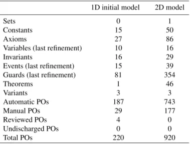
1D Platooning Model This model [Lanoix 2008] was developed to verify a platooning algorithm in one dimension with Event-B. It contains 10 components and about 600 lines of Event-B formal texts. It can be animated by the existing Event-B animators with some strategies. Hence, we use it as a reference.
2D Platooning Model This model [Yang 2011] is an extension of the first model in 2 dimensions. It contains 10 components and about 1800 lines of Event-B formal texts. It has an abstract carrier set and some uninterpreted functions which caused the failure to the existing Event-B animators. Hence, we use it as a test bed.
Transport-domain Model This model [Mashkoor 2009a] formalizes the transport domain in Event-B. It contains 23 components and about 1100 lines of Event-B formal texts. It uses many Event-B mathematical notations, e.g., abstract carrier sets, set comprehensions, non-deterministic assignments. We use this model to test the interface of our Event-B library and the symbolic executions.
MIDAS Model This model [Wright 2009b,Wright 2010] uses Event-B to construct instruction set architectures. It contains 104 components and about 21800 lines of Event-B formal texts. It has a complex structure of contexts, and the longest refinement chain from the abstract machine composed of forty machines. We use it to test the scalability of JeB for a large project.
1.4 Publications
1.4. PUBLICATIONS 5
International conferences
[1] Faqing Yang, Jean-Pierre Jacquot and Jeanine Souquières. Proving the Fidelity of Simulations of Event-B Models. In The 15th IEEE International Symposium on High Assurance Systems Engineering (HASE), Miami, USA, forthcoming 2014. [2] Faqing Yang, Jean-Pierre Jacquot and Jeanine Souquières. JeB: Safe Simulation
of Event-B Models in JavaScript. In The 20th Asia-Pacific Software Engineering Conference (APSEC), Bangkok, Thailand, 2013.
[3] Faqing Yang, Jean-Pierre Jacquot and Jeanine Souquières. The Case for Using Simulation to Validate Event-B Specifications. In The 19th Asia-Pacific Software Engineering Conference (APSEC), Hong Kong, China, 2012.
[4] Faqing Yang and Jean-Pierre Jacquot. Scaling Up with Event-B: A Case Study. In Mihaela Bobaru, Klaus Havelund, Gerard Holzmann, and Rajeev Joshi, editors, NASA Formal Methods (NFM), volume 6617 of Lecture Notes in Computer Science, pages 438–452. Springer Berlin / Heidelberg, 2011.
[5] Faqing Yang and Jean-Pierre Jacquot. An Event-B Plug-in for Creating Deadlock-Freeness Theorems. In 14th Brazilian Symposium on Formal Methods (SBMF), São Paulo, Brésil, 2011.
National conferences
[6] Faqing Yang and Jean-Pierre Jacquot. JeB : un environnement de simulation en JavaScript pour B événementiel. In Approches Formelles dans l’Assistance au Développement de Logiciels (AFADL), Nancy, France, 2013.
[7] Faqing Yang, Jean-Pierre Jacquot and Jeanine Souquières. Traduction de B événementiel en C pour la validation par la simulation. In Approches Formelles dans l’Assistance au Développement de Logiciels (AFADL), Grenoble, France, 2012.
[8] Faqing Yang and Jean-Pierre Jacquot. Prouvé ? Et après ? In Approches Formelles dans l’Assistance au Développement de Logiciels (AFADL), Poitiers, France, 2010.
Article abstract for workshops
[9] Faqing Yang and Jean-Pierre Jacquot. Generating Executable Simulations from Event-B Specifications. In Rodin User and Developer Workshop, Fontainebleau, France, 2012.
[10] Faqing Yang and Jean-Pierre Jacquot. An Event-B Plug-in for Creating Deadlock-Freeness Theorems. In Rodin User and Developer Workshop, Fontainebleau, France, 2012.
[11] Atif Mashkoor, Faqing Yang and Jean-Pierre Jacquot. Validation of formal specification: The case for animation. In 3rd Workshop on Security and Reliability (SecDay), Trier, Germany, 2011.
6 CHAPTER 1. INTRODUCTION
1.5 Thesis Outline
This thesis is organized as follows
– Chapter2describes some related work. Part I: Assessment of Event-B Usability
– Chapter3makes a critical analysis of the 1D platooning specification. – Chapter4describes a tool for generating deadlock-freeness theorems. – Chapter5presents the scalability of Event-B from different aspects. Part II: JavaScript Simulation Framework for Event-B
– Chapter6describes the JeB design philosophy.
– Chapter7gives the JeB translator and simulator implementation.
– Chapter8illustrates how to realize a simulation and some analysis from a point of view of the validation.
– Chapter 9 defines the notion of correctness of simulations and defines the proof obligations related to that property.
– Chapter10gives our conclusion and future work. Appendices
– AppendixAshortly sums up this thesis in French.
– AppendixBgives the detail translation rules for Event-B formulas into JavaScript. – AppendixCdefines the JavaScript library API for Event-B formulas.
– AppendixDpresents the original 1D platooning model in Event-B. – AppendixEpresents the 2D platooning model in Event-B.
Chapter 2
State of the Art
Contents
2.1 Introduction . . . 7
2.2 Development Process . . . 8
2.2.1 Construction Activities . . . 9
2.2.2 Verification and Validation Activities . . . 10
2.2.3 Other Activities. . . 11
2.2.4 Some Process Models . . . 11
2.3 Formal Methods . . . 13 2.3.1 Formal Specification . . . 13 2.3.2 Formal Verification . . . 14 2.3.3 Code Generation . . . 14 2.4 B Method . . . 14 2.4.1 Overview . . . 14 2.4.2 Presentation of Event-B . . . 15 2.4.3 Rodin Platform . . . 18
2.5 Animation of Event-B Models . . . 20
2.5.1 Animation Difficulties . . . 20
2.5.2 Event-B Animators . . . 20
2.5.3 Multi-level Animation of Refinement . . . 22
2.6 Platooning Models . . . 23 2.6.1 Platooning Problem. . . 23 2.6.2 1D Platooning Models . . . 24 2.6.3 2D Platooning Model. . . 25 2.7 Summary . . . 27
2.1 Introduction
In this thesis, we consider a software product as an information system. We address the process of developing software based information systems which are composed
8 CHAPTER 2. STATE OF THE ART
not only of software subsystems, but also of hardware subsystems. How to integrate such subsystems and what is the realistic operational environment of a final system are important aspects which should be accounted for at the beginning of a project. The development process is decomposed into a few main activities. The different development methodologies, e.g., linear, iterative, or agile, are defined by different structures and practices of these activities.
Unlike classical development approaches, formal methods use the mathematical logic to rigorously reason about the correctness of a construction. They provide a strong assurance of the absence of bugs in the software. However, they are generally expensive in resources and thus, they are currently reserved for the development of safety-critical systems. Formal methods can be applied at various points during a development process, in particular, at the specification and the verification stages.
Event-B is a formal method for system-level modeling. It is based on the first order logic and set theory. It uses refinements to represent systems at different abstraction levels and uses mathematical proofs to verify the consistency between refinements. In this thesis, we use Event-B to formalize the platooning problem as the ground base for our research.
2.2 Development Process
Computer science and its application quickly evolved in the passed decades. When the first digital computers appeared in the early 1940s, the computer instructions were wired into the machine whose design was not flexible. The computer system architecture then evolved into "hardware" and "software", with the introduction of more and more abstractions to deal with more and more complex computations. Programming languages appeared in the 1950s; this was also a major step to drive the usage of more abstract notations in the software development. The key concept of modularity and information hiding [Parnas 1972] is used to handle the increasing complexity of software systems. In the 1980s, software engineering emphasized the system structure and its management with large complex specifications. In the mid 1990s, the concept of distributed computing gained greater influence as a way to design systems, while the Java programming language [Gosling 2005] was introduced with its own virtual machine; both ideas were another step toward higher abstractions. In 2001, the Agile Manifesto [Beck 2001] introduced the agile software development which is based on iterative and incremental development and encourages rapid and flexible response to change.
The evolution of developing software based systems focused on two aspects: the control of the development process and the control of the software quality. The former resolves the management problems by adopting some development processes, such as the waterfall model or the agile model. The latter resolves the quality problems, such as reliability and security, which can be considerably improved by applying formal methods.
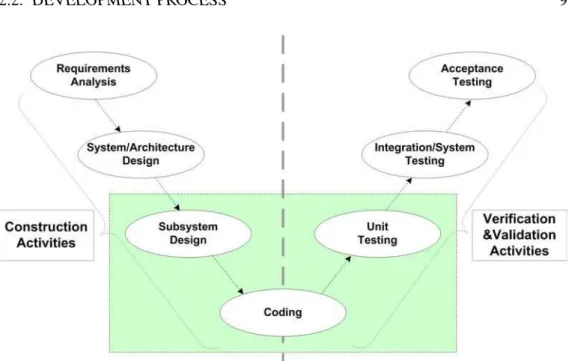
A development process is a set of activities which lead to the production of a soft-ware product. However, there is no ideal approach [Brooks 1987] for different types of software products. Some fundamental activities, like requirements analysis, sys-tems/architecture design, subsystem design, coding and testing, depicted in Figure2.1,
2.2. DEVELOPMENT PROCESS 9
Figure 2.1: Main development activities
are common to all process models. In the following, we give a brief description for each activity by two main catalogs: construction activities, verification and validation activities.
2.2.1 Construction Activities
The aim of construction activities is to produce a system which conforms to the users’ requirements. A high quality requirements document [Balzer 1981] is then a key to suc-cess. The classical approaches construct systems from the initial requirements document which becomes the reference against which the system is verified and validated in later development steps.
Requirements Analysis This activity collects the requirements of the proposed system by analyzing the needs of the user. It establishes what the expected system has to build, but it does not specify how the system will be designed. Usually, the needs are collected into a document, the “User Requirements Specification,” which is the output of this phase.
The user requirements document is used to describe the system properties expected by the user, such as functions, interface, data security, and so on. The plan-driven process models, like the waterfall model, emphasize that the user reviews very carefully this document as it will serve as a guideline for following development activities. The user acceptance testing is carried out according to this document.
10 CHAPTER 2. STATE OF THE ART
System/Architecture Design A system design analyzes and decides the business logic of the proposed system according to the user requirements document. It looks for feasible techniques to implement the user requirements. If some of requirements are not feasible, an alternative solution is proposed to the user and the requirements document is modified accordingly.
The architecture design specifies the architecture of the system and its software part in a high-level abstract formalism. It should consist of a list of subsystems, with precise descriptions of their functionality, their interface and relationships with other subsystems, the dependencies between sub-systems, etc.
Usually a system design document is generated at the end of this activity. It serves as a blueprint for the subsystem design and the coding activities. The integration/system testing is carried out according to this document.
Subsystem Design The subsystem design is a lower-level description of the system. The final system is broken up into smaller subsystems or units. Each of them is described in detail and then can be coded directly.
For each subsystem, a subsystem design document is generated, which contains detailed functional logics, such as database tables, interface details, dependency issues, complete inputs and outputs. The unit testing is carried out according to this document.
Coding This activity results in the executable code for each subsystem. It consists of writing, debugging and testing the source code of a subsystem according to its design document. These codes are often written in one or more programming languages. Some flaws in programs can be more or less easily found by debugging and testing, but certain complex business logics are difficult to be detected in this phase.
2.2.2 Verification and Validation Activities
The verification and validation [Adrion 1982,Andriole 1986] activities are independent procedures. They are used together for checking that (i) a product, service, or system meets its requirements and specifications, and (ii) a product, service, or system meets the intended purpose of the user. These activities are critical elements to achieve a certified software system [Maibaum 2007].
Informally, we express the validation by the question "Are you building the right thing?" and the verification by "Are you building it right?". The IEEE standard [IEEE 2004] give their descriptions as follows:
The verification process provides objective evidence whether the software and its associated products and processes: (i) conform to requirements for all life cycle activities during each life cycle process, (ii) satisfy standards, practices, and conventions during life cycle processes, (iii) successfully
2.2. DEVELOPMENT PROCESS 11
complete each life cycle activity and satisfy all the criteria for initiating succeeding life cycle activities.
The validation process provides evidence whether the software and its associated products and processes (i) satisfy system requirements allocated to software at the end of each life cycle activity, (ii) solve the right problem, (iii) satisfy intended use and user needs.
Unit Testing Unit testing aims at verifying the internal logic of the code by exploring every possible branch of the control flow of a subsystem. This testing is usually white-box while the code is directly checked for errors. Static analysis tools are used to facilitate this process without actually executing programs. Usually, the state space explosion prevents these tests to be exhaustive and induces high costs.
Integration/System Testing After the disjoint subsystems are assembled into a single system, the integration testing looks for faults in the interfaces and in the interaction between the integrated subsystems. This testing is usually conducted in a black-box spirit: the source code is not visible to the tester and not directly checked for errors. Once the integration testing is complete, the system testing will be executed to compare the system specifications against the actual system and to check if the integrated system meets the specified requirements.
Acceptance Testing This activity is used to determine whether a system satisfies the requirements specified in the user requirements document. The customer uses the defined acceptance criteria to determine whether to accept the system or not. Once the acceptance testing is complete and its results approved, the developed system will be deployed and delivered to the customer.
2.2.3 Other Activities
Other activities complement the life cycle of a system, such as the project definition and the maintenance. The project definition finds out the organization’s objectives, the scope of the problem to resolve, other alternative solutions, the cost and benefits, etc. The maintenance occurs once the system is delivered and operational. The purpose of maintenance is to correct faults, to improve performance and to enhance the system functionality, etc. Usually it has the longest period in the system life cycle.
2.2.4 Some Process Models
A process model is an abstraction of a development process. Several models are widely used in the current software engineering practice. Each one has its advantages and disadvantages. The development team should adopt the most appropriate one for a
12 CHAPTER 2. STATE OF THE ART
project, ideally, within the policies of the organization. Sometimes a combination of these models may be more suitable for a large project.
Waterfall Model The waterfall model [Royce 1970] is one of the first published mod-els of the development process. This model divides a development in sequential phases. The developers follow these phases in order: requirements analysis, system design, implementation, integration, testing, deployment and maintenance.
This model discourages revisiting and revising any prior phase once it’s complete. It can be adopted for a project when (1) requirements are very well known, clear and never changed; (2) product definition is stable; (3) the project is short.
V-Model The V-model [Forsberg 1995] is considered as an extension of the waterfall model. The development phases form a typical V shape unlike a linear way in the waterfall model. The V-Model emphasizes the relationships between a phase in the construction and its associated testing phase in the verification and validation. The horizontal axis represents project completeness and the vertical axis represents the abstraction level of the development.
This model greatly emphasizes testing activities, and in particular, the importance of early test planning. It has evolved over time to improve its flexibility and agility for different type of projects.
Spiral Model The spiral model [Boehm 1988] is based on the continuous refinement of the key products realized during requirements definition and analysis, system and software design, and implementation. At each iteration around the cycle, the products are extensions of earlier products. This model emphasizes iterative risk analysis and management. Starting from the center, each turn around the spiral goes through several tasks: 1) determine the objectives; 2) identify and resolve risks; 3) develop and test the product; 4) plan the next iteration.
It is reasonable to use this model in projects where the business goals are unstable but where the architecture must be strong enough to support high load and resist high stress.
Agile Software Development The Agile software development is a philosophy of developing software based on iterative and incremental developments [Larman 2003]. It is not a set of tools or a single methodology. The self-organizing teams and their interactions play an important role in the development process. It emphasizes on rapid iterations, frequent delivery of working software, close collaboration with customers and business experts, quick responses to the requirements change. The face to face communication is considered more effective than written documentation. The working software is considered more useful than presenting documents to clients.
However, agile development is more suitable for small teams. It is often recognized as inefficiency in large organizations and certain types of projects (e.g., mission-critical systems). Large-scale agile software development is still in the field of active research.
2.3. FORMAL METHODS 13
2.3 Formal Methods
Formal methods [Wing 1990,Clarke 1996] are mathematical techniques for specification, design and verification of software based systems. They use mathematical logic to reason rigorously about the software construction in order to obtain a reliable and robust system. They enable a good warranty regarding the lack of "bug" in the software. They ensure that the implementation of a software conforms to its specification. However, the application of formal methods is generally costly resources and is currently reserved for developing safety-critical systems. For example, in railway [Butler 2002] and aerospace [Ait Ameur 2010] systems, undetected errors may cause death.
A safety-critical system is that the failure or malfunction of a system can have dramatic consequences, such as death, serious injury, equipment damage and environmental harm. The failure rate is generally allowed to be less than one life per billion (109) hours of operations in safety-critical systems. The probabilistic risk assessment, failure mode and effects analysis (FMEA) [Stamatis 2003], fault tree analysis are usually used to evaluate risks and failure analysis.
To develop safety-critical systems, the classical approach is to let humans make the development while applying extra care. But humans easily make mistakes, and these mistakes are the most common cause of safety-threatening errors. Some serious disasters were caused only by a little human mistake. For example, the first test flight of the Ariane 5 rocket on 4 June 1996 failed by a mis-checking on a data conversion.
The quality of safety-critical systems can be improved by using formal methods to develop their critical subsystems [Rushby 1993]. Mathematical proofs ensure that the specifications meet the requirements. Sometimes the executable code can be generated from the formal specifications directly. In such cases, unit testing can be removed from the development process: the correction of the construction is guaranteed by mathematical proofs.
There is often some misunderstanding on the role and application of formal methods [Bowen 1995a,Bowen 1995b,Bowen 2006]. These ideas have overemphasized full for-malization of a specification or design. Since a full forfor-malization of a system is a difficult and expensive task, various lightweight formal methods [Jackson 2001,Barner 2005] have been proposed, which emphasize partial specifications and focused applications. Formal methods can be applied at various points through the development process, in particular, at the specification, the verification, and the code generation.
2.3.1 Formal Specification
Formal specifications [Lamsweerde 2000] use mathematical techniques to give a precise and unambiguous description of a system. They use rigorous and effective reasoning tools to describe a system, to analyze its behavior, and to verify interest properties. They help uncover problems and ambiguities in the system requirements. They can be used to guide further development activities.
14 CHAPTER 2. STATE OF THE ART
2.3.2 Formal Verification
Once a formal specification has been developed, the specification should be verified [Bjesse 2005] to prove the correctness of systems. Two main techniques are used to do formal verification: model checking and theorem proving.
Model Checking Model checking is a technique for automatic verification of a given model of a system: whether this model satisfies its specification. It consists of a system-atic and, ideally, exhaustive exploration of the space defined by a mathemsystem-atical model. The specification to be verified is often formulated in terms of temporal logic, such as linear temporal logic or computational tree logic. The advantage of model checking is that it is mostly automatic and easily to product a counter-example; but it often does not scale up well to large systems, especially due to the state explosion problem. Sev-eral approaches are used to combat this problem, such as symbolic execution, abstract interpretation, partial order reduction.
Theorem Proving Theorem proving is a deductive method. Firstly a collection of mathematical proof obligations is generated from a system specification. The correctness of a system is then assured by discharging these proof obligations using either theorem provers or SMT solvers. This approach does not suffer the problem of state space explosion and it can be applied to large systems. This approach may require some experiences and skills to manually discharge plenty of proof obligations, in some cases, which is not an easy task.
2.3.3 Code Generation
A formal specification may be used as a guide for the implementation of the system. Refinement based formal methods, like B Method, support gradually add more details about data structures and algorithms to obtain a deterministic version. This deterministic refinement may be directly translate into source code in a target programming language, like [Bert 2003].
2.4 B Method
B method is successfully deployed in many industry projects. This thesis focus on the extension of Event-B usability.
2.4.1 Overview
B is a formal specification language invented by Jean-Raymond Abrial based on the first order logic and set theory. It allows accurately express system properties and prove these properties in a systematic way. Then we can take into account these properties to guide
2.4. B METHOD 15
further development activities. The correctness of construction is fully controlled by the discharge of many mathematical proof obligations (PO).
The B method is a mature construction approach based on the B Language. It uses refinements, proof obligation and is fully supported by tools. A development in B starts with writing an abstract model that includes all the requirements: the main data processed by the system is described, as well as the fundamental properties of this data.
The B model thus obtained is a specification of what the system should do. Then the B model is transformed by a succession of refinements into a concrete model that can be coded into a language such as C or Ada. Each refinement can be proven, and so, the development leads to a fault-free software. The B method has been successfully applied in several industrial projects, such as [Behm 1999,Gerhart 1994,Patin 2006].
The B method has two versions: classic B [Abrial 1996] and Event-B [Abrial 2010]. Both languages are based on first order logic and set theory.
Classic B is used in the development of computer software elements, it is supported by tools such as Atelier B [Cle 2009b] or B-Toolkit [B-Core(UK) Ltd 1996]. Atelier B is a commercial tool which includes the ability to translate the refinements into a standard programming language.
Event-B is an evolution of Classic B. It uses only an event notation [Abrial 1999] to describe the state transitions; it is supported by the Rodin platform [RODIN 2012]. Compared to Classic B, Event-B has the capacities to model a system.
2.4.2 Presentation of Event-B
Event-B [Abrial 2010] is a formal framework to specify complex systems. It can be analyzed along three axis:
– Description axis: systems are modeled as a state, i.e., a mapping from names to values; they are constrained by an invariant, i.e., a conjunction of predicates on the state, and a collection of events. Events are discrete modifications of the state.
– Semantics axis: it is based on the notion of correctness. A model is correct if it enjoys several demonstrable properties, mainly: well-typedness, existence of actual states and invariant preservation. These properties are expressed as POs that can be automatically generated.
– Development axis: Event-B embed a notion of formal refinement which allows specifiers to use a stepwise development strategy. The correctness of refinements is defined by POs which guarantee that the invariant of the previous machine is preserved by the refinement.
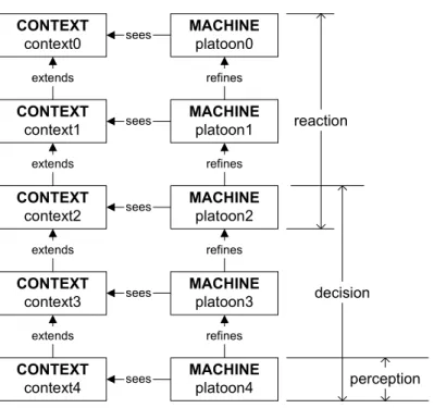
An Event-B model has two kind of components : contexts and machines. Contexts are used to describe the static elements of a system. Machines are used to specify the dynamic behavior of a system. A context may be extended to many other contexts; a context may also extend many other contexts. A machine may be refined to many other machines; but a machine may at most refine one machine in the Rodin platform.
16 CHAPTER 2. STATE OF THE ART
Contexts Contexts describe the static properties of a model. In fact, a given model is parameterized and can be instantiated with associated contexts. A context contains sets, constants, axioms, and theorems. Sets are user-defined types, classified by carrier sets and enumerated sets. Each constant must declare its type in axiom section. The properties of sets and constants are described by axioms. Axioms are considered as hypotheses used in proofs, they are only required be well-defined. So it is possible to introduce a wrong axiom to a model. Axioms can be marked as theorems for derived properties. A theorem must be proved by the axioms written before this theorem; The proved theorems can be used later in proofs just like the other axioms.
Machines Machines describe the dynamic behavior of a model. A machine contains variables, invariants, events, theorems, and variants. Variables constitute the system state, whose values are determined by an initialization event and can be changed by events. Like constants, variables can be any mathematical objects defined in Event-B language, such as integers, sets, relations and functions, etc. Invariants specify the system behavioral properties with variables. They are predicates that should be held for every reachable state. Events are guarded substitutions to change the values of variables. Like axioms, any predicate defined in invariants or event guards can be marked as theorems which should be proved within the machine. A variant is a numeric expression or a finite set to support proofs for event termination.
Event An event represents a transition. It is a guarded substitution. Each event is composed of an arbitrary number of parameters, guards and actions. The guards defined the necessary conditions when an event is enabled to execute. The actions specify how to change the variables’ values. They may be deterministic assignments or non-deterministic assignments. When an enabled event is executed, only the variables specified in the actions are changed their values, the other variables keep their old values.
Events have three kind of forms. Let v be a collections of state variables in a machine, x be a collections of parameters of an event, G(x,v) be the guards of an event, S(x,v) be the actions of an event, the general form for an event is:
ANY x WHERE G(x, v) THEN S(x, v) END
The second form is used when there is no parameters:
WHEN G(v) THEN S(v) END
The last form is used when there is neither guards nor parameters:
BEGIN S(v) END
The initialization of the machine is a special event using the last form.
An intuitive operational interpretation of an Event-B model consists in checking if values can be assigned to the parameters to make the guard true for an event, and then to execute the substitution. More generally, execution is a procedure in four steps: (1) to pick (or compute) and assign values to the parameters, (2) to compute the set of enabled events,
2.4. B METHOD 17
(3) to choose one enabled event, and (4) to pick (or compute) and assign values to the substituted variables.
The validation of a model can then be done by observing the evolution of the state’s values and the sequences of events fired during executions. Technically, assigning values to parameters, choosing an enabled event to fire and determining the substituted values introduce non-determinism in executions.
Refinement The progress towards implementation is made by following a gradual refinement process. A refinement is the transformation of an abstract model into a more concrete and elaborate model. New variables can be introduced in the state, either as addition or as reification of the abstract variables. This introduction is reflected in the substitutions of the events. A WITH clause expresses the link between the parameters of an abstract event, (possibly removed from the refined event) and their concretization. New events may also be introduced. Except when specified as refining an abstract event, new events are assumed to refine the SKIP event. These new events should not prevent forever the old ones from being triggered. A VARIANT can be introduced to ensure this property. It consists of a numeric expression or a finite set which must decrease each time a new event is fired. Proof obligations ensure that the refined model is consistent, i.e., its INVARIANT is preserved, and the VARIANT is decreased by the new events. Furthermore, they ensure that the refinement is correct, i.e., the refined events do not contradict their abstract counterpart.
Semantics The mathematical semantics of Event-B is defined by a set of logical properties of the model, mostly concerned about the possibility to instantiate an actual state and about the preservation of invariants. The syntax of Event-B and the model structure allow tools to automatically generate Proof Obligations (POs). A model is correct,in the B sense, when all POs have been discharged.
The most important POs can be classified as follows: WD (well-definedness), THM (provable theorem), INV (invariant preservation), GRD (guard strengthening), SIM (action simulation), FIS (feasibility), VAR (decreasing of variant).
WD POs ensures that formal predicates, expressions and assignments are indeed well defined. They are mainly a form of type-checking or have special conditions for some particular formulas. Typing in B and Event-B is based on set membership.
THM POs ensures that a theorem declared in a context or a machine is indeed provable. In the Rodin platform, axioms, invariants and guards can be marked as theorems, so they can be proved and used in a proof. The validity of a theorem must be proven from the axioms, invariants or guards declared before this theorem. Theorems are important to simplify some proofs.
FIS and INV POs express the logical consistency of the model. The state modifications are expressed as events, which are substitutions. The guards of an event are predicates that identify a set of pre-states. The actions of an event identify a set of post-states. The Before-After-Predicate (BAP) of an event relates these pre-states and post-states.
18 CHAPTER 2. STATE OF THE ART
INV proof obligations ensure that post state remains within the legal states (where the invariant holds). FIS proof obligations ensure that all the states satisfying the guard are related by the BAP to at least one post-state.
GRD and SIM POs express the consistency of refinements. The former set of POs ensure that a refined event cannot be fired when its counterpart in the abstract model could not. The latter set ensures that all substitutions performed in the abstract model are still performed in the refined model.
VAR POs ensures that an event will terminate to execute after a finite number of times. Events can be marked as: ordinary, convergent and anticipated. An ordinary event may occur arbitrary times without the variant constraint. A convergent event must decrease the variant. An anticipated event must not increase the variant.
In practice, many POs may be trivial; current tools discharge them automatically and silently. Users are presented only with the undischarged POs.
Note that POs cannot guarantee that the behavior of the machine is correct in the user’s sense:POs are only about verification. Validation is required to check that the machine conforms to the users’ actual requirements.
2.4.3 Rodin Platform
The Rodin platform [RODIN 2012] is an Eclipse-based integrated development envi-ronment for Event-B. It provides specifiers with an effective support for editing the specifications, refining the models, generating and discharging the POs. The platform is an open source and extendable with external plug-ins. The architecture of the Rodin platform is composed of three sets of tools: the Eclipse platform, the kernel plug-ins and the external plug-ins.
2.4.3.1 Eclipse Platform
The Eclipse platform provides the basic tools for constructing an integrated development environment. It is easily customized to support any particular development process. Based on this feature, Rodin reuses the most notable Eclipse facilities to support the Event-B modeling and proving processes.
2.4.3.2 Kernel Plug-ins
The kernel plug-ins provide the basic modeling and proving functionalities with Event-B. They are developed on top of the Eclipse platform. They are composed of a set of plug-ins for model storage, checking, proof manage and user interface.
Core This plug-in provides low-level APIs to operate Event-B models with a database manger. All elements related to Event-B models are stored into a Rodin database bases
2.4. B METHOD 19
on XML files. This plug-in also provide a incremental project builder to schedule the static checker, the proof obligation generator and the prover.
Static Checker This plug-in provides APIs to check Event-B models. The static checker is firstly called once an Event-B model is saved. The mathematical formulas are statically checked for being meaningful. Every formula is parsed to an abstract syntax tree (AST) representation. The proof obligations are only generated from a statically sound model.
Proof Obligation Generator This plug-in automatically generates the POs for the checked Event-B models without errors.
Prover This plug-in provides APIs to discharge the POs. It contains a Proof Manager and a set of proof engines.
Modelling UI This plug-in provides the graphical user interface to write and edit Event-B models. This interface contains fours areas for the project navigation, component editing, outline view, and message reminding.
Proof UI This plug-in provides the graphical user interface for displaying, managing, and discharging the interactive proofs.
2.4.3.3 External Plug-ins
The external plug-ins1are all the other plug-ins that can be used in the Rodin Platform. Some of them have been developed in the course of the Rodin Project (UML to B translator, ProB model checker, etc.) while others might be developed later on. Here we just present some useful external plug-ins. A set of published APIs allows any Rodin user to contribute specific plug-ins.
Edition Tools The Camille Editor [Bendisposto 2010] is a plain text editor for Event-B language. Is is similar to the classical programing language editors. It complements the standard structured editor of Rodin.
Verification Tools The AtelierB Prover [Cle 2009a] is a powerful prover; it is recom-mended to use it in place of the internal provers. Isabelle for Rodin [Schmalz 2011] exports POs as Isabelle/HOL theories so they can be discharge with Isabelle/HOL. The SMT Plug-in[Déharbe 2012] provides an interface for SMT solvers.
Validation Tools ProB [Leuschel 2003, Ligot 2007, Leuschel 2008] is an animator and model checker for the B Method. Brama [Servat 2007] and AnimB [Métayer 2012] are animators for the Rodin platform. The UML-B-State-machine Animation [Savicks 2009] provides an animation of UML-B State-machines by using ProB.
20 CHAPTER 2. STATE OF THE ART
Code Generation Tools B2C [Wright 2009a] automatically translates Event-B models to C source code, while EB2ALL [Méry 2011] is a set of plug-ins to translate Event-B models to several programing language, such as C, C++, Java and C#. Both B2C and EB2ALL only support a subset Event-B notations without non-deterministic notations, therefore they are applied to the last refinement which is enough deterministic. Tasking Event-B[Edmunds 2012] supports multi-tasking Java, Ada and OpenMP C code genera-tion from an extended tasking Event-B model. EventB2JML translates Event-B machines into JML (Java Modeling Language) specifications. EventB2Dafny translates Event-B proof-obligations into equivalent Dafny [Leino 2010] programs which can be discharged with Dafny proof environment. The EHDL Plug-in enables the automatic generation of VHDL [Ashenden 2002] code from Event-B models.
2.5 Animation of Event-B Models
Animation is a technique to execute specifications. Thus, we can play, experiment and observe the behavior of models. Several tools support this technique [Van 2004,
Bendisposto 2008,Leuschel 2001,Schmid 2000,Siddiqi 1997].
2.5.1 Animation Difficulties
The Event-B animators are used to observe the behaviors of a given model. Brama, AnimB and ProB are animators integrated within the Rodin platform; B2EXPRESS [Ait-Sadoune 2009] is a standalone animator. An animator for Event-B should resolve two issues : execution and visualization.
An Event-B model is not an executable program. The capability of an Event-B animator depends on its level of support of Event-B mathematical notations. Furthermore, an Event-B animator has to address some challenges during the executions:
– to find values for the constants and sets which satisfy their properties, – to find values for the parameters of a given event,
– to decide the set of enabled events and to schedule an event to fire.
Unfortunately, the automatic solution of the above problems are undecidable. Indeed, the set of possible values can be infinite in Event-B.
For the purpose of validation, an Event-B animator should also provide with several user-friendly visualization features. They help users to analyze and understand the behavior of Event-B models; e.g., the graphical representation of the system state and the interaction controls for users.
2.5.2 Event-B Animators
Brama This tool uses a Java library to parse and interpret Event-B formulas. It requires the version under 1.0 of Rodin; so it cannot be used with the latest versions 2.x. Brama contains the following principal modules: an animation engine (predicate solver), an
2.5. ANIMATION OF EVENT-B MODELS 21
interface to visualize events and variables, and a communication module with Flash animation.
Brama uses an enumeration strategy to compute values and parameters: all carrier sets and constant functions need be instantiated by explicit set extensions. This strategy limits Brama’s applicability to Event-B models which contain constants and sets with finite values.
The parameter value to a given event is randomly picked from the set of values which satisfy the event guard. If this set is empty, then the given event is not enabled. The user can also input a special parameter value through a user interface. The input value is verified by the event’s guard.
To schedule the enabled events, Brama use an XML file to configure events’ order of firing. With this file, Brama can run the model in an automatic mode.
Brama uses a Flash communication module to build the external graphical animation. The communication between the Flash interface and the Event-B model is based on the exchanges of some observed expressions and predicates which are configured in an XML file.
Brama partially supports the Event-B notations; many Event-B models are not directly animatable with Brama. They need some transformations [Mashkoor 2009b] before using Brama, for example:
– specify the finiteness of a quantified domain, – generalize expressions involving complex iterations,
– explicitly provide the typing information of all sets used in an axiom, – avoid dynamic function computation in substitutions,
– use in-line functions in machines to replace those functions defined in contexts. Notice that the strategy of these transformations is to change a formal specification to adapt an animator tool because of its limitations. Despite these transformations, many specifications are still non-animatable by Brama.
AnimB AnimB is similar to Brama, but it supports the latest Rodin version 2.x. It uses the same Java library to parse and interpret Event-B formulas, so the limitations of AnimB are the same as those of Brama. Furthermore, AnimB does not check axioms and invariants. So, there is no indication that an observed behavior may not be allowed in the original model. This is main disadvantage of AnimB. Like Brama, it provides users with an interface toward Flash for building graphical visualizations.
ProB Based on Prolog, the ProB tool supports the automated consistency checking of B machines via model checking. Both exhaustive and non-exhaustive model checking are supported by ProB. The exhaustive model checking requires that the checked model only uses small finite sets and integer variables are restricted to small numeric ranges. Otherwise, the size of carrier sets and the range of integers are bounded in the ProB preferences. ProB is useful to find out a counter-example where a specification contains errors. If any invariant violation or any deadlock is not found by ProB, this does not
22 CHAPTER 2. STATE OF THE ART
imply that the specification is correct. It should be understood that no error was found within the given checking conditions.
For any particular animation, two strategies can be used to find specific values for all constants and sets: (i) let ProB do this automatically, using the constraint-solving technique to find proper values that satisfy all axioms, (ii) use the context extension mechanism to explicitly set values to all constants and sets; this is useful when the automatic solution fails or when we want an animation on a particular scenario with specific data.
Like Brama, ProB will calculate a set of parameter values for a given event. The size of this set is configured in the ProB preference. Users can pick the first solution for parameters, a random solution for parameters, or open a dialog for choosing. Unlike Brama, ProB does not provide a user interface to input a specific parameter value. To schedule the enabled events, users can automatically execute a certain number of steps or manually choose an enabled event. ProB does not provide an explicit scheduler for auto run mode.
The visualization with ProB uses an animation function written in B to link the model and some static images. These visualizations are rather simple and restricted. Also, writing the required animation function can still be a considerable challenge.
Based on the ProB plug-in for Rodin, the B-Motion Studio [Ladenberger 2009] allows to create visualizations as using animation functions in the standalone ProB. BMotion Studio has a graphical editor with a number of default controls and observers to facilitate the construction of visualizations. Users use controls, like labels, images or buttons, to construct a graphical representation of the model. Those controls are linked to the model’s state by some observers which use Event-B predicates and expressions as gluing code. Unlike a single animation function in the standalone ProB, observers are more flexible to construct a complex animation with many small functions.
B2EXPRESS This tool translates Event-B models into data models expressed in the EXPRESS [Schenck 1994] data modeling language. The animation consists in instantiating the different entities of the obtained data models to describe the traces of events of an Event-B model. The interesting point is that B2EXPRESS offers two animation mode: (i) the guarded mode only allows users to trigger those events whose guard evaluates to true, (ii) the free mode may allow users trigger any event, even whose guard evaluates to false. The first mode can be used to the validation activities, while the second mode is useful to debug an Event-B models, e.g., to check invariants, deadlocks or unexpected behaviors. This tool is not publicly available and is not integrated into the Rodin platform.
2.5.3 Multi-level Animation of Refinement
For complex models, the refinement technique allows us to introduce details gradually in order to reduce the complexity at each refinement step. The proof obligations generated
2.6. PLATOONING MODELS 23
with each refinements can guarantee the consistence between refinements, but sometimes it is difficult to analyze a refinement relationship. Brama, AnimB and ProB provide a multi-level animation facility to help detect refinements’ errors.
Compared to Brama and AnimB, the articles [Hallerstede 2010,Hallerstede 2013] present an algorithm for the simultaneous multi-level animation of refinements according to witnesses. This algorithm allows ProB to detect more efficiently a variety of refinement errors in a systematical way. The witnesses in Event-B play an important role to realize this algorithm.
2.6 Platooning Models
Our research strategy makes a heavy use of case studies. We started our work with the analysis of an existing Event-B specification (see AppendixD) which formalizes a platooning algorithm for the longitudinal control. We extended this specification to the bi-dimensional space by adding the lateral control. Through these two case studies, we have identified the following problems:
– A fully proved Event-B specification can be incorrect from the users’ point of view because of missing validation activities, i.e., verified but not validated.
– The industrial application of Event-B lacks mature tools to support validation activities in the current state of the art.
– We need a practical process to integrate formal reasoning and semi-formal reasoning into the validation and verification activities.
2.6.1 Platooning Problem
Research on urban mobility systems based on fleets of small electric vehicles [Baille 1999] stresses the importance of a new moving mode: platooning [Bom 2005]. A platoon is defined as a convoy of autonomous vehicles which follow exactly the same path and which are spaced at very close distance one from the other.
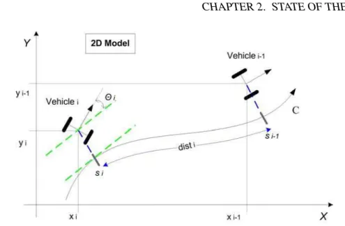
In this work, we consider platoons formed by a leader vehicle and followers. Leaders and followers have different control laws. We specify only the follower control law. Its aim is to keep as close as possible to the preceding vehicle while following a virtual ideal track without colliding. We use a model of vehicle where the control can be decomposed into longitudinal (i.e., speed and acceleration) and lateral (i.e., curve and wheel orientation) laws. We assume operating conditions such that the two controls can be computed independently.
There are numerous strategies to form and maintain platoons, characterized by their degree of centralization and the volume of communication. We specify a minimal strategy: no central control and no communication [Scheuer 2009] between vehicles other than perception, i.e., a vehicle can sense a few information from the preceding vehicle (distance, speed, etc.). The virtual track is set by the leader. The control is local to each vehicle, based on current state and perceptions. This strategy may not be one of
24 CHAPTER 2. STATE OF THE ART
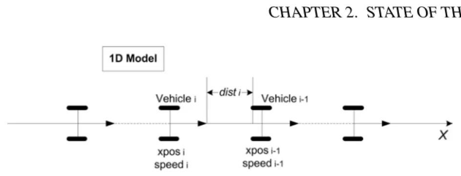
Figure 2.2: 1D platooning model
most efficient but it is very robust. In particular, it can be used as a fall-back in case of failure in a system using more sophisticated algorithms. Hence the need to guarantee its correctness.
Within this problem setting, platoons can be considered as situated multi-agent systems (MAS) which evolve following the Influence/Reaction model [Ferber 1996,Ferber 1999]. The development of the specification follows a stepwise refinement process based on this model: (i) driving systems perceive, (ii) decisions are taken, and (iii) physical vehicles move.
We aim at modeling a pragmatic strategy known as Daviet-Parent algorithm [Daviet 1996] in order to prove that implementations enjoy certain properties such as: (i) the model is sound bound-wise, (ii) no collision occurs between the vehicles, (iii) no unhooking occurs, and (iv) no oscillation occurs.
Presently, we focus on two essential safety properties: (i) soundness is maintained and (ii) no collision within a platoon occurs2.
2.6.2 1D Platooning Models
In the 1D platooning model, vehicles move on a linear track depicted in Figure2.2. It is formalized in classic B, Event-B and CSP||B. These models are proved to be correct.
Modeling in Classic B The specification described in [Simonin 2007] clearly separates the model of the physical world (environment) and the model of the vehicle behavior (agents). These two parts can be connected to express the full model, and separated to identify what are the specific properties that the model must verify. From the case study of the platooning problem, it proposed a generalized pattern to help the modeling of Influence/Reaction multi-agent systems.
Modeling in Event-B In [Lanoix 2008], the state of the ith vehicle at time t is the pair (xposi(t), speedi(t)), where xposi represents its position on the track and speedi represents its velocity. The longitudinal control consists in setting up an acceleration to
2. Collisions between platoons or between a vehicle and an obstacle should of course be considered in a real system. First kind should be taken care by the control law of leaders, second kind is dealt with by lower level emergency systems. Both are outside the scope of this work.