HAL Id: hal-01279286
https://hal.archives-ouvertes.fr/hal-01279286
Submitted on 25 Feb 2016HAL is a multi-disciplinary open access
archive for the deposit and dissemination of sci-entific research documents, whether they are pub-lished or not. The documents may come from teaching and research institutions in France or abroad, or from public or private research centers.
L’archive ouverte pluridisciplinaire HAL, est destinée au dépôt et à la diffusion de documents scientifiques de niveau recherche, publiés ou non, émanant des établissements d’enseignement et de recherche français ou étrangers, des laboratoires publics ou privés.
Thermo-magnetic behaviour of AFM–MFM cantilevers
Mithlesh Kumar, Richard Arinero, Wladimir Bergez, Philippe Tordjeman
To cite this version:
Mithlesh Kumar, Richard Arinero, Wladimir Bergez, Philippe Tordjeman. Thermo-magnetic be-haviour of AFM–MFM cantilevers. Measurement Science and Technology, IOP Publishing, 2015, 26 (8), pp.085002. �10.1088/0957-0233/26/8/085002�. �hal-01279286�
O
pen
A
rchive
T
OULOUSE
A
rchive
O
uverte (
OATAO
)
OATAO is an open access repository that collects the work of Toulouse researchers and
makes it freely available over the web where possible.
This is an author-deposited version published in :
http://oatao.univ-toulouse.fr/
Eprints ID : 15518
To link to this article :
DOI:10.1088/0957-0233/26/8/085002
URL :
http://dx.doi.org/10.1088/0957-0233/26/8/085002
To cite this version :
Kumar, Mithlesh and Arinero, Richard and Bergez, Wladimir and
Tordjeman, Philippe Thermo-magnetic behaviour of AFM–MFM
cantilevers. (2015) Measurement Science and Technology, vol. 26
(n° 8). 085002. ISSN 0957-0233
Any correspondence concerning this service should be sent to the repository
administrator:
[email protected]
1. Introduction
The behaviour of AFM cantilevers under a magnetic field is primarily known through a well-established technique called magnetic force microscopy (MFM) [1, 2]. If the tip approaches the sample surface to within a distance of typi-cally 10–500 nm, magnetic interaction of the tip with the stray field emanating from the sample becomes detectable. It is thus possible to explore magnetic domains with sub-micrometer spatial resolutions. MFM has been used to study the prop-erties of materials for magnetic recording media [3–5], to optimize the recording modes of magnetic heads [6], to inves-tigate the structure and properties of nanoparticles, alloys and nanocomposites [7] and thin films [8], and in the development of methods for magnetic recording with ultrahigh density [9]. MFM uses magnetized probes. In the dynamic mode, the reso-nance frequency or phase shifts are proportional to magnetic force gradients [3]. In order to quantify the observed effects, it has been common to use monopole and dipole approxima-tions to describe the MFM tip–sample interactions [10]. Metal rings carrying electrical current with inner diameters between 1 and 5 µm were used to calibrate the MFM tip’s effective magnetic charge and effective magnetic moment along the
tip axis [11–13]. Quantitative MFM has been strictly lim-ited to magnetic interactions at very short range under a very low magnetic field. This standard approach is convenient for many applications but it is not adapted to study quantitatively the local magnetic properties of condensed phases under an external magnetic field. To this end, it is important to separate the influence of the external magnetic field from the influence of the sample on the MFM probe.
Such studies are important to understand, for example, the orientation of magnetic domains (in bulk or thin films) under a dc or ac external field, or the magnetic instability of ferrofluids (peak patterning) where local response is closely related to the global excitation [14]. These studies require one to characterize the response of AFM cantilevers under an external magnetic field in the absence of samples.
In this paper, we investigate the force experienced by dif-ferent cantilevers due to the combined effects of a magnetic field and a temperature field, both produced by a dc current in a millimetric coil. This work shows that the cantilevers experience repulsion or attraction far from the coil and only attraction at short distance. The force depends mainly on the coating material as well as on the bulk material of the canti-levers. We point out that effects of temperature dominate the
Thermo-magnetic behaviour of AFM–MFM
cantilevers
M Kumar1,2, R Arinero1,3 W Bergez1 and Ph Tordjeman1
1 Université de Toulouse, INPT-CNRS, Institut de Mécanique des Fluides de Toulouse,
2 allée du Pr Camille Soula, 31400 Toulouse, France
2 CEA Cadarache, 13115 Saint-Paul-lez-Durance
3 Univ. Montpellier, IES, UMR 5214, F-34000, Montpellier, France
E-mail: [email protected]
Abstract
Atomic force microscopy (AFM) experiments were performed to study the behaviour of AFM cantilevers under an external magnetic field B and temperature field produced by a coil with an iron core. Four cantilever types were studied. Forces were measured for different B values and at various coil-to-cantilever separation distances. The results were analysed on the basis of a phenomenological model. This model contains the contribution of two terms, one monopole– monopole interaction at short distance, and one apparent paramagnetic interaction in ∇B2
at large distance, which represents the temperature effects. We observe a good agreement between the model and the experimental data.
Keywords: magnetic force microscopy (MFM), AFM, cantilever, coating, dc magnetic field.
M Kumar et al Printed in the UK 085002 Mst © 2015 IOP Publishing Ltd 2015 26
Meas. sci. technol.
Mst
0957-0233
10.1088/0957-0233/26/8/085002
Papers
8
Measurement science and technology IOP
interaction force at large distance while magnetic effects dom-inate at short distance. A phenomenological equivalent mag-netic model that takes into account the thermal effects can be used to predict the behaviour of cantilevers at the two scales. The paper is organized as follows: in section 2 we describe the materials and methods. The experimental results are presented in section 3 and are discussed in section 4.
2. Materials and methods
Different commercial AFM cantilevers were placed in the vicinity of a coil of NC turns (NC=40), with a core of iron,
carrying a dc current IC, as described in figure 1. z is the
dis-tance between the top surface of the iron core and the position of the fixed end of the cantilever. z is measured by the vertical piezo-transducer of the AFM.
The magnetic field produced by the coil as a function of the distance z is given by:
⎛ ⎝ ⎜ ⎜ ⎞ ⎠ ⎟ ⎟ μ ( ) = + − + + ( + ) B z N I h z R z z h R z h 2 , 0 C C C C2 2 C C2 C2 (1) where hC and RC are respectively the height and the radius of
the coil (hC ≈ 4.5 mm and RC ≈ 4 mm).
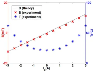
The relation between B and IC is linear as presented in
figure 2. For typical values of IC ranging from 0 to 3 A, the
field is constant in time and varies from 0 to 12 mT. The field calibration has been realized by means of a Hall effect Gaussmeter (GM07 from Hirst Magnetic Instruments Ltd) positioned in contact with the core at its centre. We have also measured a remanent magnetic field of 0.4 mT in the centre of the iron core when the current is switched off. In parallel, the temperature T of the iron core increases in IC2 by Joule heating
(figure 2). Consequently, in our experiments, the production of a magnetic field is systematically associated to a thermal field.
AFM experiments were performed with the Agilent™ 5500 in order to measure the force applied to cantilevers of different types when a dc current of various intensity is passing through the coil. For each cantilever, we determined the sensitivity
(nm V−1) by measuring the curve of voltage deflection versus vertical displacement when the tip comes in contact with the iron core or aluminium plate (contact mode). No lateral deflec-tion was observed in our experiments. Moreover, we checked that the stiffness calibrated by the thermal tuning method is in agreement with the value given by the manufacturers. Hence, it is straightforward to obtain the force applied to the cantilever in presence of a magnetic and thermal field from the stiffness and the sensitivity. The cantilevers are shown in figure 3. MFMR probes from Nanoworld™ are designed for MFM. They are made from highly doped monolithic silicon and their average stiffness k is equal to 2.8 N m−1. On the tip-side of the cantilever, a coating of approximately 40 nm thick cobalt alloy is deposited. On the reflector side, a 30 nm thick aluminum coating enhances the reflectance and prevents light from interfering within the cantilever. MESP from Bruker™ are also MFM probes where both tip and reflector sides are coated with a 50 nm thick CoCr layer. The cantilever stiffness is k≈3 N m−1. Hydra 6 V from AppNano™ are V-shaped soft cantilevers (k ≈ 0.08 N m−1) made of Si
3N4. The tip is made
of silicon and the reflector side is gold coated. Finally, we also used 3.7 N m−1 stiff, non-coated Si cantilevers (Fort from AppNano™). No further information was available on the composition and fabrication of coatings.
The experiments were realized with cantilevers taken from two or three different batches of the same type. Due to the fabrication process, cantilevers of the same batch have slightly different geometrical and material properties. For this reason, each measurement was repeated ten times with different cantilevers. The force values reported on the curves in this paper correspond to the average of these measurements given with a maximum standard deviation of 15%. The accuracy of the distance controlled by the piezo-transducer and of the magnetic field is ±1µm and ±10–2 mT, respectively.
To separate the effects of the magnetic field with those of the thermal field, we designed a small aluminium plate (1 × 1 cm2) heated by a straight Cu wire. No magnetic field
Figure 1. Schematic representation of the experimental set-up. An AFM probe is placed in an external magnetic field produced by a large coil with iron core. For a three-layer cantilever of total thickness h, e1 is the thickness of the coating on the tip side and e2
on the reflector side. Figure 2. Iron core temperature and magnetic field measured by a Hall effect Gaussmeter in contact with the iron core and comparison with the theoretical values for z=100µm.
was produced and the temperature could be varied from room temperature up to ~40 °C.
3. Experimental results
3.1. Effects of the magnetic and thermal fields
We consider, as a first example, the response at long probe-to-surface distance (z=100µm) of an MFMR cantilever in a
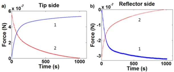
standard configuration, i.e. with the tip directed towards the surface. We refer this configuration as ‘tip side’. In the pres-ence of a dc magnetic field (B=10 mT and T=46°C), the
force versus time curve exhibits both short and long charac-teristic times, τ1 and τ2 respectively (figure 4(a)). The force is
positive, which means repulsion, and reaches relatively high values around 600 nN. After 1000 s, the current is switched off.
We observe a decay that is characterized by a slightly dif-ferent rate of variation. When the MFMR cantilever is turned upside down (backside directed towards the surface, ‘reflector side’ configuration), the force becomes attractive and its time variation shows the same characteristic times (figure 4(b)). We point out that the same transient regimes occur for both con-figurations, when the field is turned on and off. However, the magnitude of the force differs in the reflector side and tip side cases by a factor 2. The main result is that the force applied on the cantilever depends on the orientation of the cantilever. Applying a dc potential between the cantilever and the iron core, we also verified that the interaction force is not due to static electrical charges.
In terms of reproducibility, field-on or field-off repeated measurements showed a similar tendency with different MFMR cantilevers coming from the same batch. The values of τ1 and τ2 vary between 45–55 s and 400–500 s, respectively.
These two times are larger by some orders of magnitude than characteristic spin relaxation times. In consequence, the tran-sient effects do not seem to be linked to magnetism.
We have verified that τ1 does not match the time constant of
the equivalent RL circuit. The inductance and the resistance of the coil are L= μN Rπ
h 0 C2 C2 C and = ρ R L S w w w , where ρ =w 17 × 10 –9
Ω m, Lw = 0.1 m and Sw ≈ 10–9 m2 are the resistivity, the length
and the section area of the wire, respectively. The electrical time constant τ = L R/ is equal to a few µs, which is much lower than
τ1. This time seems to be related to the convective effects due to
direct heating of ambient air by the coil (the magnitude of the air velocity is of the order of gβΔTl, where β is the thermal expansion coefficient, ΔT the temperature difference between coil and ambient air and l is the height of the coil). Furthermore, the second time constant τ2 corresponds to the thermal diffusion
characteristic time corresponding to temperature equilibrium of the system: τ =2 2ChSp, where h is the natural convection
coeffi-cient corresponding to heat transfer between the iron core and air (h ≈ 18 W K m2 estimated from [15]), S is the area of the iron core
(S=6. 3 10× −5 m2) and C
p its heat capacity (Cp=1.1 J K−1).
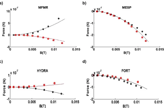
The variations of force with the magnetic field for the four cantilever types are presented in figure 5. For each value of Figure 3. Commercial AFM cantilevers used in the experiments.
Figure 4. Typical transient regimes observed at z=100µm for MFMR cantilevers when the magnetic field (B=10 mT) is turned on (curve 1) and then turned off (curve 2). (a) tip side configuration and (b) reflector side configuration.
magnetic field, a delay of 10 min is observed before the force is measured at z=100µm. All the results show that the
inter-action force varies as a function of B2. In the case of MFMR
(figure 5(a)), we clearly distinguish strong repulsive and attractive behaviours on tip and reflector side, respectively.
The dependence of the interaction force on the magnetic field is represented in figures 5(b)–(d) for MESP, HYDRA and FORT cantilevers, respectively. MESP cantilevers have the same coating on the tip and reflector sides and show the same attractive behaviour on both sides. HYDRA cantilevers are attracted on the tip side which is uncoated and repulsed on the reflector side which is gold coated. Finally, FORT can-tilevers, which are uncoated, are attracted on both sides. We note however a deviation between the results for the two ori-entations due to differences in the geometrical and material properties of the two sides. The forces are of the same order for MFMR, MESP and FORT cantilevers. On the other hand, the forces measured with HYDRA cantilevers are one order of magnitude lower. The attractive and repulsive behaviours are summarized in table 1.
3.2. Cantilever–coil distance effects
In this section, we present the variation of force as a function of distance for different dc magnetic fields. The results for the MFMR cantilevers are presented in figure 6. For each value of the magnetic field, the force exhibits two different behaviours for short range and long range distances: at short distance, the force is attractive whatever the orientation of the cantilever and scales as 1/− z2. The dependence is not measurable below
a few µm because the cantilever deflection is too large. At long distance, the force reaches an asymptotic value. It is repulsive for tip side cases and attractive for reflector side cases. The asymptotic value varies with the magnitude of B, as shown in figure 5(a).
The MESP probes display similar behaviour as MFMR, i.e. a − z1/ 2 force dependence at short distance and an asymptotic
force at long distance, which is now attractive for both tip side and reflector side orientations. These results are in agreement with figure 5(b).
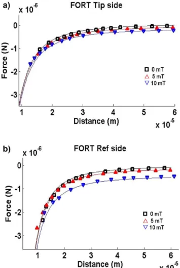
HYDRA cantilevers (figure 8) show the same short dis-tance trend as the other cantilever types. The asymptotic force values are coherent with figure 5(c). It was difficult to measure forces above 5 mT in the tip side configuration because of the low cantilever stiffness, which implies very large deflections. For example, considering k~ 0.08 N m−1 and a sensitivity factor χ ~ 100 nm V−1 between the signal of the photodetector and the deflection, the limit of 10 V of the photodetector is exceeded at forces above 80 nN. Experimental results with FORT cantilevers are represented in figure 9. Tip and reflector side responses present a similar attractive behaviour within the experimental uncertainties.
4. Discussion
4.1. Long range force model
In order to analyse the effects of large variations of temper-ature, we studied the long range response of the cantilevers using the aluminium plate heated by the Joule effect without Figure 5. Force versus magnetic field at z=100µm. Exprimental data: (⚪) tip side configuration; (◽) reflector side configuration. MFMR (a), MESP (b), HYDRA (c) and FORT (d). Solid lines: comparison with the model (equations (8) and (9)).
Table 1. Long distance (at z=100µm) attractive (A) or repulsive (R) response of the four cantilever types for tip side and reflector side
configurations. Apparent magnetic coefficients were obtained by fitting the experimental data.
Probe reference Apparent magnetic coefficients
MFMR R A Γ ≅ − × Γ ≅ × Γ ≅ 2.93 10 3.91 10 186 1 8 2 8 bulk MESP A A Γ = Γ ≅ × Γ ≅1 21862.84 10 4 bulk HYDRA A R Γ = Γ ≅ − × Γ ≅ × 0 1.66 10 8.31 10 1 2 8 bulk 6 FORT A A Γ = Γ = Γ ≅ 0 0 186 1 2 bulk
Figure 6. Magnetic force versus distance for MFMR probes, measured at different B values. (a) tip side configuration; (b) reflector side configuration. Solid lines: comparison with the model (equations (8)–(10)).
Figure 7. Magnetic force versus distance for MESP probes, measured at different B values. (a) tip side configuration; (b) reflector side configuration. Solid lines: comparison with the model (equations (8)–(10)).
a magnetic field. For all the cantilevers, we observed that the long range asymptotic forces (z > 100 µm) are of the same order of magnitude than those measured with the electrical coil. In particular, we found exactly the same attractive and repulsive responses when the orientations of the cantilevers were reversed. Hence, in the magnetic experiments, the ther-moelastic properties seem to control the long range behaviour by the temperature gradient effect and, for multilayer cantile-vers, by the difference in the coefficients of thermal expansion. In the framework of linear elasticity, the radius of curvature of the bent multilayer cantilever is given by:
∫
∫
ϵ = ( ) ( ) ( ) R E z z z E z z z z d d , 2 (2)where E z( ) is Young’s modulus at the position z in the canti-lever and ϵ( )z is the thermal deformation of the cantilever at z, which is proportional to the thermal expansion coefficients of the layers and their temperature variations [16]. When R << L, where L is the length of the cantilever, the deflection is δ ≈2LR2 and the bending force is F=kδ.
Equation (2) also takes into account the effects of the perature gradient in the cantilever. In case of a uniform tem-perature and a bimorph cantilever, equation (2) is similar to equation (4) in [17]. Modelling the cantilever bending requires precise values of the thicknesses and the thermoelastic film properties of the layers, and the geometry of the cantilever. With values of these parameters given in the literature, we obtain a good qualitative agreement with the experimental response of the cantilever: first, the maximum deflection scales as IC2 and
second, we find the same attractive and repulsive behaviour in tip and reflector side configurations (figure 5). However, the magnitudes of the forces are difficult to predict precisely due to the uncertainties in the physical data and the presence of the internal stresses.
We propose a simple phenomenological model based on the force balance of a multilayer cantilever that takes into account the main experimental observations at long range, i.e. the force is a square function of the electrical current and then of B2, and the specific behaviour of each cantilever in the tip
and reflector side configurations. This model was also devel-oped because it is easier to control the magnetic field via the electrical current (Biot–Savart law) than the temperature field Figure 8. Magnetic force versus distance for HYDRA probes,
measured at different B values. (a) tip side configuration; (b) reflector side configuration. Solid lines: comparison with the model (equations (8)–(10)).
Figure 9. Magnetic force versus distance for FORT probes, measured at different B values. (a) tip side configuration; (b) reflector side configuration. Solid lines: comparison with the model (equations (8)–(10)).
due to its highly non-linear behaviour. Moreover, the thermal properties of the multilayer cantilever are not always well established.
In the model, we consider that the cantilever is character-ized by its length L, width w and thickness h, and is clamped at one extremity. e1 and e2 are the thickness of the coating
layers on tip and reflectors sides, respectively (e e1, 2≪h).
Considering a cantilever substrate with thin film layers, equa-tion (2) can be approximated by the differential equation gov-erning the cantilever deflection y along the x-axis:
= ( ) y x M x EI d d , 2 2 (3) where E and I are Young’s modulus and the moment of inertia of the bulk substrate, and M the total bending moment. M and I are respectively given by M x( ) =
( )
ρ ( − )x L2
2, where ρ is the
force per unit length and I= wh12
3
. In the case of V-shaped cantilevers (HYDRA), this last expression must be multi-plied by 2. From the conditions at the clamped end, y( ) =0 0
and d 0 /dy( ) x=0, we obtain the general expression of the deflection: ρ ( ) = ( − − ) y x x EI xL L x 24 4 . 2 2 2 (4) The deflection is measured at the laser spot, x=0.95L. We postulate that the effects of orientation are due to the multi-layer structure of the cantilevers as shown in figure 1 and ρ is a function of B2. The force per unit length experienced by the
cantilever is given by ρ ρ ρ= +1 bulk+ρ2, where ρ1and ρ2 are the forces per unit length in the coating layers, and ρbulk is that experienced in the bulk substrate. By analogy with paramag-netism, we assume that the forces on the cantilever are:
ρ = we2μΓ ddBz , z 1 1 1 0 2 1 (5) ρ = we2μΓ ddBz , z 2 2 2 0 2 2 (6)
∫
ρ μ = Γw Bz z 2 d d d , z z bulk bulk 0 2 1 2 (7) where Γ1, Γ2 and Γbulk are ‘apparent magnetic coefficients’ oftip side, reflector side and bulk layers respectively, and μ0 is
the vacuum magnetic permeability. z1 and z2 are the vertical
positions of the coating layers defined as z1=z and z2= +z h
for the tip side configuration and z1= +z h and z2=z for the
reflector side configuration (figure 1).
At a constant tip-to-surface distance z, we deduce from equation (1) that ddBz2 and dd2 2zB2 are proportional to I2and
there-fore to B2, in such a way that ρ = KB2. By fitting the
experi-mental curves presented in figure 5, it is then possible to estimate K for both tip and reflector side configurations. From
the Taylor series expansions of ρ1 and ρ2 at z+h/2, we obtain for the tip side configuration:
ρ μ μ = ( Γ + Γ + Γ ) + ( Γ − Γ) + ( ) + + w B z e e h wh B z e e O h 2 d d 2 d d , z h z h 0 2 2 1 1 2 2 bulk 0 2 2 2 2 2 2 1 1 2 (8)
In the same way, the force per unit length for the reflector side configuration is:
ρ μ μ = ( Γ + Γ + Γ ) + ( Γ − Γ ) + ( ) + + w B z e e h wh B z e e O h 2 d d 2 d d . z h z h 0 2 2 1 1 2 2 bulk 0 2 2 2 2 1 1 2 2 2 (9)
The case of uncoated FORT cantilevers (see figure 5(d)), for which e1=0 and e2=0, has been used to determine Γ ≅ 186bulk in silicon based cantilevers (MFMR and MESP).
From this value it is possible to determine Γ1 and Γ2 coefficients
for MFMR and MESP by fitting the experimental data (figure
5) with the linear system (8) and (9). In the case of HYDRA probes, e1=0 in equations (8) and (9). All the apparent
mag-netic Γ coefficients were calculated from the fit of the aver-aged experimental data by standard linear regression and are reported in table 1.
We point out that the Γ coefficients obtained in this phe-nomenological model have no link with the standard magnetic susceptibilities and show sensitivity to the total thermal field. For example, the magnetic properties of the silicon material found in the literature [18] give an interaction force much lower in magnitude than what we have observed.
In figure 5, the experimental data are fitted by the model (equations (8) and (9)). We find a good agreement for the B2
dependence of the interaction force for all the cantilevers with a unique value of Γbulk for a Si substrate.
4.2. Full range force model
The variation of the interaction force with the distance plays two regimes, at short and long distance. At long dis-tance, the z dependence is derived from the applied magnetic field (equations (1) and (5)–(7)). At short distance, the inter-action force curves for different applied field converge to a unique one. Without any current, the cantilever is submitted to the remanent magnetic field of the iron core. When there is no magnetic field and no magnetization but heating (experi-ments with the aluminium plate), the force is of smaller magnitude and exhibits only capillary effects at short dis-tance. In the limit of short distance and in the presence of a magnetic field, the force–distance relation scales as − z1/ 2
for all the cantilevers (figures 6–9) and can be modelled by
monopole–monopole interaction. In such an approximation, the force is expressed as:
μ π = − F g g z 4 , monopoles 0 m probe msurface 2 (10) where gmprobe is the equivalent monopole associated with the
probe and gmsurface that associated with the sample surface. The
monopole model can be understood as an effect of local mag-netic field that can be decomposed in a multipolar expansion, in which the first monopole–monopole term dominates. In our experiments, the local force characterizes the magnetiza-tion of the iron surface. In other situamagnetiza-tions, this force could be measured to characterize the magnetization of a medium by an external field (such as, for instance, a ferrofluid).
From the experiments, we cannot determine the gm coef-ficients in equation (10) separately. Only the product of mag-netic monopole intensities gmprobeg
msurface can be estimated. These
values are obtained by fitting the raw data and are summarized in table 2. We note that the order of magnitude of all the mono-pole products is ~10−10 A2 m2, which could be used to estimate
the short distance interaction force for this iron core.
In order to determine the full range interaction force under-gone by the cantilevers, equations (8)–(10) can be combined. Figures 6–9 show the comparison between this full range
model and the experimental data, for which the Γ coefficients are identical to those calculated from figure 5. While the mul-tilayer model predicts the correct behaviour of the cantilever, the question remains of how the chemical composition and the process of fabrication affect the thermal and magnetic proper-ties of cantilevers. At long range, in addition to temperature, other physical effects can contribute to the bending of the can-tilevers, such as magnetostriction [19–21].
Based on this study, we can propose a method to develop MFM experiments to investigate the magnetic response of a given sample to a dc or ac external magnetic field. In order to obtain a good lateral resolution, the MFM tip has to be close to the sample surface (less than 50 nm). In this case, the force on the cantilever is dominated by monopole–monopole interac-tion. First, we have to find a cantilever characterized by a low
gmprobe value and a repulsive behaviour in the tip side
configura-tion (as MFMR) in order to increase the range of the measured force by the photodiode. Second, the cantilever stiffness must be large to limit the cantilever deflection in the presence of a large interaction force.
5. Conclusion
The study of the near-field behaviour of samples by AFM under an external magnetic field requires knowledge of the cantilever response in similar conditions. Therefore, we have characterized in this paper the response of the AFM cantile-vers to an external dc magnetic field. A coil with an iron core was used to produce the external magnetic field. The force exerted on the cantilever was measured by its deflection. The results for four types of cantilevers have been presented and discussed. We have measured both the effects of B and temperature. At long distance, we observed that the tempera-ture effects dominate while the magnetic effects dominate at short distance. We have proposed a phenomenological model based on two contributions: a monopole–monopole inter-action at short distance and a multilayer interinter-action at long distance characterized by a generalized paramagnetic force proportional to ∇B2 modelling the temperature effects. Based
on this work, it is possible to define the cantilever proper-ties that are adapted for the study of the mechanisms at the nanoscale occurring in magnetic samples under external magnetic fields.
Acknowledgments
We would like to thank Hervé Ayroles of ‘Signaux et Images’ team at IMFT Toulouse for his technical assistance, and Cédric Charvillat of CIRIMAT laboratory for AFM technical support. This work has been financially supported by CEA Cadarache and CNRS.
References
[1] Martin Y and Wickramasinghe H K 1987 Magnetic imaging by force microscopy with 1000 Å resolution Appl. Phys.
Lett.501455
[2] Sáenz J J, García N, Grütter P, Meyer E, Heinzelmann H, Wiesendanger R, Rosenthaler L, Hidber H R and
Güntherodt H J 1987 Observation of magnetic forces by the atomic force microscope J. Appl. Phys. 624293
[3] Prins M W J, Groeneveld R H M, Abraham D L, Schad R, van Kempen H and van Kesteren H W 1996 Scanning tunneling microscope for magneto-optical imaging J. Vac. Sci.
Technol. B 14 1206
[4] Manalis S, Babcock K, Massie J, Elings V and Dugas M 1995 Submicron studies of recording media using thin-film magnetic scanning probes Appl. Phys. Lett. 662585
[5] Philips G N and Suzuki T 1997 Quantitative analysis of written bit transitions in 5 Gbit/in2 media by magnetic force microscopy J. Magn. Magn. Mater. 175115
[6] Proksch R, Schmidt J, Austvold S and Skidmore G 1997 Direct observation of the high frequency write response of recording heads using the magnetic force microscope
J. Appl. Phys. 81 4522
[7] Gibbs M R J, Al-Khafaji M A, Rainforth W M, Davies H A, Babcock K, Chapman J N and Heyderman L 1995 A comparison of domain images obtained for nanophase alloys by magnetic force microscopy and high resolution Lorentz electron microscopy J. IEEE Trans. Magn.
313349
Table 2. Product of magnetic monopoles (gmprobeg
msurface in A m2 2)
obtained by fitting the experimental data for the four cantilever types for tip side and reflector side configurations.
Probe reference MFMR 1×10⁻¹⁰ 2×10⁻¹⁰ MESP 2.5×10⁻¹⁰ 2.5×10⁻¹⁰ HYDRA 3×10⁻¹⁰ 4.5×10⁻¹⁰ FORT 4.5×10⁻¹⁰ 5.5×10⁻¹⁰
[8] Hehn M, Cherifi-Khodjaoui K, Ounadjela K, Bucher J P and Arabski J 1997 Engineering magnetic responses in hcp cobalt thin films J. Magn. Magn. Mater. 165520
[9] Homma T, Kurokawa Y, Nakamura T, Osaka T and Otsuka I 1996 Magnetic force microscopy analysis of the micromagnetization mode of double-layered perpendicular magnetic recording media J. Vac. Sci. Technol. B 14 1184 [10] Hartmann U 1999 Magnetic force microscopy Annu. Rev.
Mater. Res.2953
[11] Lohau J, Kirsch S, Carl A, Dumpich G and Wassermann E F 1999 Quantitative determination of effective dipole and monopole moments of magnetic force microscopy tips
J. Appl. Phys.863410
[12] Kong L and Chou S Y 1997 Quantification of magnetic force microscopy using a micronscale current ring J. Appl. Phys.
815026
[13] Arie T, Yoshida N, Akita S and Nakayama Y 2001 Quantitative analysis of the magnetic properties of a carbon nanotube probe in magnetic force microscopy J. Phys. D: Appl. Phys. 34L43–5
[14] Chang C H, Tan C W, Miao J, Barbastathis G 2009 Self-assembled ferrofluid lithography: patterning micro
and nanostructures by controlling magnetic nanoparticules
Nanotechnology20495301
[15] Rohsenow W M, Hartnett J P and Cho Y I 1998 Handbook of
Heat Transfer 3rd edn (New York: McGraw-Hill) p 4.16 [16] Honda T, Arai K I and Yamaguchi M 1994 Fabrication of
magnetostrictive actuators using rare-earth (Tb,Sm)Fe thin films J. Appl. Phys. 75 6994
[17] Timoshenko S 1925 Analysis of bi-metal thermostats
J. Opt. Soc. Am.11233
[18] Haynes W M (ed) 2014 Handbook of Chemistry and Physics 94th edn (Internet Version) (Boca Raton, FL/London: CRC Press/Taylor and Francis)
[19] Guerrero V H and Wetherhold R C 2003 Magnetostrictive bending of cantilever beams and plates J. Appl. Phys.
946659
[20] du Trémolet de Lacheisserie E and Peuzin J C 1994 Magnetostriction and internal stresses in thin films: the cantilever method revisited J. Magn. Magn. Mater.
136189
[21] McCorkle P 1923 Magnetostriction and magnetoelectric effects in iron, nickel and cobalt Phys. Rev. 22271