Composite Cathodes for Lithium Rechargeable Batteries by
Elsa A. Olivetti B.S. Engineering Science University of Virginia, 2000
Submitted to the Department of Materials Science and Engineering in Partial Fulfillment of the Requirements for the Degree of Doctor of Philosophy in Materials Science and Engineering
at the
Massachusetts Institute of Technology June 2007
C2007 Massachusetts Institute of Technology All Rights Reserved
Signature of Author: Certified by: Certified by: Accepted by: MASSACHUSETTS INSTInTTE OF TECHNOLOGY
JUL 0 5 2007
De ment of atcals Science and Engineering May 7th, 2007
IF
If N 1 - I- VDonald R. Sadoway hn T.Elliott Professor o Materials Chemistry Thesis Supervisor
#ne M. Mayes
Toyota Professor of Materials Science and Engineering Thesis Supervisor
/2 up :; I
Samuel M. Allen POSCO Professor of Physical Metallurgy Chair, Departmental Committee on Graduate Students
Composite Cathodes for Lithium Rechargeable Batteries by
Elsa A. Olivetti
Submitted to the Department of Materials Science and Engineering on May 7th, 2007 in partial fulfillment of the requirements for the Degree of Doctor of Philosophy in Materials Science and Engineering Abstract:
The utility of incorporating continuous, nanoscale vanadium oxide phases within preferred domains of self-organizing copolymers was investigated towards the fabrication of composite, nanoarchitectured electrode materials for solid-state rechargeable batteries.
In situ growth of cathodic phases within ion-conducting copolymer domains was
explored as a means to control morphology and to increase the surface-area-to-volume ratio, thereby increasing the specific electrode area for faradaic reactions and decreasing ion diffusion distances within the electrode-active material.
Copolymers of microphase-separating rubbery block and graft copolymers, previously developed as solid electrolytes, provide a matrix for directing the synthesis of an inorganic battery-active phase. The copolymers include poly[(oxyethylene)9
methacrylate]-block-poly(butyl methacrylate) (POEM-b-PBMA) with a domain periodicity of -35 nm made by atom transfer radical polymerization, and
poly[(oxyethylene)9 methacrylate]-graft-poly(dimethyl siloxane) (POEM-g-PDMS) with
a domain periodicity of-17 nm made by free radical polymerization. The resulting microphase-separated polymer is a structure of alternating hydrophilic (Li-ion conducting) and hydrophobic regions.
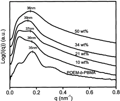
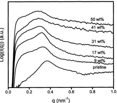
Sol-gel chemistry involving a vanadium alkoxide precursor enabled the in situ growth of cathode-active vanadium oxide within the continuous ion-conducting POEM domains of the microphase-separated copolymers. Resulting films, termed POEM-b-PBMA/VOx and POEM-g-PDMS/VOx, were freestanding and mechanically flexible. Small angle x-ray scattering and transmission electron microscopy revealed the nanoscale morphology of the composite and confirmed the spatially-selective incorporation of up to 34 wt% VOx in POEM-b-PBMA and 31 wt% in POEM-g-PDMS.
Electronically conductive components, necessary for wiring of the lithium-active vanadium oxide domains to the external circuit, were added through a variety of methods. Dispersions of acid-treated and cryo-ground carbon black within POEM-b-PBMA/VOx enabled the cycling of this material as a cathode. Reversible capacities of- 40 mAh/g were measured for batteries fitted with a polymer electrolyte doped with LiCF3SO3 and a
lithium foil anode. Electrolyte thickness studies indicated battery performance was limited by the ionic conductivity of the solid electrolyte. Using liquid electrolyte resulted in improved capacity (at higher currents) over conventional composite cathodes made from sol-gel derived vanadium oxide without the polymer matrix. The vanadium oxide nanoarchitecture was preserved upon removal of the polymer by heat treatment. The resulting templated vanadium oxide, when repotted with carbon black and binder,
exhibited improved capacity at high current over non-templated vanadium oxide cathodes. Thesis Supervisors: Donald R. Sadoway, John F. Elliott Professor of Materials Chemistry
Table of Contents: List of Figures List of Tables List of Abbreviations Acknowledgments Chapter 1 : Introduction... 13 Battery Overview ... 13 Battery M etrics... 16 Energy D ensity... 16 Pow er D ensity... 17 Cycle Life... 17
Tradeoffs in Battery Architecture: Energy Density vs. Power Density... 17
Polym ers for Structure-D irection Overview ... 22
Description of Thesis ... 23
References... 24
Chapter 2 : Literature R eview ... 26
Tem plating and Structure-D irecting w ith Polym ers... 26
Tem plating for Batteries ... 29
V anadium Oxide and V anadium Oxide Architectures ... 30
Electrochem istry of V anadium Oxide ... 34
Electronic Conductivity ... 38
Conjugated Polym ers... 40
Sum m ary and Introduction to the N ext Section... 44
References... 45
Chapter 3 : Processing and Characterization Techniques... 53
Polym er synthesis ... 53
M aterials ... 53
Block copolym er synthesis ... 53
Graft copolym er synthesis ... 55
A ctive Battery m aterial... 56
M aterials ... 56
Synthesis of Com posite ... 56
Electronic Conductivity ... 57
M aterials ... 57
Carbon Black ... 58
Conducting Polym ers... 59
Silver Salt... 60
Carbon N anotubes... 61
Electrochem ical Characterization... 61
M aterials ... 61
M ethods... 61
Techniques ... 62
Electrochem ical Tests Perform ed ... 63
Characterization techniques: Ex Situ... 66
Polym er Characterization... 66
Spectroscopy ... 66 Therm al Characterization... 67 Rheology... 67 Electron M icroscopy... 68 Surface Area... 68 References... 70
Chapter 4: Structure-Directed Vanadium Oxide ... 72
Polym er M atrix...72
Inorganic Characterization: POEM -b-PBM A/V Ox ... 77
Structure and Chem ical Characterization ... 77
Characterization of phases ... 82
Electrochem ical Characterization... 84
Inorganic Characterization: POEM -g-PDM S/V Ox... 86
Sum m ary... 91
References... 93
Chapter 5 : Electronic Conductivity ... 95
W ithout additive... 96
Silver Salt ... 97
PEDOT ... 100
Capacity of PEDOT ... 100
Carbon Black ... 113
Carbon black: Perform ance Lim itations of the Battery ... 119
Carbon black: A dvantages of system ... 120
Sum m ary... 122
References... 124
Chapter 6 : Benefits of Templated Architecture... 126
A W ord about Taxonom y ... 127
Rem oving the Tem plate... 127
Tem plate Rem oval: Changing the Atm osphere... 131
Calculating Potential Benefits of Architecture ... 137
M ass Transport... 139
Cycling D ata for Tem plated V Ox ... 140
D iscussion of Perform ance ... 142
Sum m ary... 145
References... 147
Chapter 7 : C ontributions of D issertation... 149
General Conclusions ... 149
Suggested Directions ... 151
Other applications ... 153
List of Figures:
Figure 1-1: A schematic of a rechargeable lithium battery upon discharge... 15
Figure 1-2: Schematic of the limiting kinetic processes within the electrodes... 20
Figure 1-3: Schematic showing morphologies of diblock copolymers. ... 22
Figure 2-1: Block copolymer nanoreactor scheme for metal nanocluster synthesis ... 28
Figure 2-2: Morphologies obtained from PI-b-PEO with varying amounts of alkoxides 29 Figure 2-3: Formation of V205 from sol gel process... 33
Figure 2-4: Discharge curve for crystalline and xerogel V205 ... . ... ... ... ... . . 35
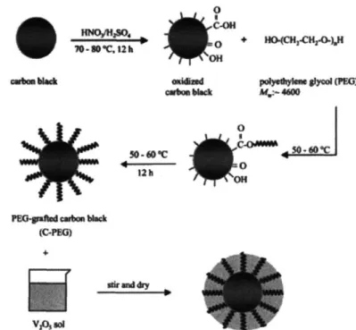
Figure 2-5: Process for coating V205 on PEG-carbon nanoparticles. ... 39
Figure 2-6: Chemical structure of poly(3,4-ethylene dioxythiophene) ... 42
Figure 2-7: Schematic diagram of assembly of PEDOT into V205 layers... 43
Figure 2-8: Charge-discharge cycles of Lii.m3Mnl.9704/PEDOT composite electrodes ... 44
Figure 3-1: POEM-b-PBMA chemical structure ... 55
Figure 3-2: POEM-g-PDMS chemical structure... 55
Figure 3-3: Scheme for growth of vanadium oxide in situ in the polymer domains ... 56
Figure 3-4: Scheme for adding carbon black to composite films ... 58
Figure 3-5: CVD reactor, Reproduced from Lock et al.[12]... 60
Figure 3-6: Coin cell used in battery testing... 61
Figure 3-7: Schematic of coin cell used in battery testing... 62
Figure 3-8: Schematic of 3-electrode cell showing WE, RE and CE ... 63
Figure 3-9: Schem atics of test cells . ... 65
Figure 4-1: SAXS and TEM characterization of pristine POEM-b-PBMA. ... 73
Figure 4-2: DSC trace for POEM -b-PBMA. ... 74
Figure 4-3: SAXS and TEM characterization of pristine POEM-g-PDMS... 74
Figure 4-4: DSC trace for POEM -g-PDM S... 75
Figure 4-5: Ionic conductivies measured by EIS for POEM and POEM-b-PBMA ... 76
Figure 4-6: Ionic conductivities measured by EIS of POEM and POEM-g-PDMS... 76
Figure 4-7: POEM-b-PBMA film incorporating 18 wt% VOx ... 77
Figure 4-8: Weight% of VOx from TGA as a function of precursor concentration ... 78
Figure 4-9: SAXS patterns for POEM-b-PBMA nanocomposite with vanadium oxide.. 78
Figure 4-10: TEM micrographs of POEM-b-PBMA containing 24 and 50 wt% V205 .. 79
Figure 4-11: STEM maps of POEM-b-PBMA containing 24 wt% vanadium oxide... 80
Figure 4-12: DSC trace of pristine polymer and after incorporation of vanadium oxide. 81 Figure 4-13: FTIR spectra for neat POEM-b-PBMA and POEM-b-PBMA/VOx ... 82
Figure 4-14: XPS spectra of V 2p peak for neat vanadium oxide and composite film .... 83
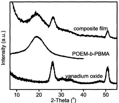
Figure 4-15: WAXS for POEM-b-PBMA, amorphous VOx and nanocomposite ... 84
Figure 4-16: CV for VO, and POEM-b-PBMA/VOx in LiClO4/PC electrolyte... 85
Figure 4-17: SAXS spectra for pristine POEM-g-PDMS and its nanocomposite films... 86
Figure 4-18: WAXS spectra for pristine POEM-g-PDMS and homopolymer... 87
Figure 4-19: WAXS spectra for pristine POEM-g-PDMS and nanocomposite films... 88
Figure 4-20: DSC curves for pristine POEM-g-PDMS and its nanocomposite films... 89
Figure 4-21: FT-IR spectra for pristine POEM-g-PDMS and its nanocomposite films... 90
Figure 4-22: Storage and loss moduli for pristine POEM-g-PDMS and nanocomposite .90 Figure 5-1: Galvanostatic cycling of POEM-b-PBMA/VOx film... 96
Figure 5-3: TEM of POEM-b-PBMA/VOx film containing Ag particles... 98
Figure 5-4: TEM of POEM-g-PDMS/VOx film containing Ag... 99
Figure 5-5: POEM-b-PBMA/VOx/Ag cycling data at C/20. ... 100
Figure 5-6: PEDOT deposition on Au electrode... 101
Figure 5-7: Cyclic voltammogram of PEDOT... 101
Figure 5-8: Charge/Discharge from the POEM-b-PBMA/VOx/PEDOT(CVD) film... 103
Figure 5-9: Capacity from POEM-b-PBMA/VOx/PEDOT(CVD) as cathode ... 103
Figure 5-10: Cross-sectional STEM of CVD PEDOT on POEM-b-PBMA/VO... 104
Figure 5-11: Higher magnification STEM micrograph with chemical map of sulfur.... 105
Figure 5-12: CV PEDOT deposition on VOx sputtered ITO and image of film... 106
Figure 5-13: PEDOT deposition onto POEM-b-PBMA/VOx coated Al wire mesh... 107
Figure 5-14: PEDOT deposition onto POEM-b-PBMA/VOx coated ITO glass slide .... 108
Figure 5-15: POEM-b-PBMA/VOx film containing PEDOT added as monomer... 108
Figure 5-16: CV of electropolymerization of EDOT w/POEM-b-PBMA/VO. ... 109
Figure 5-17: STEM mapping 0, S and V w/in POEM-b-PBMA/VOx/PEDOT...111
Figure 5-18: Cycling for 120 pm POEM-b-PBMA/VOx/PEDOT film at 2.5 pA/mg.... 112
Figure 5-19: Impedance plot of POEM-b-PBMA/VOx/PEDOT. ... 113
Figure 5-20: POEM-b-PBMA with 34 wt% VOx and 5 wt% CB... 114
Figure 5-21: TEM of POEM-b-PBMA w/34 wt% VO, and 5 wt% acid-treated CB... 115
Figure 5-22: Nyquist plot of POEM-b-PBMA/VOx with and without carbon black. .... 116
Figure 5-23: Cycling for POEM-b-PBMA/VOx/CB film with solid electrolyte... 117
Figure 5-24: Cycling for POEM-b-PBMA/VOx/CB (acid-treated & non-acid-treated) 118 Figure 5-25: CV for POEM-b-PBMA films w/VOx and/or CB (acid-treated)... 119
Figure 5-26: Discharge of POEM-b-PBMA/VOx/CB w/ varying electrolyte thickness. 120 Figure 5-27: Cycling data of POEM-b-PBMA/VOx/CB w/ current w/liquid elyte... 121
Figure 6-1: SEM of POEM-b-PBMA/VOx after polymer removal under Ar at 400*C. 128 Figure 6-2: Non-templated VOx synthesized and cast without polymer. ... 129
Figure 6-3: TEM of templated VOx heated to 600*C under argon and crushed... 129
Figure 6-4: Higher magnification TEM micrograph of templated VOx particles... 130
Figure 6-5: WAXS for sol-gel derived vanadium oxide heated at 400*C... 131
Figure 6-6: Ellingham diagram for vanadium oxide and carbon dioxide... 132
Figure 6-7: XPS V2p spectrum of sol-gel derived, non-templated vanadium oxide... 133
Figure 6-8: TEM of sol-gel derived, non-templated VOx ground for use in cathode... 133
Figure 6-9: XPS V2p of sol-gel derived, templated VO, heated 400*C under argon... 134
Figure 6-10: XPS V2p of sol-gel derived, templated VOx, heated 400*C under air... 134
Figure 6-11: TEM of sol-gel derived, templated VOx heated to 400*C in air... 135
Figure 6-12: XPS of VOx heated first in argon at 400*C, then heating in air to 400*C. 136 Figure 6-13: TEM of templated VOx heated at 400*C in argon, then heating in air... 136
Figure 6-14: V205 composite cathode cycled at different rates with liquid electrolyte.. 140
Figure 6-15: Discharge curves for templated and non-templated VO, at C/5... 141
Figure 6-16: 14t discharge curves for templated vs. non-templated composite cathodes. 142 Figure 6-17: SEM of composite cathode made with non-templated VO ... 143
Figure 6-18: SEM of composite cathode made from non-templated VOx at high mag.. 144
Figure 6-19: SEM of composite cathode made with templated VOx... 144
List of Tables:
Table 5-1: Table of capacity and depth calculation for POEM-b-PBMA/VOx/PEDOT. 112
Table 5-2: Conductivity values for various electronic conductivity additives... 123
Table 6-1: Elemental analysis on films with polymer removed under different atm ospheres... 136
Table 6-2: Surface area: volume comparing templated and non-templated VO... 138
Table 6-3: Capacity from templated and non-templated VO, at C/5... 141
List of Abbreviations:
AIBN = 2,2'-azobisisobutyonitrile initiator BET = brunauer, Emmet and Teller
CB = Carbon black
CCC = conventional composite cathode CV = cyclic voltammetry
DCM = dichloromethane
DI = deionized
FTIR = fourier transform infrared spectroscopy
GPC = gel permeation chromatography
HMTETA = 1,1,4,7,10,1 0-hexamethyltriethylenetetramine IPA= isopropyl alcohol
ITO = indium tin oxide
NMP = 1-methyl-2-pyrrolidinone
NMR = nuclear magnetic resonance
PANI= polyaniline PC = propylene carbonate
PEDOT = Poly (3,4-ethylene dioxythiophene) PEO = polyethylene oxide
POEM-b-PBMA = poly[(oxyethylene) methacrylate]-block-poly(butyl methacrylate) POEM-g-PDMS = poly[(oxyethylene), methacrylate]-graft-poly(dimethyl siloxane)
PPY = polypyrrole
PTFE = polytetrafluoroethylene PVDF = polyvinylidene fluoride
SAXS = small angle x-ray scattering
SEM = scanning electron microscopy
STEM = scanning transmission electron microscopy TEM = transmission electron microscopy
TGA = thermogravimetric analysis
THF = tetrahydrofuran
TMO = transition metal oxide
VO(O'Pr)3 = vanadyl triisopropoxide
VOx = vanadium oxide
WAXS = wide angle x-ray scattering XPS = x-ray photoelectron spectroscopy
Acknowledgments
First, I would like to thank my advisors, Professors Anne Mayes and Donald Sadoway for their patience and investment in my development as a scientist. Prof. Mayes' intellectual prowess, scientific curiosity, and attention to detail have taught me so much. She has touched the lives of many at MIT and the greater polymer community. Professor Sadoway has always entrusted me to learn from my mistakes, teaching me how to think independently. I have also appreciated his incredible teaching skills, precise use of language, and command of an audience. I am grateful to both of them for their encouragement, advice throughout the years, and tremendous support.
I would also like to thank my committee members, Prof. Robert Cohen and Prof. Yang Shao-Horn. Prof. Cohen met with me early on to shape this work and his students, Yot Boontongkong and Tom Wang, helped with my attempts at electroless deposition. Prof. Shao-Horn's post-doctoral researchers, Sundeep Kumar and more recently Naoaki Yabuuchi, have provided helpful input.
Several other researchers have helped with this work and I would like to thank them for their assistance. During his tenure at MIT, Dr. Jong Hak Kim was instrumental
in the progress of my research and helped with polymer synthesis, FTIR and mechanical property testing. Ayse Asetakin performed all of the XPS in this thesis and her cheerful disposition always made each day a little brighter. Dr. Ikuo Tanaguichi helped with the polymer synthesis, and I appreciated our conversations throughout my graduate
experience. He has taught us all so much and I am very grateful for his time with the Mayes group. Ken Avery helped with some of the SEM and provided much needed conversations on batteries as well as all things pertaining to life. Sung Gap Im in Prof. Karen Gleason's group did the PEDOT CVD and helped me a great deal with the world of electronically conducting polymers. Dr. Aislinn Sirk joined the Sadoway group at a critical time for me and I have thoroughly enjoyed her lessons in three-electrode
electrochemistry, her dedication to research, the spirit and community that she brought to the group, and for her companionship, not to mention editing this document many times over.
One of the best parts of my experience in graduate school has been the
opportunity to develop skills in electron microscopy, which would not have been possible without the impeccable instruction of Mike Frongillo and Dr. Tony Garrett-Reed. Tony also helped with the STEM work and provided much guidance about the use of EDX in sample analysis. Thank you also to David Bell who taught me all about "modern
microscopes" and the recent help from Yong Zhang with the FEG TEM. I learned microscopy sample preparatory skills from (and with) Patrick Boisvert, Jongseung Yoon and Juan Gonzalez who helped align moons when it was time to microtome.
I would also like to extend my gratitude to Patrick Trapa and Simon Mui who have helped with the science all along the way, even from afar, and for their great
horn/piano music at my wedding. Thank you also to Will Kuhlman for his help with spin-coating, NMR and great science conversation over the green glow of the TEM phosphor screen. Nava Ariel has been a great friend throughout and I am grateful for her help in
teaching me the secrets to good microscopy. Thank you to Dilan Seneviratne for his help with the heat treatment portion of my thesis and for the use of Old Faithful. I would also like to thank my undergraduate mentors: Professors Robert Kelly and David Kaplan. In addition, thank you to Jodie Lutkenhaus, Rachel Pytel, Shirley Meng, Vahik Krikorian, Elisa Alonso and Lenny Rigione. I am also very grateful for the support of past and present labmates, Solar Olugebefola, Ozge Akbulut, Nathan Lovell, Ariya Akthakul, Heather Stem, David Bradwell, Andrew Gmitter, Chanaka de Alwis, Dihua Wang, Bing Li and the great help of lab UROPs, Harold Hsiung, Boris Rasin and Alex Konings. I am also very grateful for all the support and help from Jenna Picceri and Hilary Sheldon.
Thank you also to the sponsors of this work: the Office of Naval Research under Contract numbers N00014-02-1-0226 and N00014-05-1-0056 and in part by the MIT MRSEC Program of the National Science Foundation under Award number DMR-0213282.
The support and patience of my friends and family has been tremendous, truly overwhelming and something I will never be able to repay. My parents have been endlessly supportive and encouraging of my work and I owe a special thank you to my dad for providing inspiration for the first paragraph of this thesis. My fabulous sister has been crucial to keeping it all in perspective by providing the soundtrack to my graduate experience and many visits when she was in the neighborhood. And to Justin, thank you so much for being my teammate and companion through all of this, and thank you to your family for their never ending support.
Chapter 1 : Introduction
A recent New York Times article described General Motors' introduction of its new hybrid vehicle, the Volt, at the North American International Auto Show. This vehicle is projected to travel up to 40 miles on batteries alone (longer than the daily distance traveled by almost 80% of U.S. commuters) [1] and would charge its long cylindrical battery pack through an onboard generator or a household plug-in. As described by GM, the Volt has one major challenge, "the battery technology to make it roadworthy does not yet exist," meaning a battery that meets these requirements has not yet been developed.[2]
The challenge for battery scientists with regard to electric vehicles is to develop small, light batteries that can achieve a real-world target for driving distance, such as the 40 miles mentioned above, before recharging. The U.S. Advanced Battery Consortium has set criteria for EV applications, which include a lifetime of 10 years, a cycle life of
1000 cycles along with a recharge time of between 3 and 6 hours at < $1 00/kWh.1 As the United States seeks solutions to alleviate its dependence on fossil fuels, which contribute to greenhouse gas emissions and make the country dependent on foreign energy sources, there is great demand for improved energy storage devices.
This thesis studies possible modifications in current battery architectures, more specifically in cathode materials, to improve overall performance specifically and investigates the relevant materials science because, as MIT Professor Donald Sadoway has observed, "the road to autonomy is paved with advanced materials."[3]
Battery Overview
A rechargeable lithium battery operates due to a gradient in the chemical potential of lithium between the anode and cathode. A schematic of a typical rechargeable battery is shown in Figure 1-1. Upon discharge, lithium ions move from the anode to the cathode. If pure lithium metal is used as the anode, a charge transfer step will take place, Li -> Li+ + e-, and the soluble lithium ions will diffuse through the ionically conducting,
electronically insulating electrolyte. When the ions reach the cathode particles and insert,
their presence causes a valence shift in the transition metal oxide cathode material. This, in turn, calls for a compensating electron from the external circuit (supplied from the reaction at the anode). The electrode reactions for charge and discharge of the
intercalation compound cathode and pure lithium metal anode are shown in Equation 1-1 and Equation 1-2.
At the Li metal anode: yLi' + ye (- yLi
Equation 1-1
At the cathode:
Lix+z[(2-x-z)M"*, (x+z)MC" -]Oy<tyLi+ + Lix[(2-x)M"*, xM"-]Oy + ye-Equation 1-2 where LiMOy is a lithiated transition metal oxide. Or for Li-ion cells, where insertion occurs at both electrodes, using lithiated carbon on the anode side gives Equation 1-3.
At the anode: C + yLi+ + ye~ <- - LiC
Equation 1-3 where the system moves towards the right on charge and towards the left on
discharge. On discharge oxidation occurs at the anode, while on charging reduction occurs at the "anode."
As depicted in Figure 1-1, the conventional cathode contains several elements, including the battery active material (transition metal oxide), a conductivity additive (carbon black particles), and a polymer binder that combines the elements of this composite cathode.
LM MO elelyte currentcurrent collecctor curret - 0couret colcollector (Al) (9u)+
Anode Electrolyte Cathode
Figure 1-1: A schematic of a rechargeable lithium battery upon discharge. The electrolyte of a rechargeable lithium battery must be ionically conducting but electronically insulating to allow Li* to pass but to prevent self discharge of the cell. The electrolyte may consist of a liquid organic solvent containing a high concentration of dissolved lithium salts. However, there are safety concerns and degradation issues
associated with liquid electrolytes. To address these issues, liquid-like characteristics may be introduced to a solid electrolyte in the form of plasticizers, or an entirely solid
electrolyte may be used.
Typical solid electrolytes are made of polyethylene oxide (PEO), which is able to dissolve lithium salt and become an ion conductor. The high molecular weight that makes this polymer solid also increases the polymer's crystallinity and, as a result, lowers the ionic mobility and therefore the conductivity. Additives to suppress crystallinity, such as clays or other inorganic components, have been incorporated into the polymer with some success.[4, 5] In our laboratory a family of polymer electrolytes consisting of a hydrophilic, ion-conducting block component (PEO-based) covalently bound to a
hydrophobic, mechanically stabilizing block, have been developed. The PEO-based block is amorphous due to its comb-like architecture incorporating short PEO side chains, while the hydrophobic component confers solid-like characteristics upon microphase separation, increasing mechanical stability.[6, 7]
The choice of material and architecture for each element of a battery (anode, cathode and electrolyte as well as current collectors and packaging) will affect the overall system performance. The chemical potential gradient between the anode and the cathode
determines the voltage of the cell, while the amount of charge (Lie) stored by the cell determines the capacity. To compare batteries of different chemistries, capacity is often normalized by either the weight or volume of the cell. Another important consideration for materials choice is the rate capability, which is the rate transfer of energy, i.e., current, determined by the kinetics of various rate phenomena. Other important parameters
include safety and cycle life. Recent explosions of lithium ion cells in laptops due to several potential factors, including thermal runaway (addressed by altering the cathode chemistry) and the volatility and flammability of the electrolyte have brought about renewed interest in safety.[8] Sony, the company responsible for the manufacture of these batteries, has reported that the cost of recalling 9.9 million laptop computer batteries was $429 million.[9] There are tradeoffs between electrolytes, however, as a solid electrolyte is advantageous from a safety perspective, but the ionic conductivity and therefore rate capability can be reduced.
The next section will describe relevant battery metrics and discuss the relationship between the metrics addressed in this work.
Battery Metrics
Depending on which chemistries and architectures are chosen for a battery, different applications and technologies can be targeted. This work focuses on
rechargeable batteries that can be cycled readily through monotonic charge and discharge cycles. The key performance indicators for rechargeable batteries are high discharge current, large capacity, quick rechargeability, long shelf life (stable voltage) and long cycle life. Three related metrics that capture several of these characteristics are energy density, power density and cycle life. The following sections explain these metrics in detail.
Energy Density
Energy density refers to the amount of electrical energy available from the battery in a single discharge cycle, expressed in energy/mass (Wh/kg) or energy/volume (Wh/L) of battery material (which can be defined for either the electrode material or the entire battery). The theoretical energy density (Wh/kg) of a battery is determined by the product
of the battery voltage (V) times the charge capacity (Ah/kg) of the system2. The actual energy density of a battery is always less than the theoretical value due to the inactive materials such as the electrolyte, conductivity additives, current collectors and packaging. Also, there are the inevitable energy loss mechanisms that become more significant at higher discharge rates (higher power), most notably the ohmic drop, which is the product of the current through the device and its internal resistance.
Power Density
The rate at which energy is delivered to or from the battery defines its power (expressed in W or kW). The maximum power a battery can deliver or accept is determined by the highest rate at which the battery can be discharged/charged and is governed by kinetic processes within the battery. The specific power (W/kg) is given by the battery voltage (V) times the battery discharge rate (A/kg). The discharge rate can
also be expressed in terms of a C-rate. 1 C is the current rate that would fully discharge the capacity of the cell in 1 hour, a 2C rate indicates full discharge/charge in 30 minutes, and a C-rate of /2 indicates full discharge/charge in 2 hours.
Cycle Life
Cycle life is defined as the number of charge/discharge cycles a battery can tolerate before it becomes unusable in a specific application. The cycle life is highly dependent on the depth of discharge of each cycle, with the cycle life decreasing
drastically with higher depths of discharge when discharge cycles extend into irreversible regimes due to irreversible phase transformations.
Tradeoffs in Battery Architecture: Energy Density vs. Power
Density
Battery chemistry and morphology will determine the limits of energy density and power density in a cell. The energy density is determined by the thermodynamics of the system (the potential difference between the anode and the cathode). The power density is determined by the kinetic processes such as electron transfer (reaction rate), mass transport within the cathode (diffusion length scales), and ion transport within the
2 the product of the number of lithium ions, n, inserted per molecular mass, M, of the cathode times the
electrolyte. These processes result in more significant energy losses when the battery is operated at the higher end of its power capabilities (high C rate). Thus, for high power operation, a battery must have high Li* diffusion rates within the active material in the anode and the cathode, high electronic conductivity within the anode and cathode, high diffusion rates of ions through the electrolyte, and fast reaction rates at the cathode and anode surfaces. If any of these are sluggish, the properties of the battery as a whole are affected.
There are several mechanisms by which the power or energy density of the cell can be adversely affected. These voltage losses, detailed below in Equation 1-4, are described in the subsequent paragraphs.[10]
AE = Ecath - Eanodic - IR - 7lcath - 1lanode - lmass trans
Equation 1-4 Losses may be associated with electronic resistance in the electrodes. These IR losses are mitigated by developing electrode materials with higher intrinsic conductivities or by using composite electrodes consisting of active electrode materials mixed with higher conductivity inactive materials.
Kinetic losses associated with driving the faradaic processes at the
electrode/electrolyte interfaces are termed charge transfer or overpotential losses, lceath
and flanode.[ 11] These losses are minimized by using electrode/electrolyte pairs that have intrinsically high catalytic activities for the reactions involved and by maximizing the electrode/electrolyte interfacial area. The maximization of electrode/electrolyte interface can be achieved by making porous electrodes consisting of very small active particles (nanoparticles) or by increasing the total surface area.
The active materials' structure and particle size largely determine the diffusion rates of lithium ions within the anode and cathode. Losses associated with these diffusion processes are typically termed mass transport limitations, lmass trans. [11] The development and use of materials with high intrinsic diffusivities helps mitigate this loss mechanism. The use of smaller particles (i.e. nanomaterials) shortens the distance ions need to diffuse.
The intercalation ability of Li into the cathode is limited by its diffusion in the solid, which hinders performance at higher rates of discharge. Therefore, increasing the
thickness of the electrode to increase its energy density will increase the diffusion penetration time as L2/D (where D is the diffusion coefficient and L is the electrode
thickness). Porous electrode structures will overcome diffusion limitations even in thicker films if there is electrolyte penetration. To illustrate the dependence of diffusion time on particle size, consider particles of diameter 50 and 5 pm along with a film that is 500 nm thick. Assuming a diffusion coefficient of 10-13 cm2/s, the diffusion time through the inorganic would be 70,000, 700 and 7 hours, respectively.[12]
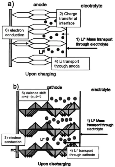
The schematic in Figure 1-2 illustrates the various forms of transport within the cathode/electrolyte interface that are enhanced by increasing the surface-area-to-volume ratio. Both slow transfer kinetics and slow lithium diffusion can be aided by increasing this ratio. Figure 1-2a illustrates the case of a graphite carbon anode upon charging. The processes of interest include the mass transport of Li* through the electrolyte (1), the charge transfer across the electrode/electrolyte interface (2), and metallic lithium transport (4) through the anode. Electronic conduction (6) through the anode is also necessary for charge to pass through the external circuit. So that the ingress of lithium was illustrated in both electrodes, Figure 1-2b shows the cathode upon discharging. Additional kinetic processes occurring in this intercalation cathode that may be improved by increasing the surface-area-to-volume ratio include: mass transport of Li+ through the galleries of the cathode (4), compensating valence shift in the transition metal oxide (5) and electronic wiring of the cathode, enabling current to travel through the external circuit (3). The cathode must be a mixed conductor of ions and electrons to facilitate electron motion in the presence of Li+ motion. In vanadium oxide, the cathode material studied in the thesis, conduction occurs by polaron hopping associated with V4+ and V5+
valence shifts. A "front" of charge transfer moves through the TMO cathode as Li* intercalates and destabilizes the V5*.
anode electrolyte
1)
U+
M- tnpr
through elolyte Upon charging 3) electron g conduction L 4) U+ transport through cathode Upon dishargingFigure 1-2: Schematic of the limiting kinetic processes within and at the electrode/electrolyte interface of a) LiC6 carbon anode (upon charging) b)
intercalation cathode (upon discharging).
Overall, in designing an optimal electrode material one seeks to use a large fraction of the electrode in the reversible redox reaction, to maintain electrical
conductivity within the cathode, and present a high particle/electrolyte surface area over many discharge/charge cycles. The solid-state Li-ion diffusion coefficient (intrinsic to the material) and diffusion lengths may limit the kinetics (mass transfer effects) of these devices. Therefore, the rate capability or power performance of a battery is greatly influenced by the size of the particles making up the electrodes and by the electrode surface area. Improved power density exists in high surface area structures because the distance over which Li+ must diffuse in the solid-state is shorter. Critical interface area becomes more important as ionic conductivity decreases. A host material that provides a
larger free volume for Li' motion in the interstitial space would allow realization of higher Li+ conductivity and hence higher power densities. In addition, at high discharge rates, high Li+ insertion flux density and slow Li* transport result in concentration polarization of lithium within the electrode material. This phenomenon causes a drop in cell voltage, which results in termination of the discharge before accessing the full capacity of the electrode material. Improved rate capabilities delay the onset of concentration polarization.
However, a tradeoff exists between those battery systems with high energy density and those with high power density.[13, 14] The former requires electrodes with high capacity, high voltage, and a low mass of inactive materials (such as conductivity and polymeric binder additives). Systems with thin current collectors and thick, low porosity electrodes fit this profile. On the other hand, systems aiming for high power density use electrodes with low resistance but high voltage focus on thin, highly porous electrodes to reduce diffusion distances and high surface area. Often an increase in power density comes at the expense of energy density.
Other issues affecting the cycle life of a battery include particles becoming isolated from electronic additives, or other cathode particles, upon cycling because of volume excursions in the active battery phase.[14] Battery lifetime is determined by mechanical and chemical degradation that occurs during battery cycling. During charge and discharge, battery electrodes experience phase transformations between crystal structures of different volumes; for example, the layered phase reversing to the spinel with cycling in LiMn204.[15] Thus, during cycling, significant volume changes occur,
introducing mechanical stresses into the device that ultimately break down battery structural integrity. Furthermore, irreversible parasitic chemical reactions between the electrolyte and the electrodes or dendrite formation can change the electrode/electrolyte interface, thus limiting battery cycle life.[15]
This thesis will focus on the cathode, which is generally the limiting factor in improving rate capability.[16] To develop an alternative cathode material, block and graft copolymers, developed by our lab group as electrolytes for rechargeable batteries,
are used to structure-direct the growth of an active phase within the nanoscale domains of the polymer. The next section will briefly describe the properties of these polymers.
Polymers for Structure-Direction Overview
Block copolymers consist of two or more chemically distinct polymer block components that are covalently linked. When many copolymer chains are mixed, mutual repulsion between chemically dissimilar blocks causes them to segregate to form like domains. Chemical bonds between the two blocks limit their separation to the nanoscale, and the resulting morphologies seek to lower their interfacial energy. Therefore, different self-assembling morphologies can be achieved by changing the relative amounts of the two polymer components. The equilibrium polymer morphologies can range from body-center cubic packed spheres of one block in a matrix of the other to bicontinuous
networks of each, as shown in Figure 1-3.
Figure 1-3: Schematic showing different morphologies of non-crystalline linear diblock copolymers. Reproduced from Park et a!. [17]
This microphase-separating characteristic of copolymers has been used to structure direct the growth of inorganic phases within one block domain, relying on strategies such as differences in solubility or chemical tethering.[17-19] The current work employs microphase-separating block and graft copolymer electrolytes, previously developed in this group as electrolyte materials, and repurposes them as a matrix for the
in situ growth of nanoscale vanadium oxide morphologies which serve as a battery active
phase within the ion-conducting domains of the polymer. Increasing the surface-area-to-volume ratio within the cathode is expected to improve battery performance when it is limited by mass transfer. The enhanced performance is due both to reduced Li* diffusion
Nwa,. of SOM 00d Dul Doubs. LaM~A
Pa-
-
Dhn GM m m= m -ft hdd Pm!,m PM danubs: Abm VM tmo 0-21% 21-33% 33-37% 37-W0% of AbMAIdistances and to increased surface area over which faradaic reactions can occur. In
addition, using a solid electrolyte with a cathode of similar composition may improve the kinetics at the electrode/electrolyte interface. The solid electrolyte also addresses safety issues present with a flammable organic liquid electrolyte and facilitates the formation of a fully solid-state device that can be made mechanically flexible.
This thesis investigates the use of microphase-separating copolymer electrolytes to generate cathode architectures.
Some of the questions this dissertation will address are:
1. Can microphase-separated polymers be used to direct the growth of cathode active materials, such as transition metal oxides?
2. Are the resulting microstructures continuous and on an appropriate size scale? 3. Can these structure-directed materials be used as cathodes? What electronic
conductivity additives are necessary to make them usable?
4. Do these nanocomposites offer an improvement to a particular set of battery metrics, e.g. rate capability?
Description of Thesis
The next chapter provides a review of relevant literature, describing current approaches to cathode architecture, block copolymer templating and vanadium oxide's use as a cathode material. Chapter 3 describes the experimental techniques and synthesis strategies that make up the body of this work. Chapters 4-6 elaborate on the cathode films that were synthesized, their chemical and electrochemical characterization and their use in battery test cells. Chapter 4 focuses on the incorporation of vanadium oxide through sol-gel chemistries into the block copolymer, POEM-b-PBMA, and the graft copolymer POEM-g-PDMS to form a nanocomposite film. Electronic conductivity is necessary for the nanocomposite to function as a cathode, so Chapter 5 describes approaches to incorporating electronically components such as poly (3,4-ethylene dioxythiophene) and carbon black. In Chapter 6, the nano-architecture is explored in a composite cathode without the polymer to evaluate battery metrics. Finally, Chapter 7 summarizes the accomplishments of this thesis and provides recommendations for future research.
References
1. "NHTS 2001 Highlights Report, BTSO3-05" by US Department of Transportation, 2.
2. Brooke, L.,"All the Technology Needed for 100 mgp (Batteries Not Included)" in
New York Times, January 7, 2006, 2, 12.
3. Sadoway, D. R. (2005).
4. Walls, H. J., Singhal, R. R., Spontak, R. J., Fedkiw, P. S. & Khan, S. A.
"Nanocomposite Electrolytes with Fumed Silica and Hectoriate Clay Networks: Passive versus Active Fillers." Advanced Functional Materials, 2003, 13, 710-717. 5. Kurian, M., Galvin, M., Trapa, P. E., Sadoway, D. R. & Mayes, A. M. "Single-ion
conducting polymer-silicate nanocomposite electrolytes for lithium battery applications." Electrochimica Acta, 2005, 50, 2125-2134.
6. Trapa, P. E., Huang, B., Won, Y.-Y., Sadoway, D. R. & Mayes, A. M. "Block Copolymer Electrolytes Synthesized by Atom Transfer Radical Polymerization for Solid-State, Thin-Film Batteries." Electrochemical and Solid-State Letters, 2002, 5, A85-A88.
7. Trapa, P. E. et al. "Rubbery Graft Copolymer Electrolytes for Solid-State, Thin-film Lithium Batteries." Journal of the Electrochemical Society, 2005, 152, A l-A5.
8. AP posting,"Sony Says Recall Strains Battery Production" in New York Times, 5, C.
9. Darlin, D.,"Reluctance and Silence on Recalls" in New York Times, October 28, 2006, 1, C.
10. Stender, W. W., Zivotinsky, P. B. & Stroganoff, M. M. "The voltage balance of a cell for the electrolysis of sodium chloride solutions. Distribution of voltage drop through the (Vorce) cells with vertical filtering diaphragms." Transactions of the
Electrochemical Society, 1934, 65, 24.
11. Bard, A. J. & Faulkner, L. R. Electrochemical Methods John Wiley & Sons: New York, 2001.
12. Tipton, A. L., S., P., Owens, B. B. & Smyrl, W. H. "Performance of
Lithium/V205 Xerogel Coin Cells." Journal of the Electrochemical Society, 1996,
143, A221-A223.
13. Doyle, M. & Newman, J. "Analysis of Capacity-rate Data for Lithium Batteries using Simplified Models of the Discharge Process." Journal ofAppled
Electrochemistry, 1997, 27, 846-856.
14. Linden, D. Handbook ofBatteries McGraw-Hill: New York, 2001.
15. Tarascon, J. M. & Armand, M. "Issues and Challenges Facing Rechargeable Lithium Batteries." Nature, 2001, 414, 359-367.
16. Sadoway, D. R. & Mayes, A. M. "Portable Power: Advanced rechargeable lithium batteries." MRS Bulletin, 2002, 27, 590-592.
17. Park, C., Yoon, J. & Thomas, E. L. "Enabling Nanotechnology with Self Assembled Block Copolymer Patterns." Polymer, 2003, 44, 6725-6760.
18. Cohen, R. E. "Block Copolymers as Templates for Functional Materials." Current
Opinion in Solid State and Materials Science, 1999, 4, 587-590.
19. Templin, M. et al. "Organically Modified Aluminosilicate Mesostructures from Block Copolymer Phases." Science, 1997, 278, 1795-1798.
Chapter 2 : Literature Review
This chapter summarizes relevant literature covering the methods and materials used in this dissertation. It begins with a discussion of block copolymers as templates to direct the growth of inorganic compounds. Next, it describes the transition metal oxide, vanadium oxide, and its use in lithium battery cathodes, as well as modifications to oxide cathode architecture. Finally, it presents relevant approaches to increase electronic
conductivity within the cathode.
Templating and Structure-Directing with Polymers
When block copolymers are combined with inorganic compounds the composites that result include the properties of the organic host and the inorganic phase, thereby generating a variety of novel materials for magnetic, electronic or photonic applications. The interest in developing hybrid organic-inorganic, self-assembling materials stems from the small scale of microdomains and the tunability of size, shape and periodicity of these composites, which should lead to improved transport, mechanical, electrical and optical properties. Resulting materials are predicted to have larger surface-area-to-volume ratios and possibly desired quantum size effects. Current applications include contact lenses, scratch-resistant coatings, chemical filters and dental fillings.[ 1] Future
applications, such as interconnects, sensors or lithography, could take advantage of other tunable properties including high anisotropy and high local dielectric contrast. Further tunability arises from the ability to control microstructure through application of applied fields.[2] Applications in nanotechnology have included micelles for drug delivery, formation of metal or ceramic nanodots and wires, as well as photonic crystals and masks for high density information storage.[1] The challenge and limit of these structures for many applications comes in the ability to control for defects and domain orientation on a large scale.
There are numerous examples of block copolymer templating found in the literature. This section will describe some that are most applicable to this research. Much of the seminal work describing structure-direction of inorganic compounds with organic species was done by Stucky and coworkers at the University of California, Santa Barbara.
In their most cited paper, Yang et al. described the use of surfactants and poly(alkylene oxide) block copolymers to form mesostructured systems for a variety of metal oxides and mixed oxides including TiO2, A1203, W03, SnO2, and others.[3] They have also used
these structure-directing agents to form highly ordered mesoporous silica structures in acidic media, some with surface areas as high as 1000 m2/g.[4] A recent investigation by
this group described the versatility and ease of combining polymers and metal alkoxides to form complicated and novel multicomponent mesostructured oxides (MMOs)
including oxides of aluminum, silicon, titanium, tantalum and zirconium.[5] That paper presented a broadly applicable sol-gel approach for synthesizing MMOs, pointing out the potentially dissimilar condensation kinetics and chemistry of metal oxide precursors.
Work by Lopes and Jaegar exploited self-assembling diblock copolymers of poly(styrene-block-methyl methacrylate), PS-b-PMMA, as a scaffold for the diffusion of thermally-evaporated metal by relying on preferential wetting of metal components by one domain of the polymer (selective adsorption).[6] Because of the preference of metal-metal bonds to metal-metal-polymer bonds, the aggregation of metal-metal regions dominates the final structure. They found that nonequilibrium structures, achieved by short time annealing of small amounts of thermally evaporated metal, helped avoid this metal aggregation and resulted in highly ordered configurations.
Supercritical CO2 (scCO2) has been used to load polymer films with metal salts
through preferential swelling of one domain over the other as shown by Watkins et al. [7-9] Once the inorganics were selectively deposited within the swollen framework,
reduction of the metal salts was carried out by chemical or thermal means.[10] This approach is attractive because of the low toxicity, easy separation, variable density, low viscosity, low surface tension, and polymer plasticization.[ 11, 12] The swollen polymer demonstrated increased mass transport in the uptake of metals. The degree of swelling in the polymer and the diffusion rates could be controlled by density-mediated adjustments of solvent strength and changes in pressure and temperature. Several metal-polymer nanocomposites were produced, including those containing silver or platinum. In addition, Watkins demonstrated the growth of sulfides such as PbS in poly(styrene-block-acrylic acid) (PS-b-PAA) using scCO2processing with H2S reduction and prepared sulfide
nanoclusters of Cu, Cd, Co, Ni, Zn and Ag by reducing metal salts in the P2VP domains of poly(styrene-block-2-vinyl pyridine) (PS-b-P2VP).
Work by Cohen and coworkers used block copolymers as nanoreactors. One approach involved block copolymers containing metal-sequestering moieties in one block such as carboxylic acids. These assembled to form nanoreactors due to microphase separation, as shown in Figure 2-1. Another approach involved incorporating
organometallic monomers as one of the domains. In either case, a post-processing step provided the final inorganic phase through reduction or other decomposition methods.[13,
14]
microphase separated block copolymer
Figure 2-1: Block copolymer nanoreactor scheme for metal nanocluster synthesis. Reproduced from Cieben et al. [13]
Electroless deposition has been developed for continuous material loading of metals such as cobalt, nickel or copper within the hydrophilic block of a copolymer containing preloaded catalyst particles such as palladium.[15, 16] The extent of
deposition was controlled through changes in the deposition rate and time. Cohen's group has more recently achieved patterned particles of iron, iron-cobalt, and cobalt nickel within the vinyl pyridine domain of PS-b-P2VP through preloading followed by thermal decomposition of organometallic complexes. 17]
Wiesner and coworkers at Cornell employed sol-gel chemistry to grow aluminosilicates from two metal alkoxide precursors, (3-glycidyloxypropyl-)
polyisoprene-block-polyethylene oxide, PI-b-PEO.[18] The PEO domains confined the condensation products of the pre-hydrolyzed metal alkoxide. By increasing the amount of precursor incorporated within a dissolved polymer of fixed concentration, several polymer morphologies were accessed, as shown in Figure 2-2. This group highlighted the
amphiphilic nature of the block copolymer and the low glass transition temperature of the hydrophobic block as properties enabling the final structures.[19] Solid-state NMR indicated that the local structure of the inorganic condensation products was not disturbed by the polymer and that the PEO phase was integrated with the ceramic phase.[20]
Figure 2-2: Morphologies obtained from PI-b-PEO with differing amounts of metal alkoxides. Reproduced from Ulrich et al.[1191
This approach has also been used to incorporate magnetite y-Fe203 particles in the walls of the aluminosilicate structure to establish supermagnetic nanostructures of
spherical, lamellar, and hexagonal block copolymer morphologies.[21, 22] In addition, the Cornell group developed a polymer electrolyte using the organic-inorganic solid hybrid system blended with PEO and lithium salts. The molecular scale mixing of
components suppressed PEO crystallization while retaining conductivities of 10O4 S/cm at 60*C.[23]
Templating for Batteries
Several examples found in the literature specifically describe templating for the synthesis of battery electrode materials. A few illustrative examples are mentioned here. One set of templating strategies developed by Martin and coworkers began with arrays of
nanostructures using either "track-etch" polymeric membranes or porous alumina membranes as templates. The templates were removed either by solvent extraction or by thermal decomposition. Martin and co-workers showed that the membrane-based
approach formed micro- and nanoscale "brush" electrodes for lithium batteries.[24, 25] This work will be discussed in more detail in the section related to electrochemistry of vanadium oxides, although this strategy was also used for the synthesis of LiMn204 for
cathodes and tin oxide materials for anodes.[26-28]
In recent work, Nam et al. used viruses to self-assemble nanowires and 2D organized nanowire ensembles of cobalt oxide, C0304 and gold-cobalt oxide by
exploiting the carboxylic acid-containing side chains of the viruses. These nanowires showed improved capacities over micronscale powders of the same chemistry.[29]
Previous use of block copolymers to prepare battery architectures provided a valuable basis for this work as well. Polymers similar to those designed by Cohen's group, 5-norbomene-2,3-dicarboxylic acid and 1,4,7,10 Tetraoxacyclotetradec-12-ene incorporated LiMn204 at room temperature by mixing Li and Mn acetate salts in a solution of polymer dissolved in tetrahydrofuran (THF). These systems were cycled with liquid electrolyte and reversible capacities of -25 mAh/g for over 600 cycles were achieved (current rate not specified).[30]
Work by our laboratory has explored development of a self-organizing nanocomposite anode using a block copolymer of poly(oxyethylene)9
methacrylate-block-poly(methyl)methacrylate, POEM-b-PMMA.[3 1] That system incorporated surfactant-treated single-walled nanotubes and a lithiated gold salt. In situ
metallothermic reduction of the salt formed particles of metallic gold that alloyed with lithium. The resulting electrode cycled repeatedly at rates between C/1.8 and 8.8C (see definition of C-rate in Chapter 1).
Vanadium Oxide and Vanadium Oxide Architectures
Vanadium oxide has been studied extensively as an insertion cathode material for lithium ion batteries due to its stability, relative safety, low cost, ease of synthesis, and high energy density. Vanadium oxide can be produced through several different synthetic routes, including solid-state reactions involving decomposition of ammonium vanadate NH4VO3.[32] This work focuses on amorphous (low-crystalline) vanadium oxides
synthesized using sol-gel chemistry. Sol-gel chemistry is desirable due to the ease of synthesis, room temperature processing, access to high surface area materials, and, in this case, the hydrophilic solution phase which is essential for the templating of the composite. Vanadium oxide could be used as a non-lithiated TMO versus metallic lithium because of the polymer electrolyte's stability in the presence of lithium. Any of the high temperature processes used to produce lithiated transition metal oxides (TMOs) could result in
decomposition of the polymer phase. This section will describe several sol-gel techniques for the synthesis of vanadium oxide and the resulting oxide morphologies, while the next section will focus on the electrochemistry of these systems.
Sol-gel chemistry, developed for many silicon based materials but also other TMOs, is characterized by hydrolysis and condensation reactions forming the final
structure from a gel rather than crystallization or precipitation. The earliest description of sol-gel science, found in 1846, related to SiO2, but its versatility has increased over the
past 150 years.[33] The colloidal suspension that makes up the sol can be made of pre-hydrolyzed particles that bond via covalent, van der Waals or hydrogen bonding forces in the gelled network. The final product forms by aging and drying steps which again offer variety in the resulting structure. Mild reaction conductions characterize sol-gel
chemistry, including: low temperature, easy modification and simple processing. Vanadium oxide sol-gel can be produced by either an aqueous route involving metal salts resulting in vanadic acid, or vanadyl alkoxides, involving metal-organic precursors, where water serves only as a reactant. The hydrolysis step of the reaction, catalyzed by water, creates reactive M-OH groups, which condense to metal-oxygen-metal bonds forming a connecting TMO network according to the reactions found in Equation 2-1 and Equation 2-2.
VO(OR)3 +3H20 - VO(OH)3 + 3ROH hydrolysis
Equation 2-1
2VO(OH)3
+
V205 + 3H20 condensationMuch work in vanadium oxide sol-gel chemistries has been done by Jacques Livage since the 1990s.[32] Altering the ratio between water and vanadium pentoxide affects the product of this reaction. Using high water-to-inorganic ratios lead to ribbon-like particles of V205 -nH20 structures similar to those obtained from the aqueous
vanadic acid synthesis, while smaller amounts of water lead to unhydrolyzed alkoxy groups that remain as ligands bonded to the oxide network. Water in the final structure of V205-nH20 can take on several different forms: higher amounts of H20 per V205 are
weakly bound and n can be reversibly varied between about n= 0.5 and n = 1.6. Below n = 0.5 dehydration is less reversible: water can be removed through heating up to 250*C. Finally, water is chemically bound at levels of 0.1 H20 per V205, and liberated only
above the crystallization temperature, which gives orthorhombic vanadium oxide. Reactions with water are given in Equation 2-3.[32]
1200C 2500C 3200C
V205
-
1.6 H20 - V205 0.5H20 - V205- 0.1H
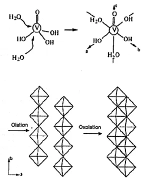
20 > V20s orthorhombicEquation 2-3 The final sol-gel structure consists of ribbon-like polymeric species with
dimensions of approximately 100 x 10 x 1 nm. The acidification route from sodium metavanadate involves an ion exchange step, which increases in viscosity over time. The formation of the ribbon V205 network stems from the condensation of V-OH groups of
the hexacoordinated species [VO(OH)3(OH2)2]0.[32] Two reactions govern the final
structure (Figure 2-3), fast olation reactions along the HO-V-OH2 (y-axis) direction and
slower oxolation reactions along the HO-V-OH direction (x-axis), with a double bonded O along the z-axis (where condensation will not occur). Increasing the amount of water favors M - OH groups over M -0 - M groups.[34] The polarity and viscosity of the
H2) 20 OH OOil
O)) a
J
H 110
Olation Oxolation
Figure 2-3: Formation of V205 from sol gel process a) coordination expansion b)
condensation. Reproduced from Livage. [36]
The surface area of the final sol-gel vanadium oxide can be controlled by altering the way the solvent phase is removed, through techniques including supercritical
drying[37], freeze-drying[38], or solvent exchange.[39, 40] This variation in surface area arises due to the surface tension forces that develop at the interface between the
evaporating liquid phase and the gas phase. When deposited onto a flat substrate and
dried in air, vanadium pentoxide gels give rise to xerogel layers that exhibit a preferred
orientation, a surface area of 10 m2/g, and particle size between 4 - 40 pm. Large
capillary forces exerted on the gel structure at the liquid-gas interface collapse the porous structure during the pore fluid's evaporation in air. Intercalation of ions occurs readily at room temperature within a few minutes when the gel is dipped into an aqueous solution of ionic salts. This addition does not destroy the internal structure of the oxide network or the one-dimensional stacking of the V205 ribbons.
Aerogels, created by supercritical drying processes, possess highly
interconnected, bicontinuous structures of solid phase and pores. Supercritical drying replaces the solvent with a gas under conditions that prevent pores from collapsing via
capillary forces. The liquid is removed above the critical point where there is no surface tension. The first aerogels, formed by Hirashima et al. from VO(OEt)3supercritical
drying of ethanol at 255"C at 210 atm, were crystallized.[42] The use of supercritical CO2
to form aerogels was developed by Chaput et al. with VO(OPr')3 in acetone.[37] The
thickness of the solid phase surrounding the pores is in the range of 10-30 nm, with a high surface area of 450 m2/g. The porous structure allows certain electrolytes to penetrate within the aerogel particles and the material's thin solid phase reduces the length of ionic diffusion paths for the intercalated ions.[43-45] The characteristic mesoporosity of these materials provides both molecular accessibility and rapid mass transport via diffusion.[46]
Another approach towards an aerogel-like material, termed an ambigel, consists of a sequence of solvent exchange steps in which the new solution is miscible with the previous one and its surface tension is lower than the previous one. For example, exchanging water with acetone and then hexane, leads to an organogel that, when dried by evaporation below the critical point, generates a material with a surface area of 200 m2/g. [39, 40]
Other nanoscale microstructures for vanadium oxide to increase capacity and rate capability have included nanotubes, nanorolls and nanowires. Wang et al. have reviewed the properties of nanostructured vanadium oxides including nanotubes, nanorolls, nanoarrays and nanobelts.[47] Singhal et al. have seen increased capacity in partially crystalline nanoparticles of vanadium oxide produced using the combustion flame-chemical vapor condensation process.[48] Further background on these nano-architectured vanadium oxides will be presented in the next section.
Electrochemistry of Vanadium Oxide
The overall reaction for the insertion of lithium into vanadium oxide particles is: yLi+ ± LixV205 + ye~ + Lix+yV205
Equation 2-4 or with the valence state of vanadium taken into consideration this equation becomes (where x and y are the fractions of Li, V4* and V5+ valence upon lithation):
yLi* + Lix[(2-x)V5*, xV4*]O5 + ye - Lix+y[(2-x-y)V5*, (x+y)V4*]O5