Publisher’s version / Version de l'éditeur:
Technical Note (National Research Council of Canada. Division of Building Research), 1968-09-01
READ THESE TERMS AND CONDITIONS CAREFULLY BEFORE USING THIS WEBSITE.
https://nrc-publications.canada.ca/eng/copyright
Vous avez des questions? Nous pouvons vous aider. Pour communiquer directement avec un auteur, consultez la première page de la revue dans laquelle son article a été publié afin de trouver ses coordonnées. Si vous n’arrivez pas à les repérer, communiquez avec nous à PublicationsArchive-ArchivesPublications@nrc-cnrc.gc.ca.
Questions? Contact the NRC Publications Archive team at
PublicationsArchive-ArchivesPublications@nrc-cnrc.gc.ca. If you wish to email the authors directly, please see the first page of the publication for their contact information.
NRC Publications Archive
Archives des publications du CNRC
For the publisher’s version, please access the DOI link below./ Pour consulter la version de l’éditeur, utilisez le lien DOI ci-dessous.
https://doi.org/10.4224/20359031
Access and use of this website and the material on it are subject to the Terms and Conditions set forth at
Air Leakage Characteristics of Some Brick and Concrete Block Walls
Sasaki, J. R.
https://publications-cnrc.canada.ca/fra/droits
L’accès à ce site Web et l’utilisation de son contenu sont assujettis aux conditions présentées dans le site LISEZ CES CONDITIONS ATTENTIVEMENT AVANT D’UTILISER CE SITE WEB.
NRC Publications Record / Notice d'Archives des publications de CNRC: https://nrc-publications.canada.ca/eng/view/object/?id=30bf5c5f-498d-4ac0-9953-fd3f6ddb09fb https://publications-cnrc.canada.ca/fra/voir/objet/?id=30bf5c5f-498d-4ac0-9953-fd3f6ddb09fb
DIVISION OF BUILDING RESEARCH
No.
NATIONAL RESEARCH COUNCIL OF CANADA
NOTJE
525
'1'
ECIHI N lCAIL
PREPARED BY J. R. Sasaki CHECKED BY A.G.W. APPROVED
BY N. B. H.
DATESeptember 1968
PREPARED FOR Information and inquiry
SUBJECT AIR LEAKAGE CHARACTERISTICS OF SOME BRICK AND CONCRETE BLOCK WALLS.
This report presents the air leakage characteristics obtained
from measurements of nine brick and concrete block walls in the DBR/NRC
test huts at Ottawa and Saskatoon. The leakage characteristics of the first
three walls were obtained in the Saskatoon test huts; the remainder were
obtained in the Ottawa huts. All the test huts had an overall plan area of
approximately 6 ft by 6 ft.
The study was undertaken to compare the leaka,ge characteristics
of different types of walls as constructed in the field; and to determine
the reduction in leakage effected by fill-insulation and different surface finishes.
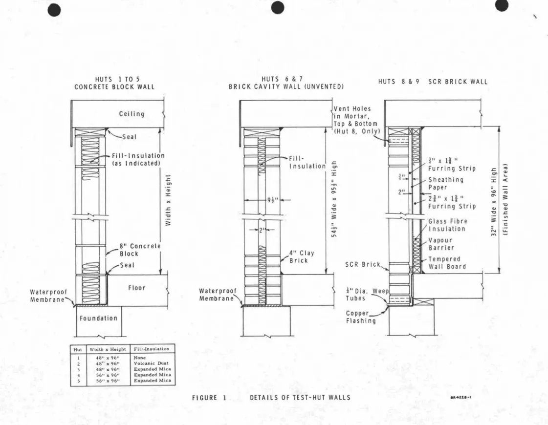
DESCRIPTION OF TEST-HUT WALLS
Details of the nine test-hut walls are shown in Figure 1.
Wall No.1. - Light-weight concrete block.
The blocks (expanded clay aggregate) were 8 by 8 by 16 in.
and had two hollow cores. The wall had no fill insulation. The mortar
used in the wall was 1 part lime, 1 part cement and 5 parts sand (by
volume). The total inside area of the four walls in the hut was 128 sq ft.
Air leakage tests were performed with the wall surfaces (a;)
unfinished (b) with two coats of latex paint added on the inside
TABLE I
WALL AIR LEAKAGE CHARACTERISTICS Cu Ft of Air/fIr){Sq Ft of Wall Area)
(Average of 4 Walls)
Hw - in. of water (A) CONCRETE BLOCK WALLS
.20 .30 .40 .05 • 10 • 15
No. 1
-
lゥセエ -weight concrete block wall (no insulation)- are surfaces 20 40
-two coats of paint added on inside surface 8 13 17 21 29 37
-two coats of stucco and one coat of paint
added on outside surface 4 8 11 14 19 24
No. 2
-
Light-weight concrete block wall- with no insulation 17 34
- with fill-insulation (volcanic dust) 14 25 35 45
No. 3 Light-weight concrete block wall, with
fill-insulation (expanded mica) 12 23 34 46
No. 4
-
Light-weight concrete block wall, withfill-insulation (expanded mica) 11 21 30 39 55 71
- three coats of stucco added on outside
surface 7 13 18 22 30 36
No. 5 - Concrete block wall, with fill-insulation
(expanded mica) 2 4 6 8 11 14
- one coat of paint added on inside surface 2 4 6 7 10 12
(B) BRICK WALLS
ASHRAE Values
-
13"Solid brick, bar e 5 8 11 14 20 24-
8t" Solid brick, bare 5 9 13 16 24. 28-
8i"
Solid brick, two coats ofplaster added on inside lIurface .08 A 14 .20 .27
No. 6
-
Clay-brick cavity wall (unvented), withfill-insulation (expanded mica) 2 4 6 7 9 11
- three coats of plaster added on inside
surface .5 1.0 1.6 2.2
No. 7 Clay-brick cavity wall (unvented) with
fill-insulation (granulated mineral wool) 2 4 6 7 9 11
- three coats of plaster added on inside surface 1 2 3 4 No. 8 SCR brick wall with interior finish, vented
air space 1.5 3 4 5 7 8
No. 9 - SCR brick wall with interior finish, unvented
2
-of cem.ent -base stucco and one coat -of cement paint on the outside wall surface.
Wall No.2 Light -weight concrete block.
The concrete blocks, rhortar and wall area were
identical to wall No.1. The inside and outside wall
sur-faces were unfinished.
Air leakage tests were performed (a) with and (b) without fill-insulation (volcanic dust) in the hollow blocks.
Wall No.3 Light -weight concr ete block.
This wall was identical to wall No. 2 except the fill-insulation was expanded mica.
Wall No.4 Light -weight concrete block.
The blocks (expanded slag aggregate) were 8 by 8
by 16 in. and had three hollow cores which were filled with
expanded mica insulation. The mortar used in the wall was
1 part lime, 1 part cement and 5 parts sand (by volume).
The total inside wall area was 150 sq ft.
Air leakage tests were performed (a) with the wall sur-faces unfinished, and (b) with three coats of stucco added on the outside wall surface.
Wall No.5 Concrete block.
The blocks (sand and gravel aggregate) were 8 by 8 by
16 in. and had three hollow cores which were filled with
ex-panded mica insulation. The m.ortar and wall area were
identical to wall No. ' 4.
Air leakage tests were performed (a) with the wall sur-faces unfinished, and (b) with one coat of latex paint added On the inside wall surface.
3
-The wall consisted of two wythe s of clay brick, 2 3/8 by 3 3/4 by 8 in., separated by a 2-in. unvented cavity which
was filled with expanded :mica insulation. The :mortar was 1
part li:me, 1 part ce:ment and 5 parts sand (by volu:me). The
total inside wall area was 146 sq ft.
Air leakage tests were perfor:med with the wall sur-faces unfinished, and with three coats of plaster added on the inside wall surface.
Wall No.7 - Brick cavity-wall.
This wall was identical to wall No. 6 except that the fill-insulation was granulated :mineral wool; the sa:me tests were perfor:med.
Wall No.8 - SCR brick.
The wall consisted of a single wythe of SCR brick,
2 1/6 by 5i by 11 i in., finished on the inside with the
following: 3/4 by 1 5/8 in. furring strips; sheathing paper;
2 3/8 by 1 5/8 in. furring strips; vapour barrier; and te:mpered
wallboard. Glass fibre insulation filled the space between
sheathing paper and vapour barrier. The air space between
sheathing paper and brick was vented to the outside. A li:me
:mortar consisting of 1 part li:me to 3 parts sand (by volu:me)
was used in the brickwork. The total inside area of the finished
wall was 128 sq ft.
Wall No. 9 - SCRbrick.
This wall was identical to wall No. 8 except that the air space between brick and sheathing paper was not vented. AIR LEAKAGE TEST PROCEDURE AND RESULTS
To ensure air leakage through the walls alone, all the other leakage sources in the test hut were sealed; these extraneous leakage sources were the ceiling, the floor, and the Joints between walls, ceiling and floor.
4
-test hut with metered air and obtaining the air flow through the four
walls at a number of values of H , the difference between the air
w
pressure inside the hut and that outside. At each value of H , the
w
total air flow in cubic feet of air per hour was divided by the total inside wall area to give the leakage rate in cubic feet of air per hour per square foot of wall area.
The conditions of test and the air leakage characteristics for the nine walls are given in Table I; the characteristics are shown in Figur e 2.
Included in the figure and table for comparison purposes are the characteristics for the following walls: a solid 13-in. brick wall, unfinished surfaces; a solid 8 1/2-in. brick wall, unfinished surfaces; and a solid 8 1/2-in. brick wall with two coats of plaster
on the inside surface. These walls were of poor workmanship, and
were constructed with porous bricks and lime mortar. The
charac-teristics were obtained from the Amedcan Society of Heating, Re..;. frigerating and Air-Conditioning Engineers (ASHRAE) Handbook of
Fundamentals, 1967, (Chapter 25, ーNTQPIセ
The leakage through the light-weight concrete block walls
was much higher than the leakage through the other walls.
Fill-insulation reduced the leakage by 25 per cent, but the leakage through the insulated light-weight walls was still 5 times greater than that through the dense concrete block wall.
Surface treatment of the light-weight blocks effected a greater
reduction in leakage than fill-insulation. The leakage through wall
No.1 with surface treatment on inside and outside was 1/5 that through the bare wall and only twice that through the dense concrete
5
-block wall; it was comparable to the leakage through a solid wall of porous brick.
The leakage through the dense ,concrete block wall was of the same order of magnitude as the leakage through the clay brick and SCR brick walls, and was half that through a solid wall of porous
brick. A coat of paint on the inner surface of the concrete block had
little effect on the leakage.
The leakage through the bare clay brick walls was higher than that through the SCR brick walls; however, interior plastering
reduced it below that of the SCR walls. None of the tested walls
had a leakage characteristic as low as that given in the ASHRAE Handbook for brick walls with interior plastering.
The leakage characteristics determined from the present study are useful in indicating the relative tightness of the differeht
wall types and wall finishes. These characteristics, however,
should be used with caution in predicting the field performance of
actual walls, since the workmanship involved in the construction df
the test huts was probably better than that found in normal field construction.
e
e
e
"
HUTS I TO 5
CONCRETE BLOCK WALL
HUTS 6 & 7
BRICK CAVITY WALL (UNVENTEDI HUTS 8 & 9 SCR BRICK WALL
Fou ndation セB
x Ii "
Furring Strip .r:;1 セ C7' Q> Sheathing .-::I: <セ Paper -0'"
2i"xIi"
a- セ x Furring Strip "0 Q> Q> "0 .r:; .- v> ·Glass Fibre セ .-c Insulation N ... '"" Vapo u r Barrier Tempered Wall Board Copper Flashing セ '" LI'\ a-x Q> "0 """"'<t LI'\ Fi 11- I I nsulation セ ::I: r---9i" t--- 2 If--4" Clay Bric k Vent Holes in Mortar,i
セr
tTOP & Bottom (Hut 8, Only) Waterproof Membrane" x セ .r:; -"0 .r:; C7' Q> ::I: Floor 8" Concrete Block Sea I Cei Ii ng F---.J.-toooFill-lnsulation (as I ndicatedl I...--:::::::;---セ
' -Sea I Waterproof MembraneHut Width x Height FilJ -Insulation
1 48" x 96" None
2 48" x 96" Volcanic Dust
3 48"x96" Expanded Mica
4 56" x 96" Expanded Mica
5 56" x 96" Expanded Mica
•
e
e
\,
5 45 10 20 15 25 35 40 30 0.3 BRICK WALLS O. 2 IN. OF WATER'119
セ SiEIl£:O INSIO£: I f<LL 7 \PLf<'II Wf<LL 6 lPLf<STEREO INSIDE)
NセB S0f+P-BRICK- PLf<STEREO INSIDE If<SHRA§
I i= I 0 O. 4 Hw· O. 1 / / , / / セBGO
",
- / KセO ...セケG ....セNLO \\>c,/ HLセ / ' \<:.'+-./" \Q^セGO セ\Q^セ[O ,..\<;) / ' •.,0'/';/
• .,0,/ |セNO セBO , / /' , / / / / , / ,// / 'セセO
セOGヲセ
All Walls Except ASHRAE Walls Are Insulated
8
BLOCK WALLS \..'> Giャセセ ----Ot\ ...--.1'\5'"to \ 1>\1'\i 0;IV '!oI1>1.1.All Wall Faces Unfinished Unless Noted
• Denotes Uni n su lated Walls; all Others Are
Insulated 0.2 0.3 0 Hw. IN. OF WATER O. 1