HAL Id: hal-01347065
https://hal.archives-ouvertes.fr/hal-01347065
Submitted on 19 Dec 2016
HAL is a multi-disciplinary open access
archive for the deposit and dissemination of sci-entific research documents, whether they are pub-lished or not. The documents may come from teaching and research institutions in France or abroad, or from public or private research centers.
L’archive ouverte pluridisciplinaire HAL, est destinée au dépôt et à la diffusion de documents scientifiques de niveau recherche, publiés ou non, émanant des établissements d’enseignement et de recherche français ou étrangers, des laboratoires publics ou privés.
and Its Impact on Electronic Transport
Benoit Mahler, Loic Guillemot, Léo Bossard-Giannesini, Sandrine Ithurria,
Debora Pierucci, Abdelkarim Ouerghi, Gilles Patriarche, Rabah Benbalagh,
Emmanuelle Lacaze, François Rochet, et al.
To cite this version:
Benoit Mahler, Loic Guillemot, Léo Bossard-Giannesini, Sandrine Ithurria, Debora Pierucci, et al.. Metallic Functionalization of CdSe 2D Nanoplatelets and Its Impact on Electronic Trans-port. Journal of Physical Chemistry C, American Chemical Society, 2016, 120 (23), pp.12351-12361. �10.1021/acs.jpcc.6b02101�. �hal-01347065�
Metallic Functionalization of CdSe 2D Nanoplatelets and its Impact on Electronic Transport
Benoit Mahler
1, Loic Guillemot
2, Léo Bossard-Giannesini
2, Sandrine Ithurria
3, Debora
Pierucci
4, Abdelkarim Ouerghi
4, Gilles Patriarche
4, Rabah Benbalagh
5, Emmanuelle Lacaze
2,
François Rochet
5*, Emmanuel Lhuillier
2*1
Institut Lumière-Matière, CNRS UMR 5306, Université Lyon 1, Université de Lyon, 69622
Villeurbanne CEDEX, France.
2
Institut des Nanosciences de Paris, UPMC-CNRS UMR 7588, 4 place Jussieu, boîte courrier
840, 75252 Paris cedex 05, France.
3
Laboratoire de Physique et d’Étude des Matériaux, PSL Research University, CNRS UMR
8213, Sorbonne Universités UPMC Univ Paris 06, ESPCI ParisTech, 10 rue Vauquelin, 75005
Paris, France.
4
Laboratoire de Photonique et de Nanostructures, LPN/UPR20—CNRS Route de Nozay,
91460 Marcoussis, France.
5
Sorbonne Universités, UPMC Univ Paris 06, UMR 7614, Laboratoire de Chimie Physique -
Matière et Rayonnement, 11 rue Pierre et Marie Curie, 75231 Paris Cedex 05, France.
ABSTRACT: We explore the gold functionalization of 2D CdSe nanoplatelets (NPL) as a possible
way to tune their electronic and transport properties. We demonstrate that the size and
location of the gold tip can be controlled using light and temperature. The Au tip-CdSe NPL
hybrid present a large rise of the conductance compared to the pristine semiconductor (i.e.
without gold functionalization). The role of the semiconductor in this transport remains
unclear and needs to be better understood. We hypothesize four mechanisms: (i) a reduction
of the band gap energy due to the formation of a gold-selenium compound, (ii) a charge
transfer between the metal and the semiconductor leading to an increase in carrier
concentration and (iii) a change in the inter nanoparticle tunnel barrier height or (iv) a simple
percolation process between the metallic grain. X-ray photoelectron spectroscopy (XPS)
shows that the CdSe NPL are unaffected by oxidation, and that gold is in the metallic state Au
0.
We consequently exclude the formation of a narrow band gap Au
2Se phase as the possible
mechanism leading to the observed rise of conductance. Moreover Kelvin Probe force
microscopy and XPS gives evidence for an increase in work function upon gold-tipping, which
can be interpreted in terms of a shift of the Fermi level toward the valence band maximum.
As hole-conduction in CdSe NPLs is very unlikely to occur, we rather favor the hypothesis that
the strong increase in conduction is largely driven by percolation between the metallic tips as
the main mechanism responsible for transport in this hybrid system.
1. INTRODUCTION
While the growth of colloidal nanocrystals gets more mature, the possibility to synthetize complex systems in solution become real. In addition to semiconductor heterostructures,1 one can cite Janus2
nanoparticles and metal tipped semiconductors.3,4,5 The latter are of utmost interest for transport and
photocatalysis. In particular such hybrid materials present enhanced conduction3 and photoconduction6 properties resulting from their modified electronic structures4. Moreover, metal-semiconductor hybrids7 are well suited for photocatalysis, to ensure the splitting of the
photogenerated electron-hole pairs.
Gold tipped semiconductor synthesis generally relies on the reduction of a gold salt in presence of semiconductor nanocrystals and a reducing agent, generally an amine. So far most of the efforts have been focused on 1D rod functionalization.3,8,9 On metal-functionalized nanorods, it was demonstrated
that the electronic impact of the metal on the semiconductor remains limited to a few nanometers in the vicinity of the metal.4 As a result, only a limited part of the material behaves as a hybrid structure. In this paper, we investigate the growth of gold-tipped cadmium chalcogenides 2D nanoplatelets10,11,12
(NPLs). With the 2D geometry of the NPL we can achieve more tips per nanocrystal than for nanorods (or in other words a higher metal-to-semiconductor ratio) and possibly obtain a stronger coupling between the metal and the semiconductor. The metal functionalization of cadmium chalcogenides NPLs have been recently proposed using gold13,14, palladium14, platinum14,15and nickel.16 Here, we
demonstrate that by switching from metal reduction to photo-assisted metal reduction and cation exchange it is possible to obtain size and site control of the metal functionalization, which was not previously achieved. Moreover we expand the method and evidence that not only CdSe NPLs but also their heterostructures (CdSe/CdZnS core/shell geometries) can be functionalized by metals thanks to the proposed procedure.
We also focus on the transport properties of this hybrid system. As expected, we observe a significant boost of the conductance in presence of the gold functionalization. This result is consistent with previous transport measurements on such metal-semiconductor hybrid systems either conducted on single nanoparticle3 or on an array of nanoparticles.6,17 The origin of this increase of conductance remains mostly unknown. Several explanations have been proposed, including a decrease of the Schottky barrier height3 and percolation between metal domains18. In particular, the role of the semiconductor remains unclear. We speculate four mechanisms involving the semiconductor to
explain the observed rise of conductance: (i) an increase of the semiconductor carrier density due to a reduction of the semiconductor band gap energy induced by the formation of a narrower band gap phase containing a gold chalcogenide. (ii) An increase of the semiconductor carrier density resulting from a charge transfer process, or (iii) a stronger coupling between NPLs due to a possible lowering of the inter-NPL tunnel barrier. Alternatively the semiconductor may not be involved in the conduction mechanism and the transport only results from a percolation process between the metallic sites. To discriminate between these different scenarios, we use X-ray photoemission spectroscopy (XPS) and Kelvin probe force microscopy (KPFM). These two techniques allow us to precisely study the chemical and electronic structure of the Au tip-CdSe NPL hybrid nanomaterial.
2. Methods
2.1. Chemicals
inorganic precursors
Selenium powder (Sigma-Aldrich, 99.99%), Cadmium nitrate tetrahydrate (Cd(NO3)2(H2O)4, Aldrich 99,999%), Cadmium acetate dihydrate (Cd(OAc)2(H2O)2, Aldrich 98%), thioacetamide (TAA, Aldrich, 99%), Zinc nitrate hexahydrate (Zn (NO3)2(H2O)6, Aldrich 99%), Gold chloride (AuCl3, Strem Chemicals).
Solvents
n-Hexane (VWR, 98%), Ethanol (EtOH Carlo Erba, 99.5%), Isopropanol (VWR,100%), Toluene (VWR, 99.8%), Chloroform (VWR, normapur), 1-Octadecene (ODE, Aldrich, 90%).
Organic Ligands
Oleic acid (Aldrich, 90%), Octylamine (Aldrich, 99%), Myristic acid (Sigma-Aldrich, 95%), Dodecylamine (DDA, Aldrich, 98%), Didodecyldimethylammonium bromide (DDAB, Aldrich, 98%), Ethanedithiol (EDT, Aldrich 98%).
2.2. Nanoparticle synthesis
CdSe nanoplatelets synthesis with a first excitonic feature at 510 nm
The CdSe nanoplatelets are synthetized according to a method previously described.10 Briefly, 960 mg of Cd(OAc)2(H2O)2, 2.36 g of oleic acid and 90 mL of ODE are degased under vacuum at 100°C for 1 h. Then 144 mg of Se is added and the mixtre is heated to 240 °C under Argon for 15 min. At 180°C, 360 mg of Cd(OAc)2(H2O)2 are quickly added. The reaction is stopped by removing the heating mantle and 5 ml of oleic acid is injected. Nanoplatelets are then separated from spherical quantum dots by selective precipitation and suspended in 10 mL of hexanes.
The typical obtained material is made of NPLs which are 1.2 nm thick and with a rectangular shape (10 nm x 40 nm), see Figure 1a. The material shows a first exciton at 510 nm, see Figure 1e and S1.
Growth of a Cd
0.5Zn
0.5S shell
The protocol is adapted from ref 19: 10 mL of CdSe NPLs in hexane are mixed with 25 mL of CHCl3, 300 mg of thioacetamide (TAA) and 3 mL of octylamine and sonicated until complete dissolution of the TAA. 1 mL of Zn(NO3)2 0.2 M in EtOH and 1 mL of Cd(NO3)2 0.2 M in EtOH are added and the mixture is heated to 60 C for 4 h. The nanoplatelets are then precipitated with isopropanol and dispersed in toluene. Their typical thickness is around 5 nm, while their lateral extension is almost unchanged compared to the CdSe NPLs core (12 nm x 40 nm).
2.3. Gold functionalization
Gold reduction producing small metallic tips
To add the gold tip to the CdSe NPLs, we developed a procedure which is inspired from the one developed for the gold tipped rods.3,8 Typically, 36 mg of AuCl
3, 120 mg of didodecyldimethylammonium bromide (DDAB) and 210 mg of dodecylamine (DDA) are mixed in 10 mL toluene. The obtained yellow orange solution is called A. This solution is not stable over a long time and need to be freshly prepared.
In a 50 mL three neck flask, 1 mL of a NPLs solution with an optical density of 20 (at the first excitonic peak) is mixed with 4 mL of toluene under Argon atmosphere. 0.1 mL of A is mixed with 3.2 mL of toluene and then injected in the flask dropwise over 5 minutes. The solution turns from yellow to a light brown orange. The final mixture is precipitated by addition of ethanol and centrifuged. The supernatant is discarded and the solid is dispersed again in toluene. This purification step is repeated a second time. Final storage is done in toluene. With this method, the gold functionalization is located on the edges of the NPL –preferentially at the corner. NPLs present between 1 to 4 gold beads, which size remains small (2 to 5 nm), see Figure 1b. With such a functionalization the NPLs formed a weakly connected network, where the gold beads act as crosslinker agent, see Figure 1a.
Gold photoreduction producing large metallic tips
The synthesis is adapted from Menagen et al.5 with minor modifications. Typically, in a 20 mL vial, 12 mg of AuCl3, 30 mg of DDA, 19 mg of DDAB and 4.5 mL of toluene are mixed and sonicated for 2 min. The mixture is then added to 250 μL of nanoplatelets (CdSe/Cd0.5Zn0.5S) with a Zn rich surface and a
concentration of ≈ 5 µM, dispersed in 2.5 mL of toluene. The vial is then put in an ice bath in front of a 150 W Xenon lamp and the light is focused on it for 4 h.
While switching from dark reduction to photon assisted gold reduction we observe an increase of the gold tips size from below 5 nm to the 10-20 nm range. 20% of the CdSe NPLs present no tip, 60% present a single tip and 20% have 2 tips and more. Generally the NPLs present only one gold tip located at one of the corners, see Figure 2.
Gold thermal cation exchange
The synthesis is exactly the same as the one described above for the Au photoreduction, but S rich NPLs are used and the reaction is conducted under dark condition at ≈70°C. Using this condition the gold functionalization is rather located in the center of the NPL, see TEM images in Figure 3.
2.4. Material characterization
UV-Visible absorption spectra are measured using a Cary 5E spectrometer.
Samples for X-ray diffraction, are prepared by dropcasting the nanoparticle solution on a Si wafer to form a 1 cm x 1 cm film. The X-ray diffraction acquisition is conducted using a Philips X’pert system using the Cu Kα line (λ=0.154 nm) as photon source. The diffractometer is operated under 40 kV and 40 mA.
Transmission electron microscopy (TEM) was obtained by dropcasting the nanoparticle solution onto a copper TEM grid. Grids were degased overnight under secondary vacuum before imaging. Non high-resolution imaging was obtained on a JEOL 2010 microscope, while a JEOL JEM 2200FS, with a Cs aberration corrector was used to obtained high resolution image in STEM HAADF mode. Nanometer resolved energy dispersive X-ray spectroscopy (EDX-EDS) was also conducted on this microscope. For ensemble EDX analysis we use an Oxford EDX photon probe on a FEI Magellan scanning electron microscope (SEM). The typical operating condition for the SEM relies on 15 kV electron acceleration operated with a 1.6 nA current.
We used the X-Ray Photoelectron Spectroscopy (XPS) setup located at the Laboratoire de Chimie Physique Matière et Rayonnement (UPMC). The measurements were carried out in UHV conditions (P=3x10⁻¹⁰ mbar) using a non-monochromatized Mg K
α source (the main Kα1,2 line energy is 1253.6 eV, and its full-width at half maximum is 0.75 eV) and a SPECS PHOIBOS150 hemispherical electron analyzer (radius of 150 mm). We used a pass-energy of 50 V and an entrance slit of 3 mm. The overall energy resolution (source plus analyzer) was 0.90 eV. For the XPS analysis, the nanoplatelets solution
was dropcasted on a cleaned Si wafer. Once the film was dried, it was dipped into a 0.5% in volume solution of ethanedithiol in ethanol for 30 s. Then the film is rinsed in pure ethanol before being dried again. The deposition process is repeated several times until a roughly 100 nm thick film is formed. Two types of films were produced, one with CdSe nanoplatelets decorated with Au nano-tips (termed “Au tip-CdSe NPL”), and one with plain CdSe platelets (lacking Au nano-tips, and termed “CdSe NPL”). Due to the resistivity of the films, charging effects were observed. This issue was solved by biasing the Si wafer positively to attract more stray electrons. The binding energy (with respect to the Fermi level) was determined after deposition of an “electrically floating” macroscopic gold disk on top of the layer (with a known Au 4f7/2 binding energy of 84.00 eV). A detailed description of the discharging procedure is given in the Supporting Information. The accurate measurement of the Au 4f7/2 binding energy is carried out in this setup, after a careful measurement of the Fermi edge position using a freshly ion sputtered gold lamella.
Kelvin probe force microscopy (KPFM) was carried out using a Bruker multimode system. A Pt tip of radius 20 nm is used as a conductive probe. The nanoparticles are dropcasted on a freshly cleaved MoS2 wafer, of known work function (4.8 eV). To achieve a smooth single layer coating of the substrate the nanoparticles are used as such (i.e. without ligand exchange).
2.5. Transport measurements
Electrodes preparation
We prepare interdigitated electrodes using standard lithography method. The electrodes include 25 pairs of 2.5 mm long electrodes. Each of the digits is spaced by 10 µm from its neighbor. Electrodes are deposited on a Si/SiO2 wafer (400 nm oxide) and are made of 3 nm Cr covered by 35 nm gold.
Ligand exchange for transport
For transport, we perform a ligand exchange on film. Briefly we prepare a solution of ethandithiol at 0.5% in volume in ethanol. The nanoparticles, dispersed in hexane, are dropcasted on the electrodes and the film is dried. The film is then dipped for 3 min in the EDT solution, rinse in pure ethanol and finally dried under nitrogen flow. The deposition process and the subsequent ligand exchange are repeated two other times. The final film thickness is around 50nm. Electrical measurements are acquired with a keithley 2400 source-meter.
3.1. Synthesis and optical properties
Similarly to the case of nanorods, we have prepared gold-tipped nanoplatelets by reduction of a gold salt in presence of amine and long ammonium ligands. This procedure leads to the formation of metallic tips preferentially located on the corners of the CdSe NPLs. Under ambient conditions—room temperature and no excess light—the gold tips remain small in size (2-5 nm, see the Figure 1a-b). This size is typically smaller than the one reported by Naskar et al14 who conducted the Au tip growth in
absence of ammonium ligands. The hybrid Au tip-CdSe NPLs tend to bridge between each other and form a network, see Figure 1a, as previously observed for rods.17
Figure 1 a. TEM image of Au tip-CdSe NPLs. The inset is a zoom on the Au tip. b. TEM image of Au tip-CdSe NPLs. The highlighted areas have been probed using EDX and the Cd, Se and Au content is given in Table 1. c. X-Ray diffractogram of CdSe NPLs and once functionalized with the gold tip. d. Ensemble energy dispersive X-ray spectroscopy of CdSe NPLs functionalized with Au tips. e. Absorption spectra for a series of CdSe core NPLs functionalized by Au nanoparticles at their tip for different level of gold introduced. The volume corresponds to the volume of solution A (see experimental section) introduced in the CdSe flask.
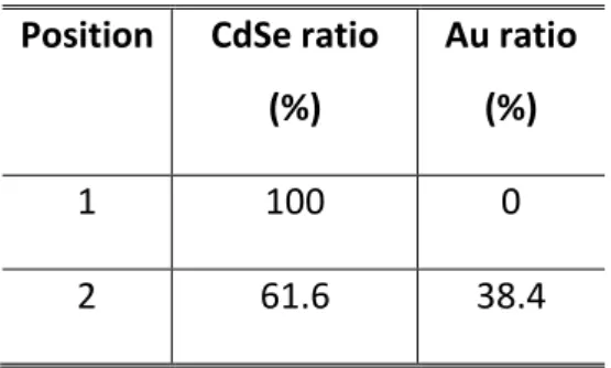
X-ray diffraction (XRD) confirms the formation of a metallic gold crystalline phase, as shown by the diffraction peak at 2θ≈38° ((111) peak of Au), see Figure 1c. Moreover the CdSe diffraction pattern remains unaffected. Energy dispersive X-ray spectroscopy (EDX), see Figure 1d, further confirms the presence of gold. The amount of gold is estimated to be around 8% of the CdSe molar content in this Au tip-CdSe NPL hybrid system. From this amount we can estimate the reaction yield of the gold reduction to be around 20%, see the supporting information for details. Using EDX coupled with TEM we check that the gold is only located around the tip and does not form a thin layer over the semiconductor, see Table 1 and Figure 1b.
Table 1 Molar ratio of CdSe and Au obtained from energy dispersive X-ray spectroscopy on the
site shown on Figure 1b.
Position
CdSe ratio
(%)
Au ratio
(%)
1
100
0
2
61.6
38.4
When the amount of gold increases, the absorption spectrum of the NPLs tends to broaden but the excitonic signal remains visible even at high gold concentration, see Figure 1e. Such an absorption spectrum typically results from the sum of the excitonic component of the nanoplatelets and the plasmonic feature of the gold.20 It is worth noting that the photoluminescence signal from the CdSe
NPLs disappeared quickly after the gold introduction. This drop results from the exciton energy transfer (i.e. both the electron and hole are transferred) from the exited state of the semiconductor to the metal,21,22 due to the spectral overlap of the NPLs photoluminescence and the gold absorption. This
energy is then dissipated as thermal losses in the metal.
This first synthesis based on spontaneous gold reduction at room temperature by the amines is not suitable to achieve large gold tips. Indeed this method leads to big unconnected gold nanoparticles when a large amount of gold is introduced. To further increase the size of the metallic tips, we have conducted the synthesis through a photoreduction process under strong illumination (150 W Xenon lamp). In this case, larger (10-20 nm) metallic tips are formed at the edges of the NPLs, see Figure 2a. As for gold reduction operated under dark conditions, the absorption spectrum is a sum of the excitonic contribution and the plasmonic contribution (see Figure 2b).
Figure 2 a. TEM image of CdSe/CdZnS nanoplatelets functionalized using gold photoreduction. b. Absorption spectra of raw CdSe/CdZnS NPLs and of the same material once functionalized using the gold photoreduction.
So far, all the metallic functionalization reported on 2D nanocrystals were located on the nanocrystal edges13-16. In the two previously described procedures, the metallic tips growth is conducted at room temperature. If a similar metal functionalization is conducted at higher temperature we rather favor a cation exchange process.23,24 This exchange has been demonstrated on chalcogenides nanocrystals
using small cations such as Cu+ and Ag+ ions, 25 but it can also occur with relatively less studied gold ions.24,26 For cation exchange on 2D NPLs it was demonstrated that there is a minimum thickness of the latter ones to preserve the 2D shape.27 As a consequence, we use core-shell structures19 (CdSe/CdZnS) in the following because of their larger thickness. It is also worth noticing that the gold reduction previously described not only works with purely CdSe core NPLs, but also with heterostructured (CdSe/CdZnS) nanocrystals, see Figure 2 and figure S2.
Figure 3 a. TEM image of the obtained heterostructures after thermal cation exchange with Au on CdSe/CdZnS NPLs. b. X-Ray diffractogram of the same material, revealing an Au/Au2S composition. c. Absorption spectra of CdSe/CdZnS NPLs and of the heterostructures obtained after Au thermal cation exchange.
Once gold cation exchange is achieved, we observe a different gold functionalization compared to the previous processes, for which the metal tips is external to the semiconductor NPLs. Here, after cation exchange, the metal site is not forming an edge tip and is rather located in the center of the main facet of the NPL, see Figure 3a. The cation exchange is confirmed by XRD, evidencing the appearance of an Au2S phase28, as highlighted by the diffraction peak at 2θ≈31°((111) peak of Au2S), see Figure 3b. The metallic nature of the center of the hybrid nanoparticle is in the same time evidenced by the diffraction peak at 2θ≈38° ((111) peak of Au), relative to Au° phase. Moreover the diffraction peaks relative to the initial CdSe/CdZnS NPLs have disappeared, which indicates that most of the cations have been exchanged to form a gold chalcogenide phase. The optical absorption further confirmed the successful cation exchange, since we no longer observe the excitonic peak relative to the CdSe/CdZnS NPLs, see Figure 3c. On the other hand, the absorption edge is strongly redshifted according to the narrow band gap semiconductor nature of Au2S.
Even though the formation of the Au2S phase can appear as detrimental for catalytic application it serves to underline that a cation exchange mechanism may compete with direct metal reduction. This change in the material composition needs to be considered while discussing the transport in such semiconductor-metal networks.
3.2. Electronic transport
In the following we choose to investigate the transport properties of the Au tip-CdSe NPLs29,30 hybrid
systems (based on CdSe core only) and to focus on the material obtained thanks to the gold reduction in the dark leading to small Au tips on the NPLs edges.
In the absence of gold and in spite of ligand exchange toward short capping ligands, aiming at reducing the inter-NPL distance and thus increasing the film mobility, the CdSe NPLs network is poorly conductive, see Figure 4. This effect results from the wide band gap nature of CdSe, which, in absence of gating31,32 leads to a complete lack of carrier density. On the other hand, once the gold
functionalization is added, we observe a significant rise of the conductance in the Au tip-CdSe NPLs film by more than two orders of magnitude (see Figure 4a). This rise is particularly striking at large gold ratio (>15%). The overall dependence of the conductance with the gold ratio can be well fitted with a sigmoidal curve (see Figure 4d) which pledges for a threshold behavior such as the one expected from a percolation process. Simultaneously with the rise of the dark conductance. We observe a vanishing of the photoresponse, see Figure 4b-d. We believe that the disappearing of the photoresponse is a combination of the (i) energy transfer process from the semiconductor to the gold which is also
responsible for the absence of photoluminescence and (ii) from the large increase of the dark conductance. Finally we measured the temperature dependence of the current for a sample at high gold ratio, see Figure S3. The current follows an Arrhenius behavior with a low activation energy (Ea=280 meV). The latter value has to be compared with the half band gap value (1.1 eV after ligand exchange) expected for an undoped semiconductor. This strong deviation suggests either a strong doping of the semiconductor or a change in the transport mechanism.
Figure 4 a. Current as a function of applied bias for thin film of CdSe NPLs and Au tip-CdSe NPLs. b Current as a function of applied bias for thin film of CdSe NPLs under dark condition and under illumination by a green laser (λ=532 nm). c. Current as a function of applied bias for thin film of Au tip-CdSe NPLs (≈50% of gold) under dark condition and under illumination by a green laser (λ=532 nm). d. conductance and photocurrent of the Au tip-CdSe NPLs film as a function of the gold ratio.
Over the past years, metallic gold functionalization has appeared as a possible strategy to enhance the conduction in networks of anisotropic colloidal semiconductors.3,6 However the mechanism leading to the rise of conductance still remains unclear. Sheldons et al,3 using transport measurements through
a single nano-dumbbell, conclude that the superior conduction performance of Au-tipped CdSe hybrids with respect to plain CdSe results from a lower Schottky barrier in the former case. However, since the nanoparticles size is smaller than the depletion width, it is unclear how Schottky barrier formation models can apply to such metal-semiconductor interfaces (see ref.
33
and references therein). Indeed,in a recent study of the electronic transport in a network of Au tipped CdSe nanorods, Lavieville et al17
report a deviation from the expected bias dependence of the current with respect to the bulk behavior. The presence of a threshold in the transport data may suggest a switch of transport mechanism toward a percolative transport between metallic grains. However more evidences are requested before drawing such conclusion and alternative mechanisms also need to be excluded. Therefore the exact role played by the gold nanoparticles needs to be further clarified. We can speculate about three alternative scenarios to percolation. In the first scenario, cation exchange may also occur in parallel to gold reduction. The band edge energy of the material will be reduced, which favor an increase of the thermally activated carrier density, which also leads to a higher conductance. In a second scenario, we may consider a charge transfer process from the gold to the semiconductor34 as a possible mechanism to increase the electron carrier density within the semiconductor. The third scenario considers that gold behaves as a “conductive ligand”, by reducing the inter-nanoplatelet tunnel barrier35 (typically
the height is 2 eV while the width correspond to the ligand length ≈ 2 nm). Gold may reduce this barrier, as proposed for inorganic capping ligands,36,37 and thus lead to a conductance increases. To
discriminate between these three mechanisms, we need a deeper understanding of the chemical and electronic structure of the Au tip-CdSe NPL hybrid system. To do so, we use X-ray photoemission spectroscopy (XPS) and Kelvin probe force microscopy (KPFM) in combination.
3.3. Electronic structure
XPS provides information on the chemical state of cadmium, selenium and gold via the analysis of their core-level binding energies. Due to the relatively low resistivity of the layers deposited on the (conductive) silicon wafer, differential charging phenomena are observed. To eliminate charging we use an original procedure, biasing the wafer positively with respect to the analyzer and the chamber walls that are both grounded. Therefore the flow of “stray electrons” attracted by the sample increases (“stray electrons” are produced in the chamber by the vacuum gauge filaments and by the irradiation of the X-ray tube window). Then the surface tends to be discharged. The elimination of differential charging in the XPS-probed layer can be monitored by minimizing the FWHM of the core-levels. We find that a bias of +5.9 V is optimal. This “flood gun” effect is discussed in detail in the Supporting Information (§S5.2 and figures S4-S8). To determine core-level binding energies referenced to the Fermi level of the film, we deposit an electrically floating macroscopic gold disk on the sample, whose Au 4f7/2 binding energyis positioned at 84.00 eV after a proper re-scaling of the energy.
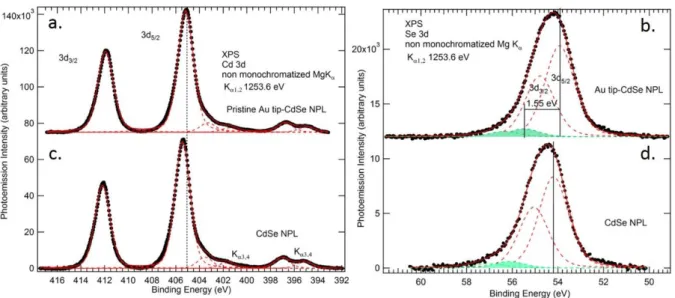
Figure 5. Background-subtracted Cd 3d (a) and Se 3d (b) spectra of the dithiol Au tip-CdSe NPL film sample with its silicon substrate biased to +5.9 V. The binding energy is rescaled to position at 84.00 eV the 4f7/2 peak of the sample bearing a (floating) macroscopic gold disk. (c) and (d) are respectively the same of the raw CdSe film. In all case, the excitation source is a non-monochromatized Mg K X-ray tube. The Mg K3,4 replicas are indicated.
For the Au tip-CdSe NPL film with dithiol ligands, see Figure 5(a), we find that the Cd 3d5/2 core-level is at 405.12 eV. This value is close to the one attributed to bulk CdSe: 38 405.3 eV. Due to their fabrication procedure and unavoidable exposure to air, the CdSe NPLs could have been oxidized. In fact we do not find evidence for the presence of CdO, whose Cd 3d5/2 binding energy is 404.2 eV (a rare case in which the binding energy of the oxide is smaller than that of the metallic state, namely 404.9 eV).
The Se 3d core-level gives further information on the chemistry of the gold-tipped NPLs. The spectrum of the Au tip-CdSe NPL film with dithiol ligands is presented in Figure 5 b after the due corrections for charging. The presence of SeO2, with a Se 3d5/2 binding energy39 of ≈58.8 eV is excluded, showing that the platelets resistance to oxidation is high (an exposure to air for 48 hours does not alter the picture). The small binding energy doublet (green component) could be attributed to surface Se atoms in contact with the ligands. Note that the binding energy of Se 3d5/2 in amorphous selenium is in the range 55.4-55.5 eV.40 The carbon and sulfur XPS signal relative to the thiol ligands of the Au tip-CdSe NPLs are discussed in the supplementary information, see figure S9 and S10.
A comparison with the CdSe NPL film with dithiol ligands deprived of gold tips is interesting. Due to charging effects, the same procedure as that used for the Au tip-CdSe NPL film is used (+5.9 V Si substrate bias, binding energy calibration with respect to the Au 4f7/2 peak of a macroscopic gold disk deposited on the surface). The Cd 3d spectrum is shown in figure 5 c. It has exactly the same shape as that of the gold-tipped NPL (figure 5 a). Therefore formation of gold nano-tips has no detectable effect on the chemistry of the CdSe nanoplatelets (e.g. oxidation). The only difference is a rigid shift of the binding energy. Indeed the Cd 3d5/2 binding energy position of the CdSe film is found at 405.43 eV
instead of 405.12 eV for the Au tip-CdSe NPL film. The same shift of ≈0.3 eV is seen for the Se 3d level (figure 5d). The Se 3d5/2 component of the CdSe film is at 54.20 eV, while it was at 53.92 eV for the Au tip-CdSe NPL film. Core-level binding energy shifts can be ascribed to changes in the position of the Fermi level in the gap of the semiconductor.41 This point will be discussed in detail in the next section.
Figure 6 (a) Background-subtracted Au 4f spectrum (filled circles) of the dithiol- Au tip-CdSe NPL sample with its silicon substrate biased to +5.90 V. The BE scale is then shifted by 6.12 eV. (b) Background-subtracted Au 4f spectrum (filled circles) of the Au tip-CdSe NPL sample on which a thick floating gold disk of diameter 0.5 mm is deposited. The Si substrate is polarized by +5.90 V. The BE scale is re-scaled to position the 4f7/2 peak at 84.00 eV. The excitation source is a non-monochromatized Mg K X-ray tube. The Mg K3,4 replicas are indicated.
In Figure 6, we compare the Au 4f core-level spectra of the Au tip-CdSe NPL film, where gold is under the form of nano-tips and that of the thick, macroscopic floating gold disk subsequently deposited on the Au tip-CdSe NPL layer. The spectra are shown after correction of the charging effect. Let us first consider the spectrum of the gold disk, whose 4f7/2 line is positioned at 84.00 eV. We observe that the 4f4/2 line of the Au nano-tips is found at 84.25 eV, instead of 84.00 eV for the macroscopic Au disk. The shift of +0.25 eV is significant, because the core-level binding energies of the other elements (Cd, Se, C, S) present in the Au tip-CdSe NPL film are identical (to a precision better than 40 meV, see SI, figure S8) before and after deposition of the macroscopic gold disk for the same Si substrate bias. Passing from bulk gold to nano-tips, we also observe a small increase in the FWHM from 1.28 eV to 1.45 eV (see Figure 6). However the observed shift is too small to correspond to any oxidation state of gold. Indeed, the literature indicates that the Au+ and Au3+ oxidation states are found at higher binding
energy than (metallic) Au0 by ≈1.2eV and 2.1 eV respectively.42 The oxidation of gold in O
3 gives a well-defined 4f7/2 peak43 at 85.22 eV. The binding energy increase from bulk gold to nano-tips could rather be attributable to a size effect, given the dimensions of the gold beads, in the 2 to 5 nm range.44,45 The
analysis of the Au 4f core-level spectrum indicates that the formed hybrid Au tip-CdSe NPL material is only composed of CdSe and Au0. Therefore, the formation of an Au
2Se compound, as proposed in our first scenario, is excluded.
Should there exist an electron transfer from the metal to CdSe (second scenario), inducing an (electron) carrier density increase, the Fermi level position in the gap would be affected and would move away from the valence band maximum. This in turn would change the work function (by definition, the energy difference between the vacuum level and the Fermi level) that would diminish, assuming that the electron affinity of the NPL is not modified by the addition of the gold-tips and that the gap energy remains the same. The latter hypothesis appears reasonable as XPS excludes the formation of Au2Se, that has a smaller gap than CdSe. Kelvin Probe Force microscopy (KPFM) measurements46 were carried out to measure the work function change between the “raw” CdSe films and Au tip-CdSe NPL films. KPFM measures the contact potential energy difference (q.VCPD) which is the work function of the tip (
tip
) minus that of the sample (
sample): qVCPD
tip
sample. To avoid a calibration of the tip workfunction, we rather choose to use a substrate with a known work function as a reference. To do so, we use a freshly cleaved MoS2 substrate, whose work function
2
MoS
is 4.8 eV.47 We carefully deposited (sub-monolayer) films of CdSe and Au tip-CdSe NPL on MoS2. Then we measured, in peak force mode, the topography (see Figure 7a) and by polarizing the tip, the surface potential, see Figure 7b. The use of a conductive tip in KPFM tends to reduce the spatial resolution (≈20 nm) compared to the topographic mode. As a result, the measured VCPD value is an average value over a whole(functionalized) nanoparticle. The sample work function is finally given by
)
(
)
(
2 2qV
CPDMoS
qV
CPDfilm
MoS film
. By measuring different areas of our sample we areFigure 7 a. Peak force image of Au tip-CdSe NPL film. b Kelvin probe microscopy image of the same area of the film. The inset is a potential profile corresponding to the grey line shown on the image. c Histogram of the sample work function with respect to the MoS2 work function, probed using KPFM, for a film of core CdSe NPL and for the Au tip-CdSe NPL film. d. Band diagram of CdSe NPL and Au tip-CdSe NPL with respect to MoS2. The scheme highlights a ≈400meV shift of the band of CdSe once functionalized by gold.
The KPFM work function of the CdSe NPL film is ≈4.2 eV, in excellent agreement with a “macroscopic” measurement (4.21 eV) using the low energy cutoff of the secondary electron energy distribution curve obtained during a photoemission experiment, see figure S11 of the supporting information. Figure 7 c shows that the work function of the Au tip-CdSe NPL film is 420 meV larger than that of the CdSe film. The fact that gold-tipping increases the work function indicates that the Fermi level (EFL) valence band maximum (EVBM) energy difference FL
VB
E =EFL-EVBM decreases by ≈0.42 eV between CdSe NPL and Au tip-CdSe NPL.
Concerning the samples studied by XPS (preceding section), we observed that the binding energy of the Cd 3d and Se 3d core-levels decreased by ≈0.3 eV passing from the CdSe film to the Au tip-CdSe
NPL film. Core-level shifts are only due to changes in the Fermi level position when the valence band maximum to core-level energy difference remains constant.48,49 This is indeed the case as the chemistry is not affected (one single chemical component is seen for the Au tip CdSe film). Therefore the decrease in core-level binding energy can be explained by a EVBFL value smaller by 0.3 eV for the gold-decorated platelets, in good qualitative agreement with the KPFM measurements. The Fermi level gets closer to the valence band maximum. The fact that the ligands are different (ethanedithiol for the XPS samples, oleate for the KPFM ones) is not relevant to the discussion, as each technique compares NPLs with and without gold but with identical ligand coverages.
The KPFM and XPS measurements point to a Fermi level getting closer to the valence band maximum. Note that the same motion of the Fermi level towards the valence band is observed in the UPS work of Ehamparam et al, 50 despite these authors draw conclusions contrasting with ours. Two schematical
explanations can be proposed: (i) an electron charge transfer from the semiconductor to the metal
occurs, or (ii) the doping of CdSe by gold atoms behaving as acceptors occurs.
Let us examine the first point. A decrease in EVBFL means a decrease in the electron carrier density, and even possibly hole-doping, while gold receives the electronic charge. A charge transfer to gold explains the decrease in intensity of the white line features previously observed in Au L3 edge x-ray absorption spectrum (2p3/2 to 5d5/2 dipole transition) passing from “bulk” gold to nano-beads attached to CdSe51 NPLs. Indeed the Au 5d holes (due to d-s-p hybridization, leading to a a 5d10–x 6(sp)1+x electron configuration) present in gold bulk get filled by electron charges transfered from the semiconductor. A “macroscopic” picture, based on the physics of the Schottky junction formation, is helpful to understand the phenomenon. The “raw” CdSe NPLs are believed to be intrinsic or lightly n-doped. A decrease in EVBFL could be explained by an upward band bending upon the formation of the metal/semiconductor interface assuming flat band conditions for the “raw” CdSe material. To affect the Cd 3d core-level (averaged over the whole NPL) the (electron) depletion width should be comparable to the longest dimension of the NPL (40 nm) given that the gold/CdSe interfaces are positioned at the edge of the platelets.
The second hypothesis (doping) must be also examined. During the gold-tipping process, the CdSe NPLs could be unwillingly doped by gold atoms (the insertion should be limited as an Au2Se phase is not detected). In bulk II-VI semiconductors, interstitial gold atoms behave as donors, while substitutional gold atoms behave as acceptors.52 With substitutional gold atoms, the CdSe NPLs could become p-doped, explaining the smaller EVBFL value. In fact, p-doping of CdSe nanoparticles by silver atoms (that behave like gold atoms) at high dopant concentration is proven in Ref. 53. However it must be
acknowledged that these p-doped CdSe NP by Ag do not exhibit evidence of hole-conduction. The reason for this behavior remains unclear.53
To decide whether gold-tipping influences (via Schottky barrier formation3 or impurity doping54) the conductivity of the NPLs or not, the question of hole mobility in CdSe needs to be clarified. In bulk CdSe, the hole drift mobility55 at 300 K is not negligible (75 cm2/Vs) compared to that of the electrons (in the range 130 to 720 cm2/Vs). However in CdSe nanocrystals, all the litterature31,32,56 agrees on the n-type nature of the conduction, meaning that the holes present an extremely low transport mobility. We can thus fully exclude the hypothesis of a hole charge transfer which would be responsible for the observed rise of conductance.
Actually the hole transfer toward the seconductor implies that the semiconductor is empty of any carrier with reasonable mobility in the Au tip-CdSe NPL system. It brings us to the conclusion that the semicondcutor actually plays no role in the charge transport (or it may marginaly impacts the conduction by increasing the overall dielectric constant of the medium). This conclusion is in good agreement with the results from the Klinke’s group obtained on the Pt-CdSe system,6 for which the transport may also be dominated by tunnel events between the metallic grains. Since the gold tips on a single NPL are spaced by a fairly large distance (≈10nm) for tunnel transport, the 3D nature of our film is critical to achieve a percolative path.
The present study also suggests other tracks to follow in order to demonstrate metal-semiconductor hybrid system with a higher degree of mixing of the electronic properties. A greater intrication of the two materials, without ligand spacing and with epitaxial connexion is probably necessary to achieve truely hybridized materials.
4. Conclusions
We propose various strategies to control the size and location of gold tips on CdSe NPLs. Traditional gold reduction carried out at room temperature (20°C) leads to the formation of small Au tips located at the edges, whose size can be controlled though photo-reduction. When the reaction is carried out at higher temperature (70°C), cation exchange tends to be favored, leading to the formation of the narrow band gap semiconductor Au2Se.
We also investigate the change in transport properties resulting from gold functionalization. In the presence of gold tips obtained by gold reduction, the conductance is increased by orders of magnitude. To understand the origin of this conduction enhancement, we examine the chemical bonding and the electronic structure using XPS and KPFM measurements. XPS indicates that the gold is present only
under the Au° form and we can exclude the formation of Au2Se and the correlated band gap reduction as a possible mechanism for the rise of conductance. Upon gold tipping, XPS and KPFM measurements point to a reduction of the energy difference between the Fermi level and the top of the valence band. We discuss why this phenomenon happens (electron charge transfer to gold and Schottky barrier formation, p-doping by substitutional gold atoms) and examine the consequences on the NPL film conductivity. As the electron carrier density is decreased and as we lack further knowledge about hole mobility in CdSe NPLs, we refrain from attributing the overall increase in conductance to an increased conductivity in the p-doped semiconductor. We rather favor the hypothesis that transport actually results from tunnel events between metallic tips and that the semiconductor plays a limited role here.
Acknowledgements
We thank Fausto Sirotti and Mathieu Silly from the Tempo beam-line of synchrotron SOLEIL, who gave us the opportunity to measure the CdSe work function. We also thank Etienne Rochette for help with the syntheses. This work was supported by French state funds managed by the ANR within the Investissements d'Avenir programme under reference ANR-11-IDEX-0004-02, and more specifically within the framework of the Cluster of Excellence MATISSE led by Sorbonne Universités. S.I. and A.O. thanks Agence Nationale de la Recherche (ANR) for funding through grant Nanodose and grant H2DH, respectively.
Supporting information
The supporting information includes details about the NPL material processing and the XPS methodology, in particular, the original procedure we used to eliminate differential charging in these low conductance material. This material is available free of charge via the Internet at
REFERENCES AND NOTES
1 Hines, M. ; Guyot Sionnest, P. Synthesis and Characterization of Strongly Luminescing ZnS-capped CdSe Nanocrystals. J. Phys. Chem., 1996, 100, 468–471
2 Bodnarchuk, M. I. ; Kravchyk, K. V. ; Krumeich, F. ; Wang, S. ; Kovalenko, M. V.. Colloidal Tin-Germanium Nanorods and Their Li-ion Storage Properties. ACS Nano, 2014, 8, 2360–2368.
3 Sheldon, M. T.; Trudeau, P.E.; Mokari, T.; Wang, L. W.; Alivisatos, A.P., Enhanced Semiconductor Nanocrystal Conductance via Solution Grown Contacts. Nano Lett. 2009, 9, 3676-3682.
4 Steiner, D.; Mokari, T.; Banin, U.; Millo, O. Electronic Structure of Metal-Semiconductor Nanojunctions in Gold CdSe Nanodumbbells. Phys. Rev. Lett. 2005, 95, 056805.
5 Mokari, T.; Sztrum, C. G.; Salant, A.; Rabani, E.; Banin, U. Formation of Asymmetric one-sided Metal-Tipped Semiconductor Nanocrystal Dots and Rods. Nat. Mat 2005, 4, 855-863
6 Meyns, M.; Willing, S.; Lehmann, H.; Klinke, C. Metal Domain Size Dependent Electrical Transport in Pt-CdSe Hybrid Nanoparticle Monolayers. ACS Nano 2015, 9, 6077-6087
7 Banin, U.; Ben-Shahar, Y.; Vinokurov, K. Hybrid Semiconductor-Metal Nanoparticles: From Architecture to Function, Chem. Mater. 2014, 26, 97-110.
8 Salant, A.; Amitat-Sadovsky, E.; Banin, U., Directed Self-Assembly of Gold-Tipped CdSe Nanorods, J.
Am. Chem. Soc 2006, 128, 10006-10007.
9 Mokari, T.; Rothenberg, E.; Popov, I.; Costi, R.; Banin, U. Selective Growth of Metal Tips onto Semiconductor Quantum Rods and Tetrapods. Science 2004, 304, 1787-1790.
10 Ithurria, S.; Dubertret, B. Quasi 2D Colloidal CdSe Platelets with Thicknesses Controlled at the Atomic Level. J. Am. Chem. Soc. 2008, 130, 16504-16505.
11 Ithurria, S.; Bousquet, G.; Dubertret, B. Continuous Transition from 3D to 1D Confinement Observed During the Formation of CdSe Nanoplatelets. J. Am. Chem. Soc. 2011, 133, 3070-3077.
12 Lhuillier E., Pedetti S., Ithurria S., Nadal B., Heuclin H., Dubertret B., Two-dimensional Colloidal Metal Chalcogenides Semiconductors: Synthesis, Spectroscopy, and Applications. Acc. Chem. Res. 2015, 48, 22-30.
13 Liu, Y.H.; Wayman, V. L.; Gibbons, P. C.; Loomis, R. A.; Buhro, W. E. Origin of High Photoluminescence Efficiencies in CdSe Quantum Belts. Nano Lett. 2010, 10, 352-357
14 Naskar, S.; Schlosser, A.; Miethe, J. F.; Steinbach, F.; Feldhoff, A.; Bigall, N. Site-selective noble metal growth on CdSe nanoplatelets. Chem Mat 2015, 27, 3159-3166.
15 Wu, K.; Li, Q.; Du, Y.; Chen, Z.; Lian T. Ultrafast Exciton Quenching by Energy and Electron Transfer in Colloidal CdSe Nanosheet–Pt Heterostructures, Chem. Sci. 2015, 6, 1049-1054
16 Zhukovskyi, M.; Tongying, P.; Yashan, H.; Wang, Y.; Kuno, M., Efficient Photocatalytic Hydrogen Generation from Ni Nanoparticle Decorated CdS Nanosheets. ACS Catal. 2015, 5 6615–6623
17 Lavieville, R.; Zhang, Y.; Casu, A.; Genovese, A.; Manna, L.; Di Fabrizio, E.; Krahne, R. Charge Transport in Nanoscale “All-Inorganic” Networks of Semiconductor Nanorods Linked by Metal Domains. ACS
Nano 2012, 6 2940–2947
18 Cargnello, M.; Johnston-Peck, A. C.; Diroll, B.T.; Wong, E.; Datta, B.; Damodhar, D.; Doan-Nguyen, V. V. T.; Herzing, A.A.; Kagan, C.R.; Murray C.B. Substitutional Doping in Nanocrystal Superlattices, Nature
2015, 524, 450-453.
19 Mahler, B. ; Nadal, B. ; Bouet, C. ; Patriarche, G. ; Dubertret B. Core/Shell Colloidal Semiconductor Nanoplatelets. J. Am. Chem. Soc. 2012, 134, 18591-18598.
20 Slyusarenko, K.; Abécassis, B.; Davidson, P.; Constantin, D. Morphology of Gold Nanoparticles Determined by Full-curve Fitting of the light Absorption Spectrum. Comparison with X-ray Scattering and Electron Microscopy Data, Nanoscale 2014, 6, 13527-13534.
21 Ueda, A.; Tayagaki, T.; Kanemitsu, Y. Energy Transfer from Semiconductor Nanocrystal Monolayers to Metal Surfaces Revealed by Time-resolved Photoluminescence Spectroscopy, Appl. Phys. Lett 2008, 92, 133118.
22 Gogorov, A.E.; Brynat, G.W.; Zhang, W.; Skeini, T.; Lee, J.; Kotov, N. A.; Slocik, J.M.; Naik, R.R. Exciton−Plasmon Interaction and Hybrid Excitons in Semiconductor −Metal Nanoparticle Assemblies,
Nano Lett. 2006, 6, 984-994.
23 Son, D.H.; Hughes, S.M.; Yin, Y.; Alivisatos, A.P. Cation Exchange Reactions in Ionic Nanocrystals.
Science 2004, 306, 1009-1012.
24 Beberwyck, B. J. ; Surendranath, Y. ; Alivisatos, A.P. Cation Exchange: A Versatile Tool for Nanomaterials Synthesis. J. Phys Chem C 2013, 117, 19759-19770.
25 Sahu, A. ; Kang, M.S. ; Kompch, A. ; Notthoff, C. ; Wills, A. W. ; Deng D., Winterer, M. ; Frisbie, C. D. ; Norris, D. J. Electronic Impurity Doping in CdSe Nanocrystals. Nano Lett 2012, 12, 2587-2594.
26 Mocatta, D., Cohen, G., Schattner, J., Millo, O., Rabani, E., Banin, U. Heavily Doped Semiconductor Nanocrystal Quantum Dots. Science 2011, 332, 77-81.
27 Bouet, C.; Laufer, D.; Mahler, B.; Nadal, B.; Heuclin, H.; Pedetti, S.; Patriarche, G.; Dubertret, B. Synthesis of Zinc and Lead Chalcogenide Core and Core/Shell Nanoplatelets Using Sequential Cation Exchange Reactions. Chem. Mater. 2014, 26, 3002−3008.
28 Chen, S.; Zhang, X.; Hou, X.; Zhou, Q.; Tan, W. Synthesis of CdS–Au
2S–Au Hybrid Dendritic Nanostructures. Materials Letters 2010, 64, 489-492
29 Lhuillier, E.; Robin, A.; Ithurria, S.; Aubin, H.; Dubertret, B. Electrolyte-gated Colloidal Nanoplatelets-Based Phototransistor and its Use for Bicolor Detection. Nano Lett. 2014, 14, 2715−2719.
30 Lhuillier, E.; Dayen, J-F; Thomas, D.O.; Robin, A.; Doudin, B.; Dubertret, B. Nanoplatelets Bridging a Nanotrench: a New Architecture for Photodetectors with Increased Sensitivity. Nano Lett 2015, 15, 1736-1742.
31 Lhuillier, E.; Ithurria, S.; Descamps-Mandine, A.; Douillard, T.; Castaing, R.; Xu, X.Z.; Taberna, P-L. ; Simon, P. ; Aubin, H. ; Dubertret, B. Investigating the n- and p-Type Electrolytic Charging of Colloidal Nanoplatelets. J Phys Chem C 2015, 119, 21795-21799.
32 Lhuillier, E. Pedetti, S.; Ithurria, S.; Heuclin, H.; Nadal, B.; Robin, A.; Patriarche, G.; Lequeux, N.; Dubertret, B. Electrolyte-gated Field Effect Transistor to Probe the Surface Defects and Morphology in Films of thick CdSe Colloidal Nanoplatelets. ACS Nano 2014, 8, 3813-3820.
33 Zhang, Z.; Yates, J. T. Band Bending in Semiconductors: Chemical and Physical Consequences at Surfaces and Interfaces. Chem. Rev. 2012, 112, 5520–5551
34 Lee, J.S.; Shevchenko, E. V.; Talapin, D. V. Au-PbS Core-Shell Nanocrystals: Plasmonic Absorption Enhancement and Electrical Doping via Intra-particle Charge Transfer. J. Am. Chem. Soc. 2008, 130, 9673–9675
35 Liu, Y. ; Gibbs, M. ; Puthussery, J. ; Gaik, S. ; Ihly, R. ; Hillhouse, H. W. ; Law, M. Dependence of Carrier Mobility on Nanocrystal Size and Ligand Length in PbSe Nanocrystal Solids. Nano Lett. 2010, 10, 1960-1969.
36 Kovalenko, M. V.; Scheele, M.; Talapin, D. V. Colloidal Nanocrystals with Molecular Metal Chalcogenide Surface Ligands. Science 2009, 324, 1417-1420.
37 Lhuillier, E.; Keuleyan, S.; Zolotavin, P.; Guyot-Sionnest, P. Mid-infrared HgTe/As
2S3 Field Effect Transistors and Photodetectors. Adv. Mat. 2013, 25, 137-141.
38 Gaarenstroom, S. W.; Winograd, N. Initial and Final State Effects in the ESCA Spectra of Cadmium and Silver Oxides. J. Chem. Phys. 1977, 67, 3500.
39 Katari, J. E. B.; Colvin, V. L.; Alivisatos, A. P. X-Ray Photoelectron Spectroscopy of CdSe Nanocrystals with Applications to Studies of the Nanocrystal Surface. J. Phys. Chem. 1994, 98, 4109–4117
40 Canava, B.; Vigneron, J.; Etcheberry, A.; Guillemoles, J. .; Lincot, D. High Resolution XPS Studies of Se Chemistry of a Cu(In, Ga)Se2 Surface. Appl. Surf. Sci. 2002, 202, 8–14.
41 W.F. Egelhoff Jr. Core-level Binding-energy Shifts at Surfaces and in Solids, Surf. Sci. Rep. 1987, 5, 253-415.
42 Casaletto, M. P. ; Longo, A. ; Martorana, A. ; Prestianni, A. ; Venezia, A.M. XPS study of Supported Gold Catalysts: The Role of Au° and Au+1 Species as Active Sites. Surf. Interface Anal. 2006, 38, 215 – 218
43 Klyushin, A. Y.; Rocha, T. C. R.; Hävecker, M.; Knop-Gericke, A.; Schlögl, R. A near Ambient Pressure XPS Study of Au Oxidation. Phys. Chem. Chem. Phys. 2014, 16, 7881–7886.
44 Hövel, H.; Grimm, B.; Pollmann, M.; Reihl, B. Cluster-Substrate Interaction on a Femtosecond Time Scale Revealed by a High-Resolution Photoemission Study of the Fermi-Level Onset. Phys. Rev. Lett.
1998, 81, 4608–4611.
45 Howard, A.; Clark, D. N. .; Mitchell, C. E. .; Egdell, R.; Dhanak, V. . Initial and Final State Effects in Photoemission from Au Nanoclusters on TiO2. Surf. Sci. 2002, 518, 210–224
46 Melitz, A.; Shen, J.; Kummel, A.C.; Lee, S. Kelvin Probe Force Microscopy and its Application, Surf. Sci.
Rep. 2011, 66, 1-27.
47 Kennou, S.; Ladas, S.; Papageorgopoulos, C. The Interaction of Cs and O
2 on the Basal Plane of MoS2.
Surf. Sci. 1985, 164, 290–304.
48 G. Hollinger, Photoelectron spectroscopies: probes of Chemical bonding and electronic properties at semiconductor interfaces, in semiconductor interfaces: formation and properties, edited by G. Le Lay, J. Derrien and N. Boccara. Springer proceedings in Physics 1987, 22, 216-218.
49 Himpsel, F.; Hollinger, G.; Pollak, R. Determination of the Fermi-Level Pinning Position at Si(111) Surfaces. Phys. Rev. B 1983, 28, 7014–7018.
50 Ehamparam, R.; Pavlopoulos, N.G.; Liao, M.W.; Hill, L.J.; Armstrong, N.R.; Pyun, J.; Saavedra, S.S. Band Edge Energetics of Heterostructured Nanorods: Photoemission Spectroscopy and Waveguide Spectroelectrochemistry of Au-Tipped CdSe Nanorod Monolayers, ACS Nano 2015, 9, 8786-8800. 51 Teng, X.; Jia, X. Xiaowei Teng and Xiaoxiong Jia (2012). Cadmium Selenide-Gold (CdSe-Au) Hybrid Nanowires: Synthesis and Study of Charge Transfer, Nanowires - Recent Advances, Prof. Xihong Peng (Ed.), DOI: 10.5772/52828. Available from: http://www.intechopen.com/books/nanowires-recent-advances/cadmium-selenide-gold-cdse-au-hybrid-nanowires-synthesis-and-study-of-charge-transfer 52 Nedeoglo, N.D.;Sirkeli, V. P.; Nedeoglo, D.D.; Laiho, R.; Lähderanta, E. Electron Configuration and Charge State of Electrically Active Cu, Ag and Au Ions in ZnSe, J. Phys. Cond. Matt. 2006, 18, 8113-8127. 53 Sahu, A.; Kang, M.S.; Kompch, A.; Notthoff, C.; Wills, A. W.; Deng, D.; Winterer, M.; Frisbie, C.D.; Norris, D.J. Electronic impurity doping in CdSe nanocrystals, Nano Lett. 2012, 5, 2587-2594.
54 Norris, D. J.; Efros, A.L.; Erwin, S.C. Doped Nnaocrystals, Science 2008, 319, 1776-1779.
55 II-VI and I-VII Compounds; Semimagnetic Compounds’ of Volume 41 ‘Semiconductors’ of Landolt-Börnstein - Group III Condensed Matter. Cadmium selenide (CdSe) hole mobility, carrier and ion diffusion
56 Yu, D.; Wang, C.; Guyot-Sionnest, P. n-Type conducting CdSe nanocrystal solids, Science 2003, 300, 1277-1280.