Development of Heterogeneous CAD Assembly Tools
for Collaborative Design
By Kristie Yu
Bachelor of Engineering in Mechanical Engineering
Cooper Union for the Advancement of Science and Art, New York, NY 10003 Master of Science in Mechanical Engineering
Massachusetts Institute of Technology, Cambridge, MA 02139 Submitted to the Department of Mechanical Engineering In Partial Fulfillment of the Requirements for the Degree of
Mechanical Engineer at the
Massachusetts Institute of Technology May 2002
i
C 2002 Massachusetts Institute of Technology, All Rights Reserved
MASSAC iUSS IMTTu'
OF TECHNOLOGY
OCT
2 5 2002
LIBRARIES
Signature of A uthor...
Department of Mechanical Engineering May 10,;0,2
Certified by...
David Wallace Esther and Harold E. Edgerton Associate Professor of Mechanical Engineering Thesis Supervisor
A ccepted by...
0...--xm a. Sonin Chairman, Department Committee on Graduate Studies
Development of Heterogeneous CAD Assembly Tools
for Collaborative Design
By Kristie Yu
Submitted to the Department of Mechanical Engineering on May 10, 2002 in Partial Fulfillment of the Requirements for the Degree of Mechanical Engineer in
Mechanical Engineering
ABSTRACT
The next generation of CAD plug-ins for DOME3 was developed for use in the
heterogeneous CAD assembly design process originated from the MIT CADlab. This process utilizes DOME in exchanging assembly level parameters to remote native CAD models and coordinating the exchange of up-to-date neutral files. In addition, a VRML and Java based graphic user interface for assisting heterogeneous CAD assembly
designers in designing assemblies through DOME was also developed. Among its
features are the abilities to traverse native and imported components through a Swing assembly tree and access their design parameter information, set constraints on design parameters, modify design parameter values, and arrange design configurations on a per component basis. A case study on the design of half a rear suspension system, composed of an imported STEP flange assembly, was performed utilizing the tools developed for this thesis. Results indicate that the developed DOME CAD plug-ins and DOME VRML module have great potentials for current and future applications.
Abstract 1
Table of Contents
Acknowledgements...
4List of Figures...
5
L ist of T ab les...
91 Introduction
1.I. Background...101.11. Literature Review and Commercial Solutions... 15
1.111. Thesis Objective...23
2 New Assembly Process 2.1 Introduction... 28
2.11. Linking CAD Plug-Ins to DOME... 34
2.111. Basic Plug-In Functionalities and Requirements...34
2.III.A. Exporting Components... 37
2.III.B. Importing Components...43
2.IV. Unigraphics Plug-In...45
2.IV.A. Unigraphics Plug-In Interface Specification...49
2.IV.B. Import Issues Specific to Unigraphics... 54
2.V. I-deas Plug-In... 57
2.V.A. I-deas Plug-In Interface Specification...58
2.V.B. Import Issues Specific to I-deas... 63
2.VI. Summary and Conclusions... 65
3 DOME VRML Module
3.1. Introduction ... 69
3.11. Overview of New Features Offered... 69
3.111. VRML Module Functionalities and Requirements...70
3.III.A. The Design Interface...73
3.III.B. The Component Manager...82
3.III.C. The Configuration Manager...86
3.IV. Required VRML Components...91
3.V. Summary and Conclusions...97
4 Case Study
4.1. Introduction ... 994.11. Supplier Preparation Process: Setting Up the Flange Assembly...101
4.111. Assembly Designer Preparation Process: Setting Up the Half Rear Suspension Assembly...107
4.IV. Rear Suspension Assembly Designer: Working With the DOME VRML Module...112
4.V. Summary and Conclusions...138
5 Conclusions and Future Work 5.1. C onclusions... 140
5.11. Future W ork... 142
6 R eferen ces...143
Table of Contents 3
Acknowledgements
I'd like to thank my family for their continued support and guidance. Without them, I wouldn't be the person I am today. Thanks for all your wonderful words of encouragements and for always believing in me. Thanks to Prof. David Wallace for giving me the wonderful opportunity to work at the MIT CADlab and be a part of something special. Thanks to Ford and Mr. Peter Sferro for sponsoring my research and proving me with the opportunity to work on an industry problem. Thanks to Elaine for being not only a mentor but also a great friend. And a big thanks to the following members of the CADlab family for being such an awesome, supportive, fun, and smart bunch: Aubrey, Charles, Ed, Ines, Jaehyun, Keiko, Maureen, Prabhat, Qing, Sane, and Twiggy. Special thanks to Twiggy for always bringing the best snacks to the lab so I can munch on them while I work and Sane for hanging out with me at the movies. I wish you all the best of health and prosperity for years to come.
Acknowledgements 4
List of Figures
Figure 2.1 Designers Working In Their Respective CAD Systems...29
Figure 2.2 Assembled Bolted Joint Assembly...29
Figure 2.3 Working With DOME And Establishing Relevant Relations...30
Figure 2.4 Increasing the Length and Thickness of the Plate... 31
Figure 2.5 Propagating Changes in Design Parameters From the Assembly Designer to the Suppliers...32
Figure 2.6 Updated Bolted Joint Assembly... 33
Figure 2.7 CAD Plug-In Initialization Information Flow Diagram...36
Figure 2.8 Sample "density.txt" file... 41
Figure 2.9 Sample "import.txt" file... 44
Figure 2.10 Unigraphics CAD System... 46
Figure 2.11 Unigraphics DOME Version 1 Interface...47
Figure 2.12 DOME VRML Module... 48
Figure 2.13 I-deas CAD System... 57
Figure 2.14 CAD Plug-In Export Interaction Information Flow Diagram... 66
Figure 2.15 CAD Plug-In Import Interaction Information Flow Diagram... 67
Figure 3.1 DOME VRML Interface... 72
Figure 3.2 The VRML Module Design Interface... 73
Figure 3.3 Sample Part Component Data File... 75
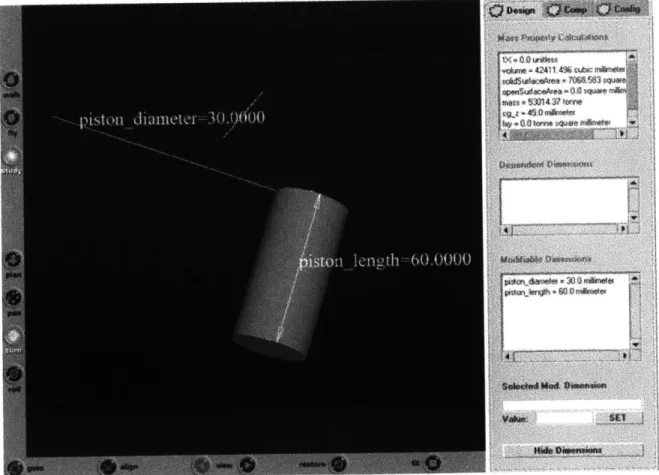
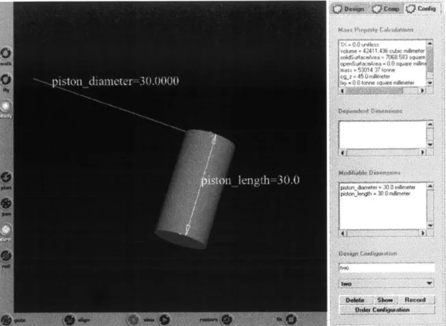
Figure 3.4 Selecting Modifiable Dimension Objects through the VRML Module... 76
Figure 3.5 Entering Invalid Values for the Selected Modifiable Dimension... 77
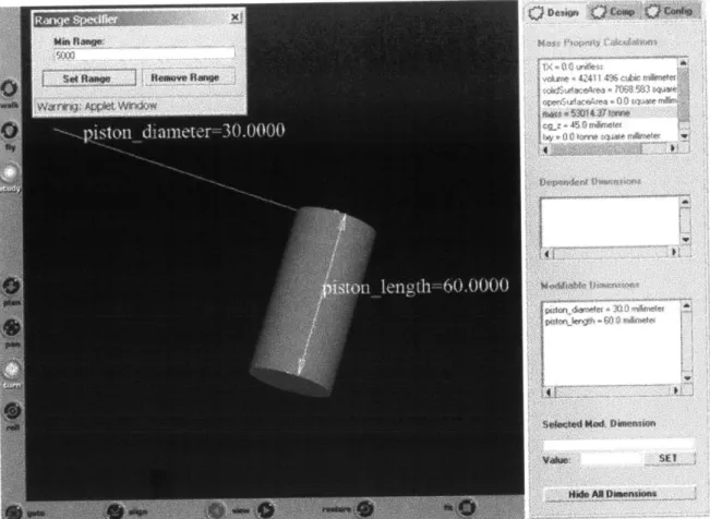
Figure 3.6 Setting Limits on a Design Parameter...78
Figure 3.7 Entering Limit on a Design Parameter...79
Figure 3.8 Hiding Dimension Objects... 80
Figure 3.9 Exceeding Design Parameters... 81
Figure 3.10 The VRML Module Component Manager...83
Figure 3.11 Selecting Component Using the Pull Down Menu...84
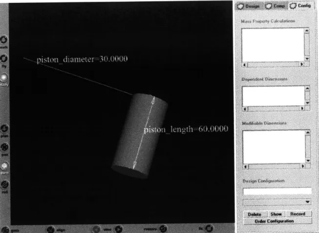
Figure 3.12 The VRML Module Configuration Manager... 87
Figure 3.13 Recording a Design Configuration...88
Figure 3.14 Recalling a Design Configuration... 89
Figure 3.15 Deleting a Saved Configuration... 90
Figure 3.16 Ordering Saved Configurations...91
Figure 3.17 VRML Module and CAD Plug-In Information Flow Diagram...97
Figure 4.1 Flange Assembly... 101
Figure 4.2 Seal Assembly... 101
Figure 4.3 O uter Seal... 102
Figure 4.4 Inner Seal...102
Figure 4.5 Flange Fin...102
Figure 4.6 Flange Assembly "density.txt" File...103
Figure 4.7 Unigraphics CAD Plug-In "flange assembly.in" Input File... 104
Figure 4.8 Flange Assembly "flangeassembly.txt" File... 105
Figure 4.9 Half Rear Suspension Assembly... 106
Figure 4.10 Rear Suspension Designer's "import.txt" File... 107
Figure 4.11 Assembled Half Rear Suspension... 109
6 List of Figures
Figure 4.12 I-deas CAD Plug-In "RearSuspension.in" Input File...110
Figure 4.13 DOME VRML Module's "Rear Suspension.dat" Input File...111
Figure 4.14 DOME VRML Interface for Half Rear Suspension Assembly... 113
Figure 4.15 Setting Limits on Design Parameters... 114
Figure 4.16 Entering Value for the Design Parameter Bounding Limit... 114
Figure 4.17 Viewing The Bounding Limit Just Set... 115
Figure 4.18 Component Manager Pull Down Menu...116
Figure 4.19 Expanded Component Manager Swing Assembly Tree...116
Figure 4.20 Expanded Component Manager Swing Assembly Tree...117
Figure 4.21 C arrier Fin... 118
Figure 4.22 Selecting a Dependent Dimension Design Parameter... 119
Figure 4.23 Selecting a Modifiable Dimension Design Parameter...119
Figure 4.24 Changing a Modifiable Dimension Design Parameter...120
Figure 4.25 Updated VRML Scene and Design Interface for Carrier Fin...121
Figure 4.26 Rear Auxiliary Suspension... 122
Figure 4.27 Recording a Design Configuration...122
Figure 4.28 Recalling a Design Configuration... 123
Figure 4.29 Modifying a Dimension Design Parameter... 124
Figure 4.30 Updated VRML Scene and Design Interface for Rear A uxiliary Suspension... 124
Figure 4.31 Recording a Design Configuration...125
Figure 4.32 Arranging Stored Design Configurations...126
Figure 4.33 Resulting Configuration Manager... 126
List of Figures 77
Figure 4.34 Deleting a Saved Design Configuration... 127
Figure 4.35 Remaining Configuration Saved For the Rear Auxiliary Suspension.... 128
Figure 4.36 Flange Assembly... 129
Figure 4.37 Selecting Inner Seal within the Flange Assembly... 130
Figure 4.38 Inner Seal... 130
Figure 4.39 O uter Seal... 131
Figure 4.40 Seal Assembly... 131
Figure 4.41 Flange Fin... 132
Figure 4.42 Modifying the Design Parameter of Imported Component Flange Fin.. 133
Figure 4.43 Updated Flange Fin... 134
Figure 4.44 Updated Flange Assembly...134
Figure 4.45 Updated Half Rear Suspension Assembly...135
Figure 4.46 Exceeding Design Parameter Bounds for Components...136
Figure 4.47 Flange Fin...137
List of Figures 8
List of Tables
Table 2.1 Sample DOME Unigraphics Plug-In Interface Specification Files...52 Table 2.2 Sample DOME I-deas Plug-In Interface Specification Files...61
List of Tables 99
Chapter 1: Introduction
I. Background
In the 1970's, the U.S. automotive industry sought to protect its market share from imports by improving its own productivity and competitiveness through outsourcing components and concurrent engineering. As a result, lead times were reduced and the productivity gap significantly narrowed between the U.S. automotive industry and its competitors [Brunnemeier and Martin 1999].
The automotive supply chain evolved from vertically integrated organization to consist of original equipment manufacturers (OEM), first tier suppliers, sub-tier suppliers, and infrastructure suppliers. However, as the nature of the relationship between the involved parties became more complex, such as when a particular company take on business with different OEMs within the supply chain, the ability to share computer aided design (CAD) data during product design and manufacturing becomes increasingly more important. Many companies use CAD systems for communicating product design intent. Unfortunately, due to a lack of common standard for CAD model formats, companies that manufacture various components of an end-product are not able to seamlessly transfer parametrically editable data up and down the organizational structure [Kelly 2001].
In a supply or design chain, such as the automotive, many different software and hardware systems are used during the design process. Because each system has its own
10 Chapter 1: Introduction
proprietary data representation, product data are created and stored in multiple, incompatible formats, which makes exchanging these data difficult and often results in data files that may contain error, be incomplete, or be formatted in a way that makes them unusable for downstream applications [Brunnemeier and Martin 1999]. This contributes to the problem of CAD interoperability.
Studies have shown CAD interoperability costs the automotive industry roughly 1 billion dollars annually [Brunnemeier and Martin 1999] and the discrete manufacturing industry roughly 20 billion [PTC 2001]. For the automotive industry, there are three different types of costs related to interoperability problems. They are avoidance, mitigating, and delay costs.
Avoidance costs are incurred when automakers attempt to prevent interoperability problems before they can occur. They include: the cost of purchasing, maintaining, and training for CAD/CAM systems for the purpose of native format translation; the cost of purchasing, maintaining, and training of point-to-point translation software; the cost of purchasing, maintaining, and training for neutral format translation software; outsourcing costs incurred when outside companies are hired to provide data exchange services; investments in in-house programs aimed at addressing interoperability issues, such as implementing STEP or training engineers in proper product model creation; and, the cost of participating in industry consortia activities aimed at improving interoperability through the industry [Brunnemeier and Martin 1999].
Mitigating costs are incurred when automakers attempt to address interoperability problems after they have occurred. They include: the cost of reworking scrapped models, designs, prototypes, parts, dies, etc., that were incorrect due to interoperability problems;
Chapter 1: Introduction 11
and, the cost of manually reentering data when other methods of data exchange are unavailable or unsatisfactory [Brunnemeier and Martin 1999].
Delay costs are incurred when automakers fail to meet production schedule due to interoperability problems. They include: profits lost due to decline in market share caused by delays; profits lost due to delay of revenues; and, losses of consumer welfare due to delay of the availability of products with greater net value [Brunnemeier and Martin 1999].
The main cause of interoperability problems stem from a lack of standardized CAD format within a given industry. The lack of a standardized CAD format can be attributed to one important necessity, the modeling kernel that is the brains of the CAD application [Kelly 2001]. Within an existing industry, CAD applications can be created from a proprietary kernel or from a commercially available kernel [Kelly 2001]. For example, Structural Dynamics Research Corporation's (SDRC) I-deas, Parametric Technology Corporation's (PTC) Pro/Engineer, and Dassault Systemes' Catia all use their own proprietary kernels. While UGS's Unigraphics uses UGS's Parasolid kernel and SolidWorks uses Spatial Technology Corporation's ACIS kernel. Both Parasolid and ACIS are commercially available kernels.
In an attempt to combat the interoperability problem, OEMs and suppliers have tried to standardize their CAD packages. Point-to-point and neutral format translators were also developed. Standardizing CAD systems across OEM and suppliers does not necessarily eliminate interoperability problems since they would surface when the supplier attempts to exchange CAD data with another OEM supplier operating under a different CAD system. Point-to-point translators work fine for some cases, but requires
Chapter 1: Introduction 1212
constant updates to keep up with the latest version of CAD packages. Also, specific translators would be required based on which CAD system is doing the sending and reading.
Neutral format translators such as the Initial Graphics Exchange Specification (IGES) and the Drawing eXchange Format (DXF) were limited in their success in their early days, but have improved significantly with newer versioning standards. Recently adopted by the International Standards Organization (ISO) and developed by more than 38 countries, the Standard for the Exchange of Product Data Model (STEP) translator was developed to extend data exchange capabilities to all aspects of a product's life cycle, from material specification to after-sale maintenance [Brunnemeier and Martin
1999]. Various tests conducted by industry participants have shown that the STEP translator outperforms both IGES and DXF translators.
It should be noted here that the IGES, DXF, and STEP neutral file standards are used in the automotive industry. In other industries, such as the Architecture, Engineering, and Construction (AEC) industry, different neutral format standards are used. Cadalyst has a very interesting article on six AEC software vendors' views on the CAD interoperability issue within their industry [Cadalyst 2001].
The key advantage of using neutral format translators is that it protects proprietary knowledge in the way the detailed models are built. However the key disadvantage of using neutral, tessellated files is that the geometry is not parametrically editable. That, coupled with versioning issues between the OEM and supplier, may adversely add to design iteration cycle times. Hence, if the neutral format solution is to be used, there needs to exist an approach that will compensate for its limitations by eliminating
Chapter 1: Introduction 13
versioning issues and speeding up design iteration cycles for a heterogeneous CAD assembly composed of native and neutral file components.
As section II will indicate, considerable research has been devoted to the area of CAD interoperability and numerous solutions proposed. It is not the intent of this thesis to propose a solution that will completely eliminate all problems associated with CAD interoperability. It is rather, the intent of this thesis to propose and present several tools developed at the MIT CADlab for use in assisting assembly engineers in the design of heterogeneous CAD assemblies that may help in reducing cost associated with CAD interoperability.
One of the major problems associated with CAD interoperability through neutral files is its impediment on the rapid design iteration cycles desired of an assembly composed of parts from several different CAD systems. There are traditionally two ways in which such an assembly is constructed: brining a directly converted version of the model from the sender's system to the receiver's system, or importing a neutral file version of the model into the receiver's system. Regardless of which form is made available to the assembly designer, if there does not exist an efficient method in which she can perform design iterations, it will be an expensive process.
Many of the solutions presented in section II deal with providing solutions targeting towards solving the CAD interoperability issue, but they are not integrated efficiently, if at all, into the assembly designer's design iteration cycle process. Other integrated solutions, such as design workspaces, work more efficiently but at the expense of divulging all proprietary information associated with a native CAD model. Oftentimes, when working with assembly designers outside of their company, suppliers
Chapter 1: Introduction 14
would rather that non-sensitive, non-proprietary information embedded within their native CAD files, such as design history, are not transmitted as a result of the process.
So, several needs were identified for both the assembly designer and parts suppliers in working collaboratively on a heterogeneous CAD assembly design: minimize issues associated with CAD interoperability, quick design iteration cycle times, correct versioning models, and protection of proprietary data. A unique solution arrived at the MIT CADlab seeks to satisfy all those needs.
In minimizing issues associated with CAD interoperability, neutral files exported by CAD systems such as IGES and STEP are used as the means for transferring models from one CAD system to another. This choice also satisfies the need to protect proprietary data. To satisfy the needs of quick design iteration cycle times and correct versioning models, DOME's inherent features will be used. DOME, which stands for distributed object based modeling environment, is a web based design application tool that allows engineers to engage in concurrent engineering [Abrahamson, et Al. 2000] [Senin, et Al. 1997]. Tools developed by this author that enable this process are the main focus of this thesis.
II.
Literature Review and Commercial SolutionsBoth academia and industry analysts have conducted extensive research on the problem of CAD interoperability. Sources of the problems were identified and the pros and cons associated with each available solution were investigated. From the research gathered for this thesis, it is apparent that most of the solutions proposed for solving CAD
Chapter 1: Introduction 1515
interoperability problems came from members of the industry and commercial companies, not the academia. This is understandable since CAD interoperability problems are tied to CAD user practices and the exchange of files between different CAD
systems.
The solutions would require proper training and software solutions. Neither of which are particularly suitable for academia studies nor do they generate a tremendous amount of interest in the academia world. Software solutions in the form of new standards for exchanging CAD information are beyond what the academia can dictate. Plus, the academia is not in the position to enforce industry standards. Only members of the industry, who propose and adopt the new standards, are. Of the proposed standards for exchanging three-dimensional (3D) CAD information across different systems, the neutral file standards of IGES and STEP are the most popular.
Other types of software solutions are also not ideal for academic studies in that numerous commercial companies already offer their own unique solutions. Some major CAD software companies have started offering their proprietary kernel to outside participants in an attempt to address the CAD interoperability problem by advocating the standardization of CAD kernels into their own proprietary kernel. PTC is offering its Granite One platform, the proprietary kernel of Pro/Engineer, to its customers and various software partners.
More commonplace solutions are ones that address the generation of bad models resulting from either inadequate translation services or bad modeling practices. ITI Transcendata offers various services catered towards solving bad data and interoperability problems [Transcendata 2002]. CADIQ, a software tool produced by ITI
Chapter 1: Introduction 1616
TranscenData, analyzes native CAD models to identify topological and geometric defects before models are released, thus saving the time and expense associated with model rework [CADIQ 2002]. BadCAD is both a provider and reseller of various data quality and CAD interoperability services [BadCAD 2002]. It also offers consulting services that make use of their software suite. One of its software packages allows user to manipulate and heal bad data it discovers to improve chances of successful translations. Another provides translations services from one proprietary system to another.
There is plenty of CAD file transferring services available today as well. CADCAM-E provides various native and neutral CAD file translation services [CADCAM-E 2002]. Spatial provides several services, among which is 3D InterOp, which facilitates in the transfer of 3D CAD data between different native formats and platforms [Spatial 2002]. Spatial also provides other services in the modeling and visualization sector.
In 1999, Spatial offered 3Dmodelserver.com, a web-based software application for repairing and improving 3D CAD models, for a trial period. This service does not appear to be currently operating and is not listed on Spatial's web site as one of its available services. So, one can assume that it may not be offered in the future even though the idea behind it was novel. 3Dmodelserver.com allowed subscribers to import models of IGES, STEP, and ACIS SAT formats onto its server. The application installed on the server will then identify areas for improvement on those models, attempt to fix them, and save the healed model in IGES, STEP, and ACIS SAT formats for incorporation into the subscribers' native CAD packages. All required software resided
Chapter 1: Introduction 17
on the web, so users always had access to the latest version of software and never needed to worry about installing the required software on their system.
Cadverter.com is an Internet based CAD/CAM data translation service [Cadverter 2002]. It supports the translation of numerous products, supports conversion of CAD geometry, assembly structure, and attribute data. It levies a fixed price pay as you use fee system. Translation Technologies Inc. (TTI) also offers native CAD translation services. Its flagship product, Acc-u-Trans, requires the user to first send his native file to the TTI secure server. Then the native file will be translated and converted into the designated native file format, complete with fully modifiable feature based parameters and functionality history tree [Translation Technologies Inc. 2002]. CADKEY Corporation's flagship product, CADKEY, allows users to import neutral and native two-dimensional (2D) CAD drawings and 3D CAD models into its proprietary system for direct manipulation of translated data [CADKEY 2002].
CoCreate's flagship product OneSpace offers a design workspace that allows users to conduct concurrent engineering [CoCreate 2002]. OneSpace helps companies collaborate by providing an infrastructure for teams to review, comment on, and change designs online in real time, regardless of the CAD system used to create the designs [MacKrell 2001]. OneSpace allows users to view data from multiple CAD systems, allows authorized users to modify those CAD models during the collaborative session, and allows users to construct assemblies from multiple CAD systems [MacKrell 2001]. With regards to working with 3D models, OneSpace supports the import of native geometry with parametric support. Modifications made to imported models within OneSpace can propagate back towards the original native model.
Chapter 1: Introduction 1818
When it comes to areas of concurrent engineering, collaborative design and distributed design, one can find many works and solutions proposed by members of the academia [De Martino and Giannini 1997], [Gao and Bennett 1997], [Ray, et Al. 1999]. Caldwell and associates came up with a decision-support tool that operates in design-guidance, knowledge-viewing, and knowledge-capture modes called WebCADET, which stands for web-based Computer-Aided Design Evaluation Tool [Caldwell, et Al. 2000]. LaViola and associates worked in the area of real-time distributed multi-media environment for collaborative engineering. They presented a new approach to the design of a shared virtual environment that addressed issues of scalability, networking, and synchronization, and discussed its applicability to collaborative design [LaViola, et Al. 1997].
Lombeyda and Regli developed a modeling system named CUP, which stands for Conceptual Understanding and Prototyping, that enables users to create a knowledge-level description of design in a collaborative, multi-user environment without having to perform detailed CAD and solid modeling [Lombeyda and Regli 1999]. Thus far, it allowed a team of design engineers, collaborating over the Internet, to develop a high-level structure-behavior function (S-B-F) description of an assembly in a VRML (Virtual Reality Modeling Language) based virtual environment [Lombeyda and Regli 1999]. Ikonomov proposed a virtual manufacturing and assembly system tool for concurrent engineering that made use of STEP files and the information embedded within them to evaluate designs for manufacturability and assemblability [Ikonomov 2000].
Central to concurrent engineering is the sharing of 3D model and data. Rossignac investigated the shortcomings of the current technology regarding the utilization of 3D
Chapter 1: Introduction 1919
data throughout all phases of a product life cycle, identified the fundamental research issues, and reviewed recent advances in 3D data compression, in the automatic generation of levels-of-detail for interactive rendering, and in the innovative exploitation of 3D input devices for an intuitive and effective navigation [Rossignac 1997].
A trend that could be seen in the concurrent engineering and product design fields is the migration of design tools towards the Internet and virtual environments. Fernando and associates worked on developing a constraint-based virtual environment for supporting assembly and maintainability tasks [Fernando, et Al. 2000]. Ranky and associated conducted research into developing a web-enabled virtual disassembly manager (webVDM) for electronic products [Ranky, et Al. 2000] [Ranky, et Al. 2001]. University of California at Berkeley has created WebCAD, a web-based, destructive solid geometry tool that allows users to create components for integration with CyberCut [WebCAD 1999]. WebCAD will automatically generate a process plan and verify whether the designed component can be manufactured on a 3-axis milling machine.
Danesi and associates researched into creating a web-based distributed CAD system where the client has access to data stored on the server [Danesi, et Al. 2001]. Different options for underlying architecture were examined and a prototype tested. Beazley and Chapman investigated how VRML is used in engineering applications, and what potential possibilities it holds for future collaborative engineering design projects [Beazley and Chapman 1996]. Wang and company used distributed computation (in the forms of Java and CORBA) and computer graphics (in the form of VRML) to implement a collaborative and interactive client-server design framework for use in the design of rooms over the Internet [Wang, et Al. 2000].
Chapter 1: Introduction 20
Luchi and associates utilized VRML, Java, and the Internet to create Web/Assembly [Luchi, et Al. 2001]. Web/Assembly enables virtual assembly on the web without requiring the presence of a CAD system. However, CAD systems are required for exporting components in the VRML format for incorporation into the Web/Assembly. Another feature of the Web/Assembly is the availability of a parts VRML catalog. Nousch and Jung used VRML, Java, and JavaScript to create BEAVER, a web based application that allows users to interactively design furniture on the web and generate shopping lists for components and customized assembly instructions [Nousch and Jung 1999]. Jung has also conducted research into bringing the Virtual Constructor (VC) to the Internet. VC is a knowledge-based distributed system that enables an interactive assembly of 3D visualized mechanical parts to complex aggregates [Jung 2001]. By step-keepingly matching the geometry scene against a structured model of the target aggregate, an assembly can be dynamically conceptualized [Jung 2001].
Ramos and associates developed an Internet accessible VRML and Java based airship simulator based on airship dynamic models, where the simulator is meant to be used as a tool for the development of control and navigation methods for autonomous and semi-autonomous robotic airships and as test bed for airship pilot training [Ramos, et Al. 1999]. Park and company conducted research into the development of a three-dimensional web monitoring system using a VRML browser for visualization [Park, et Al.]. Direct application areas include the monitoring of a product as it goes through an assembly line. In the area of manufacturing, a VRML web based system for accessing manufacturing data called VIM (Visual Interface to Manufacturing) was developed [VIM 2001].
Chapter 1: Introduction 21
Immersive Design's flagship product, Interactive Product Animator (IPA), provides animation and web publishing solutions that allow communication of 3D product information for interactive assembly, maintenance and repair documentation, product catalogs, and product presentations [Immersive Design 2002]. IPA supports native CAD formats and outputs in several formats, some of which are proprietary to Immersive Design, others are standard, such as Windows based AVIs and VRML files. IPA also supports hierarchical assembly tree displays, basic geometry creation, insertion of assemblies and parts, and automatic update of supported CAD components.
Kiss investigated into the development of a web based VRML modeling system for creating mesh models [Kiss]. His article provides an excellent introduction on how to use Java, VRML, and EAI in creating an interactive VRML session. Lots of companies also provide VRML based services. For example, ParallelGraphics specializes in providing web based visualization services, most of which makes use of VRML and its VRML browser, Corona [ParallelGraphics 2002]. SiteSculptor is Sculptware LLC's, a spinoff of CADKEY Inc., VRML based 3D modeling tool that constructs sold models from NURBs (Non-Uniform Rational B-Splines) [SiteSculptor 2001].
Many tools for marking up CAD geometries have also been developed. They are useful for conveying information between different viewers of a common design. Solid Concepts' SolidView provides 2D and 3D markup capabilities to CAD drawings and models [Solid Concepts 1998]. Cimmetry Systems offers a suite of products, known as AutoVue, that allow users to view and markup native 2D CAD drawings and 3D CAD models [Cimmetry Systems 2002]. Advanced packages include the ability to measure
dimensions and add annotations. A separate product line also allows users to extend the capabilities of AutoVue over the web through a Java based version of AutoVue.
CAD Centric's flagship product, OneView, allows users to view, measure, and markup 2D CAD drawings and 3D CAD models without requiring the user to have any CAD system or server installed on her computer [CAD Centric 2002]. Among its key features are its ability to load native geometry, view several drawings and models simultaneously, measure geometric attributes, markup drawings and models, allow the user to selectively choose a component from an assembly for analysis, and insert 3D models into documents. OneView Lite, a free toned down version of OneView, is available for download from CAD Centric's web site. For web viewings, CAD Centric offers the OneView Xpress publisher for publishing XML formatted data of CAD drawings and geometries in its OneView Xpress viewer.
III. Thesis Objective
In order to communicate with CAD systems through DOME and allow assembly designers to achieve parametric control over a heterogeneous CAD assembly, DOME CAD plug-ins were developed. Details on the capabilities, requirements, and information flow between the plug-ins, DOME, and the CAD systems are presented in Chapter 2 of this thesis. Related, earlier work on designing heterogeneous CAD assemblies through DOME was conducted by Bill Liteplo [Liteplo 2000].
To provide the CAD assembly designer with a more intuitive interface for conducting an interactive design session through DOME, a VRML and Java based
Chapter 1: Introduction 2323
module was developed. This module is tightly integrated with the development of the CAD plug-ins and it communicates with the CAD plug-in in order to affect the underlying CAD geometry. In addition, the DOME VRML module allows users who do not possess any CAD licenses on their computers to view and modify any DOME CAD design session as long as they are connected to DOME and are subscribed to the model publisher's service. More details regarding the capabilities, requirements, and information flow between the DOME VRML plug-in, DOME, and the CAD systems are presented in Chapter 3 of this thesis.
A case study section that details step-by-step instructions on using the DOME VRML module and CAD plug-ins for designing a heterogeneous CAD assembly of half a rear suspension system from a Ford pick-up truck through DOME will be presented in Chapter 4. Lastly, conclusions and recommendations for future work will be presented in Chapter 5.
It should be noted here that the author is fully aware of all limitations involved with the proposed process for heterogeneous CAD assembly design. Specific problems that the author recognizes that cannot be compensated for by the proposed solution include translated model inaccuracies associated with neutral files; significant delay time between iteration cycles associated with a highly complex assembly; and VRML scenes that cannot be effectively navigated when dealing with highly complex assemblies. Even in light of all these limitations, the author believes that the proposed method of designing a heterogeneous CAD assembly and the tools developed are sufficient enough to demonstrate the potential to be had with the proposed methodology and the use to be had when the tools are properly utilized.
When working with neutral files, one should expect a certain amount of error in the translation process. And it should not come as a surprise when some models fail to import properly. Some CAD systems have been found to export better neutral files and have better rates of successfully importing neutral files than others. Sangole and company observed that most exchange errors were due to incomplete topological definition resulting from the incompatibility in the degrees of precision of commercially available CAD systems [Sangole, et Al. 2002].
Mahadevan and associates tested data exchange among three major dissimilar CAD systems using standard exchange formats, such as IGES and STEP, and presented the level of interoperability found [Mahadevan, et Al. 1997]. Their findings indicate that neutral file standards do not completely eliminate the problem of CAD interoperability, as some neutral files could not be properly reconstructed in other CAD systems. There are, of course, commercial services that may be integrated into the proposed solution presented in this thesis to account for this particular issue in the future.
When working on large assemblies, it should be expected that the length of the design iteration cycle time would be proportional to the complexity of the model. Neutral files are generally smaller in file size compared to native files, but it still takes the CAD system some time to export or import them or for the file to be transferred over from the supplier to the assembly designer.
When working with highly complex VRML scenes resulting from a highly complex assembly, it is to be expected that there will be significant time lags in navigating the assembly scene through functions of the VRML browser. While the CAD plug-ins selectively filter unnecessary objects from the exported VRML scenes, not much
Chapter 1: Introduction 2525
more can be done by the author to address this problem. It should be noted here that there are commercial products that can dramatically reduce the size of a VRML file to make the scene easily navigateable. Perhaps consideration can be given towards integrating such a service into the VRML module in the future. Also, it should be noted here that the larger the VRML scene (in terms of file size), the longer it will take the VRML browser to load/unload that scene during a DOME VRML session as either the VRML scene is updated to reflect changes made to the underlying geometry or when the user switches component scenes in order to work with the selected component. So, even though it may appear that the VRML browser is hanging during those times, it actually is not.
Finally, throughout this thesis, constant references will be made to the use of the developed tools through DOME. That may be misleading in that none of the plug-ins and modules described in this thesis was actually integrated with the newer version of DOME, DOME3, for which the plug-ins and modules developed for this thesis are
intended. None of the experimental tests conducted for this thesis were done through DOME3 either. The main reason being that the new version of DOME was not available
in time for the plug-ins' integration. However, many proofs of concept were implemented and conducted in an earlier version of DOME, DOME vO.74, so the author knows that the proposed processes and concepts are implementable and will behave as expected [Liteplo 2000].
All the plug-ins and modules developed for this thesis are ready to be interfaced with the new DOME. Yet, prior to integrating with DOME3, these plug-ins and modules
are standalone and can be controlled by user-supplied inputs. Inputs that the user actually
Chapter 1: Introduction 2626
3
need to supply to DOME if and when the plug-ins are actually integrated with DOME All information flow diagrams provided in Chapters 2 and 3 are intended to hold through the DOME integration process. The experimental section, Chapter 4, will demonstrate actual functionality and behavior of the plug-ins during a case study. It is meant to demonstrate all that would happen during an interactive session whereby the plug-ins are fully integrated with DOME3.
Chapter 1: Introduction 27
Chapter 2: DOME CAD Plug-Ins
I.
Introduction
Several DOME CAD plug-ins were developed at the MIT CADlab. They allowed CAD designers to offer and exchange geometry model services over the web. In this thesis, the plug-ins developed for CAD packages UGS Unigraphics (Version 16) and SDRC I-deas (Version 8) will be presented.
The process behind using the DOME CAD plug-ins to enable assembly designers to parametrically design heterogeneous CAD assemblies through DOME is relatively simple. However, that is not to say that the actual implementation process that goes into developing the CAD plug-ins or DOME is trivial. A simple bolted joint example will be presented here to give the reader an overview of the proposed process as seen through DOME vO.74. It should be noted here that the plug-ins developed for this thesis are meant for DOME3, and as such, contain more functionality.
In this simple bolted joint example, three CAD systems are used. I-deas (Version 7) is used to design the bracket, SolidWorks is used to design the bolt, and Unigraphics (Version 16) is used to design the plate and assemble the heterogeneous CAD assembly. The I-deas (Version 7) and SolidWorks plug-ins were developed by Bill Liteplo of the MIT CADlab, while the Unigraphics plug-in was developed by the author for DOME vO.74. The individual components can be seen in Figure 2.1 and the assembled system in Figure 2.2.
28 Chapter 2: DOME CAD Plug-Ins
Figure 2.1 Designers Working In Their Respective CAD Systems
NF
NF
Figure 2.2 Assembled Bolted Joint Assembly
29 Chapter 2: DOME CAD Plug-Ins
The assembly designer needs to first obtain neutral file versions of the bracket and bolt from the suppliers prior to creating the bolted joint assembly. Once the assembly is created, the three designers can log in to their DOME servers, select their respective CAD plug-in service from the DOME services menu, provide the plug-in with required information relating to the CAD model and publishable design parameters, and wait for the DOME CAD user interface to appear. Once the CAD plug-ins have established connection with the CAD servers and the models, the assembly designer and her suppliers can establish the relevant relationships defining their CAD geometries. This can be seen in Figure 2.3.
Figure 2.3 Working With DOME And Establishing Relevant Relations
30 Chapter 2- DOME CAD Plug-Ins
Once the DOME relations are in place, the assembly designer has total control over the design parameters made available by the bracket and bolt suppliers through DOME. For example, the assembly designer has increased both the plate length and the plate thickness. This can be seen in Figure 2.4.
LWOW
J
i
t i tfit-Figure 2.4 Increasing the Length and Thickness of the Plate
Since the established DOME relations dictate that the length of the bolt and the thickness of the bracket are functions of the plate thickness, the suppliers' DOME CAD plug-ins will update the CAD geometries to reflect this change in design parameter. This can be seen in Figure 2.5.
Chapter 2: DOME CAD Plug-Ins
31 31 Chapter 2: DOME CAD Plug-Ins
hu.. . ...
-4"W40 1
Propagating Changes in Design Parameters From the the Suppliers
Assembly Designer to
In Figure 2.5, the CAD geometries in the suppliers' CAD systems have yet to be updated. But once those CAD geometries are updated, new neutral files of those geometries will be generated and transferred over to the assembly designer through DOME. Once the assembly designer receives these neutral files, her CAD plug-in will automatically swap out the older neutral file components, which are basically dead geometries with no editable parametric capability, for the up-to-date components. The resulting bolted joint assembly can be seen in Figure 2.6.
Chapter 2: DOME CAD Plug-Ins
32
elulv i
Figure 2.5
32 Chapter 2: DOME CAD Plug-Ins
NFd
N
ig2 dd d A
The pas holds fag
wilbe pesenedFdigurey 2. sUpated oltedmaintAsofeCblyg-nsad o
Mnoremailon rpthes OEtwe VRM E moduei presentdi sytem nextn catervsss
will be presented.
Chapter 2: DOME CAD Plug-Ins
33
II. Linking CAD Plug-Ins To DOME
DOME interacts with CAD programs through DOME plug-ins, which make use of CAD APIs (Application Programming Interface). Each CAD system has its own API, which allows users to extract information from and modify geometry models in an active session external to the CAD system. Unigraphics has a C/C++ based API while I-deas has a CORBA based API.
III. Basic Plug-In Functionalities and Requirements
In order for DOME to create a graphical user interface (GUI) representation of the design parameters the CAD designer wishes to publish through DOME, the CAD designer needs to first specify the location of a particular text file. This text file, which needs to be parsed by DOME, will contain all information required by the plug-in to establish a connection to the CAD system and model. It also lists all the design parameters the user wishes to publish through DOME. The name of this file takes the form "<component>.in", where <component> is the name of the CAD geometry. It should be noted here that in order for the CAD plug-ins to work successfully, it is imperative that any name required in the input text file not contain any spaces. That is, if the CAD user has a carrier fin component in her system, then she should name it "carrierfin", not "carrier fin".
There are three types of design parameters the designer can specify for her DOME session: modifiable dimensions, dependent dimensions, and mass property
Chapter 2: DOME CAD Plug-Ins 3434
calculations. Modifiable dimensions are independent dimensions that drive the geometry of a part component. Their values can be directly modified through the DOME interface. Dependent dimensions are dimensions that are derived from values of other dimensions, some of which may be specified as modifiable dimensions for the DOME session. These values cannot be modified through DOME. Mass property calculations are self -explanatory. They are geometry dependent, and hence, are directly influenced by any changes made to modifiable dimensions. For an assembly, all mass property values of its children instances are calculated with respect to the assembly's world coordinate frame.
In addition to allowing designers the ability to modify geometry through DOME, designers also have control over exported and imported geometry. The designer can publish neutral files of his model as services over DOME and subscribe to neutral file services when designing a heterogeneous CAD assembly. Export and import services only handle neutral files of types IGES and STEP. However, it is not possible at this time for the designer to both publish and subscribe to neutral file services simultaneously.
That is, if an assembly designer is working with a heterogeneous CAD assembly, she cannot export a neutral file version of her assembly for incorporation into another assembly designer's system. This was a design decision made by the author in the development of the CAD plug-ins in an attempt to prevent further degradation in the geometry fidelity of the originally imported component if it were to be exported a second time from another CAD system. Repeated import and export of the same component as its goes through several CAD systems is bound to accumulate errors. However, with some additional work, the plug-ins can be modified to support simultaneous export and import capabilities when dealing with aggregate assemblies in the future.
Chapter 2: DOME CAD Plug-Ins 35
An additional service the CAD designer can publish and subscribe to is the VRML (Virtual Reality Modeling Language) service. It should be noted here that even though the VRML file is exported from the CAD system, it is not lumped in the case category as the exported neutral file. VRML files are only exported for visualization purposes, not for incorporation into assemblies. Detailed information regarding the VRML service is provided in the next chapter.
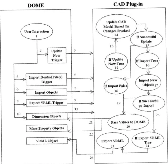
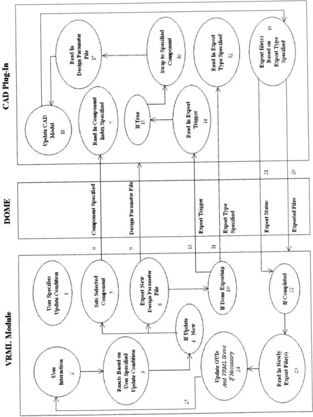
A schematic of the DOME CAD plug-in initialization process can be seen in Figure 2.7.
DONEE CAD Plug-in
Input Fi(e EXIt Parse Input File Couiec4 to CAD
C mm System Using Model
User Wfol Ilation
Specified
4
U-e Done
Parsiag-iput File Name) -( suwccs
[7e
Mdel Ifrmio 3 Obtain Objects
Specified By DOME
And Establish LinL~
Dimension bet 212
Ma Pope OVRtm Object
1 "S 1-Itt,(')j2
- Imost r Epoit Objects __
Expot VRML
VRML Object
Figure 2.7 CAD Plug-In Initialization Information Flow Diagram
Basically, once the CAD plug-in locates the user specified input text file, it will parse the file to extract the model information, design parameters, and file exchange requirements. The CAD server will then be connected to and the specified model file loaded into the active CAD session. The user specified modifiable dimension objects would then be located within the model file and the appropriate link established to allow the user to directly manipulate its value through the DOME graphic user interface (GUI). Any user specified design parameters that are invalid, such as incorrectly named in the user input file, will not be represented in the DOME GUI. If a VRML file was specified for the CAD model, then it will be exported from the CAD system.
After the CAD plug-in initializes properly and the DOME GUI is successfully created, a "<component>.txt" file will be generated. This file will contain assembly hierarchy information if the component selected for a DOME design session is an assembly. If the CAD plug-in user is a supplier who supplies his part to a heterogeneous CAD assembly designer, then he also needs to transfer this file to the assembly designer so she can properly create the "<component>.in" input text file if she wishes to utilize the DOME VRML module and traverse her supplier's assembly.
III.A. Exporting Components
A CAD designer can publish exported neutral file services over DOME. When an assembly designer subscribes to the CAD designer's service, the two designers can then begin designing a heterogeneous CAD assembly. In preparing his component for
Chapter 2: DOME CAD Plug-Ins 3737
integration into a heterogeneous CAD assembly, the CAD designer needs to first export his geometry in a format specified by the assembly designer and generate a text file containing density information related to his geometry. The geometry export process will need to be done manually. However, the density text file can be automatically generated for the designer through a program that runs external to DOME and is supplied along with DOME if the designer decides to forgo manually creating this text file.
To run this program, the CAD designer must have an active CAD session up and running and opened to the desired model file. The generated density file will then be placed in a specific directory, which resides as a subdirectory with the name "export" under the model directory, with the name "density.txt". The model directory is the directory under which the model file that DOME will interact with resides. If the "export" directory does not exist, it will be created by the executable application. Any and all subsequent exported files to be generated via a DOME session will be placed in this "export" directory as well.
Then, the CAD designer needs to transfer the exported neutral and density files over to the assembly designer. This is usually done outside of DOME. Once the assembly designer have received the exported files, have run a DOME supplied executable program that automatically extracts the neutral file into her CAD system and applies the appropriate density values to the solids based on data contained in the density text file, and have integrated the extracted components into her native assembly, she and the CAD designer can then start their DOME sessions and link their services to begin real-time design iterations.
During the design iteration process, it may become necessary for the CAD designer to supply the assembly designer with a modified neutral file. Rather than requiring the supplier to manually perform this operation, the CAD plug-in will recognize when this need arises and automatically compensates for it. That is, it will generate the updated neutral file when it knows it's required.
It should be noted here that the only allowable component that can be exported by the CAD designer during a DOME session is the top most component in his model hierarchy. For a single part component session, it is simply that part component. For an assembly component session, it is the entire assembly. However, the only exception comes in the export of assembly component VRML files for use in the DOME VRML module. This is to allow the assembly designer the ability to view all his DOME
components through the VRML module.
Initially, it was intended that when performing mass property calculations for a heterogeneous CAD assembly, only values calculated from original geometry would be used. That is, geometry from imported neutral files would not be used in order to avoid inaccuracies attributed to translator errors. However, due to limitations on the amount of information that is retained through neutral files, this preferred method could not be realized. In order for this method to work, several criteria need to be met.
First, mass property calculations about the center of mass must be made available through DOME to provide up to the minute values, which may change during a design iteration process. This is not a problem. Secondly, information regarding the location of the center of mass for that exported component about its local coordinate frame needs to be extracted and made available to the assembly designer. This is also not a problem.
Chapter 2: DOME CAD Plug-Ins 39
Third, and most importantly, the local coordinate frame of the exported component, once imported into the assembly designer's CAD system, must remain identical to its native system. This is where problems arise. While local coordinate frames are retained during an IGES export, they are not retained for a STEP export. Because the third criterion could not be met for all cases, a different method of approach need to be taken when dealing with calculating mass property values for a heterogeneous CAD assembly.
The chosen alternative method was already mentioned in the beginning of this section: make use of a density file for identifying which density value to apply to which component when it is imported into a different CAD system. The only catch to this method is that it requires a single part to be composed of a uniform material. However, with this solution, the geometry of the imported component would be utilized and that means there will be an error introduced into the mass property calculations dependent on the translation accuracy. The significance of those errors has yet to be determined in real test cases and is expected to decrease significantly with updates to the IGES and STEP standards.
Since density values also do not carry over in a neutral file, they need to be made available to the assembly designer somehow. It was decided that a text file, to be named "density.txt", would be the best method of conveying this information. This text file will contain information such as the name of the part component and its associated density value in the units of lb-in. An example density file for a camera assembly, which can be seen later in Figure 2.10, composed of three components (body, flash, and lens) can be seen in Figure 2.8.
Chapter 2: DOME CAD Plug-Ins 40
camera-body = 5.250000 cameraflash = 7.500000 camera lens = 9.850000
Figure 2.8 Sample "density.txt" file
An API program that functions independently of DOME has been developed to automatically generate this density file. This program requires that the user have his CAD system up and running and opened to the desired model file for export. The generated density file only needs to be accessed once during the initial startup of the heterogeneous CAD session. It is not expected that the material of the part component will ever change during a DOME session. Hence, the current process does not support the changing of material density for any imported components during a DOME session.
This API program does not export the component for the CAD designer, so the CAD designer is required to manually export her component the first time prior to transferring it to the assembly designer for incorporation into a heterogeneous CAD assembly. All subsequent export operations, once the appropriate DOME models are created, will be performed automatically through the DOME CAD plug-ins.
It should be noted here that depending on the CAD system, there might be instances that when dealing with an imported assembly, the names of the extracted part components differ from those in its native system. Different CAD systems have different ways of naming base components for an imported assembly, such as adding prefix and suffix to the original name of the part. Those patterns have been recognized and are accounted for by the CAD plug-ins. So, users do not have to worry about this issue.
When dealing with multiple imported files, all information pertaining to part densities need to be accumulated into a single density file. In this case, the assembly
designer will need to perform this operation manually. This is a very simple process and it only needs to be performed once. However, if during this process the assembly designer notices that several part components share a common name, then she must take steps to ensure that no two parts share the same original name (that is, its name within its native CAD model) by working with her suppliers.
Based on various issues encountered while developing the CAD plug-ins, it is heavily recommended that when working with an assembly that no two components ever share the same name regardless of its type, location, etc. Having two components share the same name can cause various problems to occur in the assembly and may lead to unpredictable results when running DOME. However, specific exceptions exist and they are mentioned in the individual plug-in sections.
It should be noted here that if it is the intention of the CAD designer to offer his neutral file service to an assembly designer working on a heterogeneous CAD assembly design, then he must inquire into whether the assembly designer will be working with the DOME VRML module. If the assembly designer will be working with the DOME VRML module, then the CAD designer must make sure that he also publish a VRML service and make it available to the assembly designer, along with additional files that the VRML module would require. He also needs to inform the assembly designer of the names of his subassembly components, if any, that contain design parameters publishable through DOME so those components can be traversed through the assembly tree within the VRML module. These extra steps are necessary due to how the VRML module operates and details about these requirements will be presented in the next chapter.
42 Chapter 2: DOME CAD Plug-Ins
III.B. Importing Components
For the assembly designer working with imported neutral files, an initial import preparation process is required when she brings the imported components into an assembly for the very first time. An API program that functions independently of DOME was developed to automatically perform this initial import operation and prep the extracted components. Subsequent import operations during an active DOME session will be performed automatically by the CAD plug-ins.
The import program runs external to DOME and will extract all imported files into the appropriate directory or bin depending on which CAD system the files are intended for. The exported files, that need to be extracted for incorporation into the assembly, must be placed in the "import" subdirectory under the model directory. If this directory does not already exist, the assembly designer needs to create it. Into this directory must also be placed the "density.txt" and "import.txt" files. The purpose of the "density.txt" file was explained in the previous section. The purpose of the "import.txt" file will be explained shortly.
If the assembly designer is dealing with neutral files from several suppliers, all density files must be consolidated into a single density file containing the sum of all information. If repeated component names are discovered, steps must be taken to ensure that no two components ever share the same original name.
The purpose of the "import.txt" file is to inform the import program of the names of the files residing in the import directory that needs to be extracted for incorporation into the assembly. This provides the assembly designer with the flexibility of selecting
43 Chapter 2: DOME CAD Plug-Ins