HAL Id: hal-00711320
https://hal.archives-ouvertes.fr/hal-00711320
Submitted on 23 Jun 2012
HAL is a multi-disciplinary open access
archive for the deposit and dissemination of
sci-entific research documents, whether they are
pub-lished or not. The documents may come from
teaching and research institutions in France or
abroad, or from public or private research centers.
L’archive ouverte pluridisciplinaire HAL, est
destinée au dépôt et à la diffusion de documents
scientifiques de niveau recherche, publiés ou non,
émanant des établissements d’enseignement et de
recherche français ou étrangers, des laboratoires
publics ou privés.
Investigations on Noise Processes in Optical Resonator
Based Microwave Oscillators
Khaldoun Saleh, Pierre-Henri Merrer, Olivier Llopis, Gilles Cibiel
To cite this version:
Khaldoun Saleh, Pierre-Henri Merrer, Olivier Llopis, Gilles Cibiel. Investigations on Noise Processes in
Optical Resonator Based Microwave Oscillators. European Microwave Integrated Circuits Conference
(EuMIC), Oct 2012, Amsterdam, Netherlands. pp.975-978. �hal-00711320�
Investigations on Noise Processes in Optical
Resonator Based Microwave Oscillators
Khaldoun Saleh
1,2,3, Pierre-Henri Merrer
1,2, Olivier Llopis
1,2and Gilles Cibiel
31CNRS; LAAS, 7 Avenue du Colonel Roche, F-31077 2Université de Toulouse; UPS, F-31077 3CNES, 18 Avenue Edouard Belin, F-31401
Toulouse, France [email protected]
Abstract— Optoelectronic oscillators based on high Q optical
resonators are presented in this paper. These oscillators use a Pound-Drever-Hall laser stabilization technique and two different types of resonators: fiber ring and monocrystalline disk resonators. Noise processes in the oscillators are discussed, particularly the influence of the laser noise conversion and nonlinear optical scattering noise. A modeling approach using CAD software is also proposed.
Keywords- optoelectronic oscillators; microwave photonics; fiber ring resonators; whispering gallery mode resonators; phase noise
I. INTRODUCTION
Microwave oscillators based on optical frequency references have become quite common, at least the ones based on fiber optics spools which have been studied since 1994 [1]. These optoelectronic oscillators (OEOs) take benefit of the ultra-low losses in silica fibers, and thus of the large delay provided by long fibers in the kilometer range. This large delay is equivalent to a high microwave quality factor (QRF), and Q factors higher than 106 can be reached at an application frequency of 10 GHz. However, these delay line OEOs suffer from different drawbacks which are the fiber spool size, making the system hard to stabilize in temperature, and the spurious modes generation. Many approaches have been proposed to solve these problems, but they still quite complex and the system remains bulky.
An alternative solution instead of using delay lines in OEOs, is the use of optical resonators [2], [3]. Optical quality factors (Qopt) as high as 108 to 1011 may be obtained with different types of optical resonators: fiber ring resonators (FRRs), monocrystalline disks, silica spheres or toroids, Fabry-Perot ultra stable cavities… Using these optical resonators, the equivalent microwave quality factor is linked to the optical quality factor by the relation below:
opt RF opt RF
f
f
Q
Q
=
×
(1)where fRF and fopt are respectively the microwave (RF) and the optical frequencies.
From (1) we can see that interestingly, and unlike microwave resonators, the equivalent QRFs of these optical
resonators increase while increasing the RF application frequency fRF. As an example, a Qopt factor of 109, at 1.55 µm wavelength (~ 200 THz), results in an equivalent QRF factor of 105 at 20 GHz. This is lower than the equivalent QRF factor of a long delay line but still particularly interesting if compared to the QRF factor of conventional microwave resonators, taking also into account the reduction in system size if we replace the delay line by a resonant device.
A special case of resonant or regenerative OEOs is the coupled OEO (COEO) [4], in which a microwave oscillator is coupled to an optical oscillator. Like the resonator approach, the COEO allows a reduction in the fiber length, while keeping high performances. The advantage of the COEO relies in the fact that the laser and the resonator are the same device. However, system size and Qopt factor could be better in passive resonator based OEOs, if problems of noise conversion and laser stabilization can be efficiently resolved.
In this paper, noise processes in OEOs based on either FRRs or tridimensional monocrystalline resonators are discussed. All these OEOs use the same system to stabilize the laser onto the resonator: a Pound Drever Hall (PDH) technique [5]. Some noise processes are studied theoretically, especially those related to the laser amplitude (AM) and frequency (FM) noise conversion, thanks to a system design approach developed on Agilent ADS microwave software. Experimental results are also provided.
II. RESONATOR BASED OPTELECTRONIC OSCILLATOR
The OEOs described in this paper are based on ultra-high Qopt optical resonators featuring a comb of resonances with microwave spacing called free spectral range (FSR). The resonator FSR must be a sub-multiple of the application frequency. In this case, the beat note between two or three optical modes of the resonator will be used in the microwave domain. Before setting up the filtering of the microwave signal, it is necessary to stabilize the laser carrier on one of the modes of the resonator. The extreme Qopt factors of these resonators make them very sensitive to the incident light power. When the light wave is resonant inside the resonator, the circulating intra-cavity power can be as high as 54 times the incident light power, depending on the resonator Qopt factor. This induces a strong thermal effect [6], which shifts the optical resonance and the resonator is no more coupled to the laser unless a feedback
system is used to maintain the laser at the resonance frequency. Also, the high circulating intra-cavity power can lead to the generation of many nonlinear optical effects inside the resonator, as we will see later in section IV.
Many feedback approaches can be used to stabilize the laser to the resonance frequency. First, using whispering gallery modes (WGM) disks or sphere resonators, one can take benefit of a natural counter-rotating wave inside the resonator to optically lock the laser to the resonator [7]. Of course, this requires an accurate control of the resonator-laser distance. A self-thermal lock can be also realized in some cases, depending on the thermal expansion parameters of the resonator, but such a lock process is not reliable enough for all applications. The approach we have chosen, the PDH technique, is based on an electrical feedback to the laser: the phase transition at the resonance is converted into an error signal and fed-back to control the laser frequency. This approach is very reliable in time and it can be applied to any laser having a linewidth smaller than the resonance linewidth and on which a frequency control parameter is available.
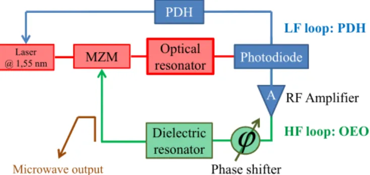
The OEO system is depicted in Fig. 1. The laser is first locked to the resonator thanks to a PDH low frequency (LF) loop and then the microwave oscillation is started thanks to a high frequency (HF) loop. The HF loop includes a RF amplifier, a phase shifter and, in the case of FRR, a mode selection filter, because we use a 20 meter long FRR that features a 10 MHz FSR. This is not the case of the WGM disk resonator, which is of millimeter size and thus its resonant comb features a FSR higher than 12 GHz. For OEOs based on WGM resonators, the microwave filter is thus useless.
PDH Optical resonator MZM Photodiode Dielectric resonator
ϕ
Laser @ 1,55 nm Microwave output LF loop: PDH HF loop: OEO A Phase shifter RF AmplifierFigure 1. OEO setup based on a PDH loop to stabilize the laser and a HF loop to maintain the microwave oscillation; PDH: Pound Drever Hall, MZM: Mach-Zehnder modulator.
III. FIBER RING AND WGMOPTICAL RESONATORS
The above OEO system has been firstly set up with a FRR [8]. The resonator is realized with two low loss fibered directional couplers with low coupling factors (about 1%) linked with an optical fiber of a few meters, Fig. 2. As an example, we have been able to obtain a Qopt factor of 5.1x10⁹ with a 20 meter long FRR. It is a relatively small device (planar device) featuring an equivalent QRF factor of 5.1x10⁵ at 20 GHz, which is above conventional microwave resonators QRF factors. This FRR’s Qopt factor is very similar to Qs of WGM disk resonators, and the first goal in using this fibered resonator was to set up an OEO system which would be compatible with WGM resonators in order to study them
accurately. However, the performances of the FRR are already very interesting. Also, it is much easier than WGM resonators to set up, thanks to the well-established technology of fibered directional couplers.
The other types of resonators we have studied are WGM silica spheres and calcium fluoride CaF2 polished disk resonators, Fig. 2. These resonators are coupled to the laser thanks to tapered fibers and a Nano-scale positioning system. This coupling system is very efficient, but it remains a laboratory experiment system. We have obtained Qopt factors in the range of 108 both on silica spheres and CaF
2 disks. Qopt as high as 1011 have already been demonstrated with CaF
2 disks [3]. C1 C2 Splices Output 1 (absorption) Input Laser
(transmission) Output 3 Output 2 (transmission)
2ndStokes 2ndStokes
1stStokes
Laser 1stStokes
Laser
Figure 2. A 20m long fiber ring resonator (left) and a 5.5 mm whispering
gallery modes CaF2 resonator (right).
IV. NOISE IN A RESONATOR BASED OEO
Unlike microwave oscillators, in which phase noise is dominated by RF amplifiers noise, the phase noise in OEOs is generally dominated by noise processes occurring in the optical part of the system. This is even more true for resonator based OEOs, in which the required correlation between the laser and the resonance frequency may induce specific noise processes. Also, the resonator ultra-high Qopt factor may lead to an induced nonlinear optical scattering noise inside the resonator, converted into microwave phase noise in the OEO setup.
Two types of laser noise conversion processes are particularly important: the laser AM and FM noise conversion. Because the photodiode performs amplitude detection, it is obvious that the laser AM noise may have an influence on the microwave phase noise. Also, this is generally the parameter which determines the signal to noise ratio (unless there are too much losses through the resonator) and thus the OEO phase noise far from the carrier. However, for most applications, the close to the carrier phase noise performance (1 Hz to 10 kHz) is the most critical parameter. At these offset frequencies, a 1/f like frequency noise is observed.
To determine the ratio of laser AM and FM noise conversion into RF phase noise, a modeling approach has been set up using Agilent ADS microwave software. This approach takes benefit of the harmonic balance technique provided by ADS to describe the nonlinear signal and noise conversion processes occurring between the laser frequency (~200 THz), the microwave frequency and the DC. Because ADS does not include models for optical devices, we have developed our own models, which are either based on equivalent circuit descriptions or on mathematical black box descriptions. As an example, the laser is described with a classical frequency source with its FM noise, and an amplitude modulator is added to model the laser AM noise.
Fig. 3 depicts the model used for the resonator. In this case, a FRR was modeled and described using modified models of ideal lines and coupled lines of ADS. The resonant comb, the FSR and the Qopt factor are accurately described with this approach on any of the four ports of this resonator and simulation results fit very well with our experimental measurements data. One of the advantages of such ADS resonator model is the capability of easily simulating very complex scheme based on multiple optical resonators.
S_Param G21 Step=0.001 MHz Stop=200.0000001 T Hz Start=199.9999999 T Hz S-PARAMETERS CLINP TL20 CLINP T L21 PhaseShiftSML PS2 Attenuator AT TEN6 T LINP T L24 T LINPT L23 T erm T erm1 Z=50 Ohm Num=1 Term Term3 Z=50 Ohm Num=3 Term Term4 Z=50 Ohm Num=4 Term Term2 Z=50 Ohm Num=2
Figure 3. FRR model using ADS, and S21 amplitude simulation results.
For our OEO application and noise investigations, an interesting study which can be performed on ADS is on the way the optical modes are translated into electrical resonances in a system including: laser + modulator + optical resonator + photodiode. If a classical Mach-Zehnder linear modulation is used (Vbias = V/2), the modulated laser carrier features two optical sidebands which simultaneously go through two lateral modes of the resonator. This process gives birth to a unique microwave mode at the photodiode output, which results from the two optical modulation sidebands and the laser carrier folded one onto the other.
-16 -14 -12 -10 -8 -6 -4 -2 0 2 4 6 8 10 10,18286 10,18303 10,1832 10,18337 10,18354 S2 1 M ag n it ud e (d B ) Frequency (Hz) S21 Magnitude - Left S21 Magnitude - Center S21 Magnitude - Right -180 -160 -140 -120 -100-80 -60 -40 -200 20 40 60 80 100 120 140 10,18286 10,18303 10,1832 10,18337 10,18354 S 21 P h as e (° ) Frequency (Hz) S21 phase - Left S21 Phase - Center S21 phase - Right -40 -35 -30 -25 -20 -15 -10 -5 0
1,01968E+10 1,01970E+10 1,01972E+10 1,01974E+10
S 21 M A gn itu d e (d B ) Frequency (Hz) S21 Magnitude - Left S21 Magnitude - Center S21 Magnitude - Right -140,00 -120,00 -100,00 -80,00 -60,00 -40,00 -20,00 0,00 20,00 40,00 60,00 80,00 100,00 120,00
1,01968E+10 1,01970E+10 1,01972E+10 1,01974E+10
S21 P h as e (° ) Frequency (Hz) S21 phase - Left S21 Phase - Center S21 phase - Right Experiment ADS
Figure 4. S21 RF amplitude and phase responses through modulator + optical
resonator + photodiode; Experimental and ADS simulation results. Case of a laser perfectly centered on the mode (red curve) and of a shift between the laser frequency and the resonator frequency (blue and green curves).
If the laser is perfectly centered on one of the modes, and the two lateral sidebands are identical, then a microwave mode identical to the optical modes of the comb (same 3 dB bandwidth and phase slope) is observed in the microwave domain. However, if the laser is not perfectly centered, the
phase slope of the microwave signal (and thus the QRF factor) is reduced, as it can be seen from the simulation results in Fig. 4. Moreover, if the laser is not at the center of the resonance, the system becomes sensitive to laser frequency fluctuations, and thus it is able to convert the laser phase noise into electrical phase and amplitude noise. This simulation demonstrates how important is the laser lock and the ability to control this locking process. Such a possibility is well provided by the Pound-Drever-Hall approach.
Another problem in these systems relies on the starting up of optical nonlinear processes inside the resonator due to the high circulating intra-cavity power. This will also degrade the microwave phase noise. The two main processes to be considered are Rayleigh and Brillouin scatterings. We have experimentally found that the stimulated Brillouin scattering (SBS) process occurs at relatively low input power in these resonators, at least in the case of FRR [9], depending on its Qopt factor. Once this process starts, a Brillouin (back-reflected) Stokes wave downshifted in frequency from the laser carrier by about 10.8 GHz (for silica fibers) can be observed. Using a 20m long FRR, and because of the high circulating intra-cavity power, we have been able to detect the generation of the seventh order Brillouin line at 10 dBm of optical input laser power, Fig. 5. This parasitic signals mix either inside the resonator (they modulate the amplitude of the main signal) or at the photodiode level with the main signal, thus increasing the RF phase noise, especially close to the carrier.
-55 -52 -49 -46 -43 -40 -37 -34 -31 -28 -25 -22 -19 -16 -13 1549,33 1549,48 1549,63 1549,78 1549,93 1550,08 1550,23 1550,38 1550,53 Po we r ( dB m ) Wavelength (nm) (-10 dBm) (-8 dBm) (-6 dBm) (-4 dBm) (-2 dBm) (0 dBm) (2 dBm) (4 dBm) (6 dBm) (8 dBm) (10 dBm)
Figure 5. Stimulated Brillouin scattering lines generation inside a 20m long
fiber ring resonator with a Qopt factor of 3.5x10⁹.
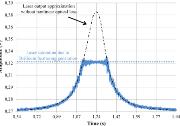
The Brillouin scattering generation also leads to nonlinear losses inside the resonator which will be added to the resonator intrinsic loss. After being generated, above the SBS threshold, the Brillouin scattering converts any additional laser power injected above this threshold to its own power and generates other Brillouin lines (Fig. 5). This will cause laser carrier depletion, and thus it leads to the degradation of the noise to carrier ratio of the optical link. Fig. 6 shows the DC detection of the photodiode at the resonator third output using an oscilloscope, where we can clearly notice the saturation in the detected signal while the laser frequency is scanning a resonance line of the resonator and when its injected power inside the resonator starts to be above the SBS threshold.
Therefore, a good performance close to the carrier can only be obtained at low optical input power, unless a specific set up can reduce the onset of these processes, while maintaining a high Qopt. This could be possible if optical fibers of different materials are used together (different Brillouin gain frequencies, thus a reduced global Brillouin gain), or if the fiber material is locally changed (thermally or mechanically), and also when changing the fiber structure (e.g. increasing its core diameter…). 0,27 0,28 0,29 0,31 0,32 0,34 0,35 0,36 0,38 0,39 0,54 0,72 0,89 1,07 1,24 1,42 1,59 1,77 1,94 A m plit ude ( V ) Time (s)
Laser saturation due to Brillouin Scattering generation
Laser output approximation without nonlinear optical loss
Figure 6. Visible laser carrier saturation, due to the Brillouin scattering generation, by measuring the photodiode DC voltage at the resonator third output, while the laser frequency is scanning a resonance line.
V. OEOPHASE NOISE MEASUREMENTS
Fig. 7 depicts the measured phase noise of a 10.2 GHz OEO realized with a FRR featuring a Qopt factor of 3.5x10⁹ (equivalent QRF = 1.8x10⁵) [9], and of a 12.5 GHz OEO realized with a CaF2 disk resonator featuring a Qopt factor of 1.4x10⁸ (equivalent QRF = 9x10³). Compared to microwave oscillators having same QRF factors, these two oscillators feature a higher phase noise. This is due to the optical noise contribution which is still not completely optimized in spite of taking into account the remarks of paragraph IV. The peaks in
the phase noise of the CaF2 disk OEO may come from
mechanical perturbations in the coupling using tapered fibers.
-140 -130 -120 -110 -100 -90 -80 -70 -60 -50 -40 -30 -20 -10 0
1,00E+01 1,00E+02 1,00E+03 1,00E+04 1,00E+05 1,00E+06 1,00E+07
Pha se no is e ( dB c/ H z) Frequency (Hz) 12,5 GHz – CaF2 WGM OEO 10,2 GHz FRR-OEO
Figure 7. Phase noise of OEOs realized with a CaF2 resonator (12.5 GHz)
and a 20 meter long fiber ring resonator (10.2 GHz). Measurements are performed with an Agilent E5052 B signal source analyzer.
Work is in progress to reduce these contributions, particularly in the case of the FRR in which solutions exists to remove some of the nonlinear optical effects. In the case of the disk resonator, attempts to improve the phase noise will be first based on an improvement of the resonator Qopt factor.
VI. CONCLUSION
Noise in optoelectronic oscillators based on fiber ring and whispering gallery modes resonators has been studied in this paper. It has been confirmed through theoretical and experimental studies that the phase noise in these OEOs is generally dominated by noise processes occurring in the optical part of the system. In resonator based OEOs, a correlation between the laser and the resonator frequency is required and a specific laser AM and FM noise conversion processes may be induced if this condition is not respected. Also, the high optical Q factors of these resonators can lead to the generation of some nonlinear optical scattering effects at low laser input optical power. Working at low enough optical power is mandatory in order to avoid this noise type and to get a good OEO phase noise. Further investigations include the design of new high Q optical resonators, immunized against nonlinear optical effects.
ACKNOWLEDGMENT
This study is part of a French National Research Agency (ANR) project ORA (2010 BLAN 0312 03).
REFERENCES
[1] X.S. Yao, D. Eliyahu, L. Maleki, “Progress in the optoelectronic oscillator – a ten year anniversary review,” IEEE Microwave Theory and Tech. Symp. Digest, vol. 1, pp. 287-290, Jun. (2004).
[2] L. Maleki, X.S. Yao, J. Yu, V. Ilchenko, “New schemes for improved opto-electronic oscillator,” Int. Topical Meeting on Microwave Photonics, MWP99, pp. 177, Nov. (1999).
[3] A. A. Savchenkov, A. B. Matsko, V. S. Ilchenko, and L. Maleki, "Optical resonators with ten million finesse," Opt. Express 15, 6768-6773 (2007).
[4] B. Matsko, D. Eliyahu, P. Koonath, D. Seidel, and L. Maleki, "Theory of coupled optoelectronic microwave oscillator I: expectation values," J. Opt. Soc. Am. B 26, 1023-1031 (2009).
[5] R. W. P. Drever, J. L. Hall, F. V. Kowalski, J. Hough, G. M. Ford, A. J. Munley, et H. Ward, “Laser phase and frequency stabilization using an optical resonator”, Applied Physics B, vol. 31, no. 2, pp. 97-105, June (1983).
[6] T. Carmon, L. Yang, and K. Vahala, "Dynamical thermal behavior and thermal self-stability of microcavities," Opt. Express 12, 4742-4750 (2004).
[7] L. Maleki, J. Byrd, A. A. Savchenkov, W. Liang, V. S. Ilchenko, D. Seidel, A. B. Matsko, “On the Development of Photonic RF Oscillators and Resonant Electro-Optic Modulators for Advanced RF Front-End Applications”, 2011 IEEE IMS Symposium Digest, pp. 1-4, Baltimore, June (2011).
[8] P. H. Merrer, A. Bouchier, H. Brahimi, O. Llopis, and G. Cibiel, "High-Q Optical Resonators for Stabilization of High Spectral Purity Microwave Oscillators", proc. of the 2009 IEEE EFTF-IFCS, pp. 866– 869, (2009).
[9] K. Saleh, P. Merrer, O. Llopis, and G. Cibiel, "Optical scattering noise in high Q fiber ring resonators and its effect on optoelectronic oscillator phase noise," Opt. Lett. 37, 518-520 (2012).