Casting inorganic structures with DNA molds
The MIT Faculty has made this article openly available.
Please share
how this access benefits you. Your story matters.
Citation
Sun, W., E. Boulais, Y. Hakobyan, W. L. Wang, A. Guan, M. Bathe, and
P. Yin. “Casting Inorganic Structures with DNA Molds.” Science 346,
no. 6210 (October 9, 2014): 1258361–1258361.
As Published
http://dx.doi.org/10.1126/science.1258361
Publisher
American Association for the Advancement of Science (AAAS)
Version
Author's final manuscript
Citable link
http://hdl.handle.net/1721.1/99234
Terms of Use
Creative Commons Attribution-Noncommercial-Share Alike
Casting inorganic structures with DNA molds
Wei Sun1,2, Etienne Boulais3, Yera Hakobyan3, Wei Li Wang1,2, Amy Guan1, Mark Bathe3,*, and Peng Yin1,2,*
1Wyss Institute for Biologically Inspired Engineering, Harvard University, Boston, MA 02115, USA 2Department of Systems Biology, Harvard Medical School, Boston, MA 02115, USA
3Department of Biological Engineering, Massachusetts Institute of Technology, Cambridge, MA
02139, USA
Abstract
We report a general strategy for designing and synthesizing inorganic nanostructures with arbitrarily prescribed three-dimensional shapes. Computationally designed DNA strands self-assemble into a stiff “nano-mold” that contains a user-specified three-dimensional cavity and encloses a nucleating gold “seed”. Under mild conditions, this seed grows into a larger cast structure that fills and thus replicates the cavity. We synthesized a variety of nanoparticles with three nanometer resolution: three distinct silver cuboids with three independently tunable dimensions, silver and gold nanoparticles with diverse cross sections, and composite structures with homo-/heterogeneous components. The designer equilateral silver triangular and spherical nanoparticles exhibited plasmonic properties consistent with electromagnetism-based simulations. Our framework is generalizable to more complex geometries and diverse inorganic materials, offering a range of applications in biosensing, photonics, and nanoelectronics.
Synthesis of shape-controlled inorganic structures underlies diverse applications in biosensing (1), light harvesting (2), and nanophotonics (3). Although a wide variety of synthetic nanostructures have been reported, the formation of nanoparticles (NPs) with arbitrarily prescribed three-dimensional (3D) shape and positional surface modification of sub-5 nm resolution has not been demonstrated with inorganic materials. Top-down lithography (e.g., electron beam lithography) has limited resolution, particularly for 3D shapes (1, 4). In addition, it is a slow serial process, and therefore unsuitable for large-scale production. Capping ligands can be used to tune the energy difference of selected
crystallographic facets and hence NP growth dynamics to produce diverse symmetric shapes (5–11). However, reliable dynamic growth simulation models are typically limited to highly
*Corresponding author: [email protected] (P.Y.); [email protected] (M.B.).
Supplementary Materials
www.sciencemag.org/cgi/content/full/science.1258361/DC1 Materials and Methods
Supplementary Text
NIH Public Access
Author Manuscript
Science. Author manuscript; available in PMC 2015 May 07.
Published in final edited form as:
Science. 2014 November 7; 346(6210): 1258361. doi:10.1126/science.1258361.
NIH-PA Author Manuscript
NIH-PA Author Manuscript
symmetric shapes of identical surface facets (11–14), and it is challenging to predict irregular shapes as well as control final NP dimensions.
Structural DNA nanotechnology (15) provides a promising route to overcoming the preceding limitations. Using DNA molecules as construction materials, researchers have rationally designed and synthesized diverse shape-controlled nanostructures (16–28). Building on this success, we have developed a general framework to program 3D inorganic shapes (fig. S1) (29). Our approach uses computationally designed, chemically stable, and mechanically stiff DNA nanostructures as molds to cast metallic NPs of user-specified 3D shape, which can be asymmetric. A “nanomold” is self-assembled from DNA strands, contains the user-designed 3D cavity, and encloses a small nucleating gold (Au) seed. Under mild conditions, the Au seed grows into a larger metal cast NP that fills the entire cavity of the mold, thereby replicating its 3D shape.
Using this nanocasting method, we constructed three distinct sub-25 nm 3D cuboid silver (Ag) NPs with three independently tunable dimensions. The shape versatility of DNA based nanocasting was further demonstrated via the synthesis of Ag NPs with equilateral
triangular, right triangular, and circular cross sections. Material versatility was demonstrated via synthesis of a Au cuboid in addition to the Ag NPs. The DNA mold served as an addressable coating for the cast NP and thus enabled the construction of higher order composite structures, including a Y-shaped Ag NP composite and a quantum-dot (QD)-Ag-QD sandwiched structure. Finally, the designer equilateral Ag triangle and Ag sphere exhibited plasmonic properties that are consistent with electromagnetism-based simulations. By serving both as an informational “genome” to carry the user-designed blueprint of the inorganic shape in a digitally precise fashion and as a physical “fabricator” for its faithful and accurate execution, DNA enables a new kind of shape-by-design framework for inorganic nanostructure fabrication and promises diverse transformative applications. For example, because the plasmonic properties of shape-controlled metal NPs can be predicted quantitatively in silico, the current shape-by-design framework can be further generalized to be a property-by-design framework for producing inorganic nanostructures with prescribed functional properties.
Casting a Ag cuboid
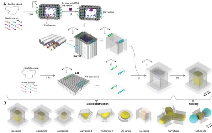
Figure 1A depicts the process of casting a cuboid shaped Ag NP. First, we construct a DNA mold for the casting (steps 1–3). In steps 1a and 1b, an open-ended DNA nanostructure barrel and two DNA lids are respectively designed and assembled based on computed stiffness design. In step 2, a 5 nm Au NP is anchored to the interior surface of the barrel. In step 3, the attachment of the two lids to the barrel results in a box-like DNA mold with a cuboid cavity. At the end of step 3, we have constructed a DNA mold with a cuboid cavity and a Au seed inside. With this mold, in step 4 (the casting step), under suitable chemical conditions, the Au seed grows into a Ag NP confined by the mold. Using this strategy and its variants, we fabricated diverse shape controlled NPs (Fig. 1B). We next describe the design and construction details for casting a Ag cuboid NP using the afore-mentioned strategy (Fig. 1A).
NIH-PA Author Manuscript
NIH-PA Author Manuscript
Computational design of the DNA mold
Specifically, to design mechanically stiff molds for geometrically constrained metal growth in solution, we used scaffolded DNA origami (22), which enables the precise nanometer-scale design of complex 3D cavities of prescribed mechanical properties. The DNA sequences for the DNA mold were designed using software caDNAno (30), and its mechanical ground-state 3D solution structure and mechanical properties were then predicted by CanDo (31, 32). Briefly, CanDo computes 3D solution structure by modeling B-form DNA as a continuous elastic rod with effective geometric and material properties. Crossovers are assumed to rigidly constrain adjacent helices on a square or honeycomb lattice. Effective mechanical properties of the molds, including their ground-state solution structures and their mechanical deformations in response to loading forces, are computed using the finite element method (29).
We first designed a multilayer DNA mold with a cuboid cavity. The sidewalls of the DNA mold were designed to possess two or three layers of parallel DNA helices with 12 crossovers per helix on average (Fig. 1A). Two to three layer sidewall thickness was selected to balance the competing needs to optimize structural stiffness and to increase the cavity dimensions: thicker sidewalls result in higher structural stiffness but smaller cavity size, owing to the length limit of the scaffold strand (8,064 nucleotides). The x-y cross section of the central cavity was designed to be eight helices by six helices, with a
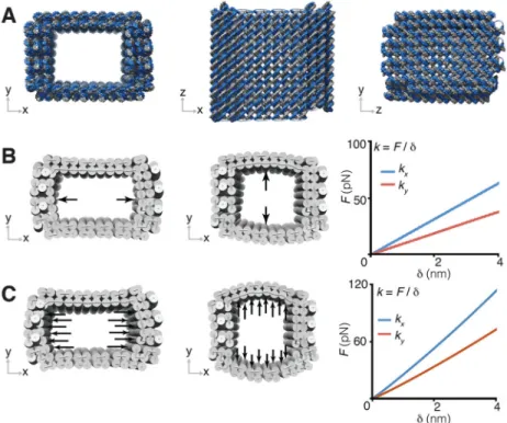
z-dimensional height of nine helical turns. This provides a designed cuboid cavity (after the lid attachment in step 3) measuring 21 nm by 16 nm by 31 nm, assuming a 2.6 nm hydrated helix width and a 3.4 nm helical turn length (33). Simulation by CanDo verified that the ground-state solution structure of the DNA mold adopted the cuboid shape cavity (Fig. 2A and fig. S4A). We additionally examined the structural integrity of the mold using normal mode analysis (29).
To effectively confine metal growth, it is important that the DNA mold be sufficiently stiff. We therefore studied its response to different loading forces along the x- and y-direction (Fig. 2, B and C). The ground-state structure of the cuboid mold was used as the initial configuration to which two types of loading were applied to model distinct types of mechanical inhibition from the mold onto a given growing NP, namely point-contact (fig. S2) or distributed-contact (fig. S3). In the point-contact model, a growing NP is assumed to contact a single pair of directly opposing points of the mold (Fig. 2B and table S1, top); equal and opposite point forces are applied to the mold and its deformation is computed. In the distributed-contact model, a growing NP is assumed to fully fill the mold cavity so that the NP applies a uniformly distributed force along opposing interior walls of the cavity (Fig. 2C and table S1, bottom). Under the point-contact scenario, the force response for the barrel was 17 pN/nm in the x-direction, normal to the three-layer wall, and 10 pN/nm in the y-direction, normal to the two-layer wall. In comparison, higher force-response values were found for the distributed-contact scenario, around 30 pN/nm in the x-direction, normal to the three-layer wall, and 19 pN/nm in the y-direction, normal to the two-layered wall.
Importantly, the simulated mechanical properties of the DNA mold (i.e., threshold force and linear deformation range) were found comparable to that of viral capsids (34) which have been used to effectively confine inorganic nano-materials grown within (35) [see (29) for
NIH-PA Author Manuscript
NIH-PA Author Manuscript
calculation and comparison details]. This result suggests that the DNA mold is also sufficiently stiff to confine metal NP growth within, although growth expansion forces can produce slightly increased [up to 20% according to simulation; (29)] mold dimensions through elastic deformation of dsDNAs. Notably, mold stiffness was significantly affected by the sidewall thickness. Mechanical simulation revealed that the force response value increased seven-fold from one to three layers under the point-contact loading scenario (see tables S1, S4, and S5).
Design details
The above computation suggests that (1) our designed DNA mold has the expected ground-state solution conformation and that (2) it has sufficient mechanical stiffness to confine metal NP growth. Thus we used this design for step 1a. In step 1b, a three-layered DNA lid was designed with 18 helices in the y-direction, three helices in the z-direction and 13-helical turns in the x-direction (Fig. 1A).
In step 2, to attach the Au “seed” to the DNA barrel (36), twenty-seven 21-nucleotide (nt) single-stranded (ss) DNA “handles” were immobilized in the interior surface of the barrel (Fig. 1A). A 21-nt “anti-handle” (an ssDNA with sequence complementary to the handle) was immobilized onto the Au seed surface. The stoichiometric ratio between the anti-handle and the Au seed was set at 1:1 to achieve approximately one anti-handle per seed based on a previous report (37). The hybridization between the handle and the anti-handle anchored the Au seed to the interior of the barrel. Au seed was favored over Ag seed due to the stability and nucleation versatility of Au (38–41).
To assemble the seed-decorated barrel and the lids in step 3, the barrel was designed to carry fourteen and sixteen 16-nt ssDNA “connectors” on both ends (fig. S28, left), and one side of the lid was designed to carry twenty complementary “connectors”. Connectors and anti-connectors were designed to be positioned in roughly matching patterns. Hybridization between them brought the barrel and the two lids together, completing the assembly of a box-like mold with a fully enclosed cuboid cavity. The ~0.5 nm gap between neighboring DNA helices (not depicted in the figure) that comprised the mold was expected to permit the diffusion of small ions or molecules, such as metal ions and ascorbic acid, into the enclosed box. In step 4, under suitable chemical conditions (see details in the following paragraph), the Au seed would grow into a Ag cuboid that fills the cavity.
Experimental implementation
In a typical experiment, DNA barrels and lids were folded separately by slowly annealing the staple/scaffold mixtures from 80°C to 24°C over 72 hours. Crude products were subjected to 1.5% agarose gel electrophoresis with 0.5× TBE/10 mM Mg(NO3)2 as running
buffer. Purified structures were extracted and subsequently recovered via centrifugation. Seed decoration was executed by incubating DNA barrels with 5-nm Au NPs (at a seed-to-barrel stoichiometry ratio of 2:1) at 35°C for 16 hours, and then annealed to 24°C over 3 hours. Excess Au seeds were removed by using a size-exclusion spin column. DNA lids were mixed with the seed-decorated DNA barrels (at lid-to-barrel stoichiometry ratio of 3:1) at 35°C for 16 hours, and annealed to 24°C over 3 hours. Growth of Ag NPs in step 4 was
NIH-PA Author Manuscript
NIH-PA Author Manuscript
triggered by the addition of silver nitrate (1.4 mM) and ascorbic acid (2 mM). After growth for 10 min at room temperature in dark conditions, Ag NPs grown within DNA boxes were imaged by transmission electron microscopy (TEM). See (29) for experimental details of mold assembly and purification, metal growth, and TEM sample preparations.
TEM characterization
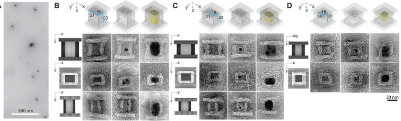
TEM imaging confirmed successful formation of barrels in step 1a (see fig. S23 for large-field-of-view images), formation of the lids in step 1b (see fig. S30 for large-large-field-of-view images), attachment of Au seed to the barrel in step 2 (see fig. S39 for large-field-of-view image), assembly of lids with the seed-decorated barrel in step 3 (Fig. 3B, middle column; see fig. S47 for large-field-of-view images), and finally formation of Ag cuboids with expected dimensions in step 4 (Fig. 3A; Fig. 3B, right column; see fig. S52 for large-field-of-view images). In a supporting experiment, lids also assembled successfully with a seed-free barrel (Fig. 3B, left).
From three projectional views of the TEM images (Fig. 3B, left column), the x-y, x-z, and
y-z dimensions of the barrel cavity were measured respectively as 19.3 ± 1.5 nm by 13.3 ± 0.4
nm, 19.3 ± 1.5 nm by 30.5 ± 1.0 nm, and 13.3 ± 0.4 nm by 30.5 ± 1.0 nm (N = 20 for each projectional view), each approximately consistent with the designed 21 nm by 16 nm by 30 nm cuboid cavity enclosed in the box. From the x-y projection TEM image (Fig. 3B, middle row), thickness of top and bottom side-walls of the barrel were measured to be 5.6 ± 0.2 nm (N = 20) while the left and right sidewalls were measured to be 7.8 ± 0.1 nm (N = 20, similar measurements were also obtained from x-z and y-z projections), which were in approximate agreement with two- or three-layered designs. However, due to partial dehydration and structural deformation during TEM sample preparation, small deviations of 2–3 nm were occasionally observed in some structures. The DNA lid exhibited designed 39.5 ± 2.6 nm by 47.7 ± 0.7 nm (N = 20) dimensions under TEM (see fig. S30 for large-field-of-view images). Because the barrel was designed to carry 27 handles, multiple seeds could in principle be attached to the barrel; here, we experimentally observed one–five seeds present in a single barrel (Fig. 3B, middle column; see fig. S39 for large-field-of-view images).
After growth, the seed turned into a Ag cuboid, as revealed by the TEM images of dark rectangular projections in the x-z, x-y, and y-z planes, with an expected length of 21.2 ± 0.7 nm by 16.0 ± 0.4 nm by 32.1 ± 1.4 nm in x-y-z dimensions (N = 20 for each projectional view; Fig. 3A, large-field-of-view image; the right column of B, zoomed-in images; see figs. S51 and S52 for additional large-field-of-view and zoomed-in images). Measured
dimensions of the NP were slightly larger than the measured dimensions of the cavity, suggesting compression of the DNA mold sidewalls by the Ag NP growth. The presence of 4–8 nm thick sidewalls (light colored) around the NP (dark colored) in the TEM images suggests that the DNA mold remained surrounding the NP after growth. Notably, all the Ag cuboids grown within the DNA molds exhibited round rather than sharp corners, in the absence of surface capping ligands. Such rounded corners are likely a consequence of surface energy minimization of Ag NPs by decreasing the number of dangling bonds at NP corners. In a supporting experiment, we removed one or two lids from the DNA box, and observed some Ag NPs grew out of the DNA barrel (fig. S50). These unconfined Ag NPs
NIH-PA Author Manuscript
NIH-PA Author Manuscript
exhibited much larger dimensions than those within the DNA barrels, further confirming the designed confinement effect of DNA molds. We only observed NP growth within the mold, but not on its exterior surface, confirming the effectiveness of seed-nucleated growth.
Casting yield
Casting yield (40%, Table 1) from step 4 was defined as the ratio between the number of NPs with designed projectional shapes and the total number of seed-decorated boxes (with both lids well attached) in the TEM image (29) (fig. S51). Additionally, the reaction yields for each step in constructing a DNA mold in Fig. 1A were defined in (29) and listed in table S6. Specifically, the barrel formation yield (20%) from step 1a (Fig. 1) was determined from agarose gel (fig. S22), and was measured as the ratio between the molar quantity of target structure (determined by comparing the SYBR Safe stained target band intensity and the intensity of a standard DNA marker with known molar quantity) and the molar quantity of the initial scaffold strand used in the experiment (29). Lid formation yield (12%) of step 1b was similarly defined and measured (fig. S29). Seed decoration yield (86%) from step 2 was determined as the ratio of the number of barrels with at least one seed attached to the interior surface and the total number of seed-decorated barrels in the TEM image (29). Box closure yield (31%) from step 3 was measured as the ratio of the number of seed-decorated barrels with both lids well attached and the total number of seed-decorated barrels in the TEM image (29).
Tuning the dimensions of the Ag cuboids
The dimensions of the Ag cuboid can be modified by changing the cavity size of the DNA mold. Using this strategy, we tested two additional barrels of different dimensions (see figs. S5 and S6 for solution conformation computation, tables S2 and S3 for loading force responses, and figs. S25 and S27 for large-field-of-view images), and assembled DNA boxes accordingly. First, we reduced the z-direction length of the DNA box mold from 30 nm (nine DNA helical turns) to 20 nm (six DNA helical turns), and thus obtained a box with a 19.0 ± 1.4 nm by 13.9 ± 0.3 nm by 22.0 ± 0.9 nm cuboid cavity (N = 20 for each projectional view; TEM image in Fig. 3C, left column). After successful seed decoration (see fig. S40), box closure (TEM image in Fig. 3C, middle column; see fig. S48 for large-field-of-view images) and growth, a cuboid with measured dimensions of 20.6 ± 0.7 nm by 16.8 ± 0.7 nm by 21.6 ± 0.9 nm was formed (N = 20 for each projectional view; Fig. 3C, right; see fig. S53 for large-field-of-view images).
We next further reduced the x-dimension from 21 nm (eight helices) to 16 nm (six helices), and obtained a box with a 13.6 ± 0.1 nm by 13.6 ± 0.1 nm by 22.2 ± 0.7 nm cuboid cavity (TEM image in Fig. 3D, left column). After seed decoration (fig. S41), box closure (Fig. 3D, middle; see fig. S49 for large-field-of-view images) and growth, the cuboid appeared under TEM with a 14.9 ± 1.5 nm by 14.9 ± 1.5 nm square in x-y projection (N = 20 for each projectional view; Fig. 3D, right, middle), and 14.9 ± 1.5 nm by 22.4 ± 0.7 nm rectangular shapes for x/y-z projections (N = 20 for each projectional view; Fig. 3D, right, top; see fig. S54 for large-field-of-view images). See Table 1 for casting yield (33–39%) and table S6 for yields of different steps in constructing the mold. For each DNA box design, the barrel formation yield (5–13%) (see figs. S24 and S26 for gel images), lid formation yield (12%),
NIH-PA Author Manuscript
NIH-PA Author Manuscript
seed decoration yield (74–91%), box closure yield (13–21%), and the casting yield (33– 39%) (table S6) (29) were determined following the same definition described above.
NPs with prescribed cross sections
Using a simplified design strategy, we cast Ag NPs with prescribed cross section shapes (without height control). Here, we used open-ended barrel molds containing tunnels with designed shapes. The barrels were designed to have four-layered sidewalls, and featured three distinct cross section cavities: an equilateral triangular channel (Fig. 4A; see fig. S32 for field-of-view images), a right triangular channel (Fig. 4B; see fig. S34 for view image), and a circular shape channel (Fig. 4C; see fig. S36 for large-field-of-view image). To capture the Au seed, each barrel was designed to display three 21-nt ssDNA handles on its interior surface.
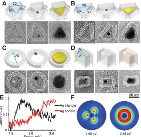
In the equilateral triangular barrel, the cross section of a fully confined Ag NP exhibited an equilateral triangular shape under TEM, with an expected edge length of 25.2 ± 1.9 nm (N = 20) and three rounded corners (Fig. 4A, right; see fig. S56 for large-field-of-view images). The DNA mold remained intact after Ag growth, and wrapped around the Ag NP. No obvious bending or curvature of DNA sidewalls was observed. In the center of the Ag NP, a circular-shape shade with 5 nm diameter was observed and was assigned to the Au seed in the DNA mold. TEM imaging of a tilted conformation further confirmed the 3D nature of the NP (fig. S57A). High-resolution TEM plus electron diffraction characterization (fig. S57, B and C) also revealed the highly crystalline nature of the Ag NP, which was consistent with its smooth surface morphology (absence of grain boundaries) and single seed-mediated growth pathway. In the right triangular barrel with a measured 21.9 ± 1.1 nm by 30.2 ± 0.5 nm by 37.9 ± 0.5 nm cavity (N = 20), the fully grown Ag NP demonstrated a triangular cross section shape with 21.7 ± 0.6 nm by 24.2 ± 0.7 nm by 28.2 ± 0.7 nm dimension (N = 20; Fig. 4B, right; see fig. S58 for large-field-of-view images). Similar to the equilateral triangular NP, the right-triangular NP also exhibited rounded corners. In the circular-shaped channel, a Ag sphere NP was observed with a circular cross section diameter of 25.5 ± 1.6 nm (N = 20; Fig. 4C, right; see fig. S59 for large-field-of-view images; see fig. S60 for images of tilted conformations, an HRTEM image revealing the spherical nature of the cast NP, and the electron diffraction result), consistent with our design. In contrast to the capping ligand method, DNA-based nanocasting enabled one-pot parallel production of distinct prescribed shapes by mixing different molds in a single reaction solution (see three distinct Ag shapes in fig. S65).
In the open barrels, only NPs growing laterally rather than vertically were confined to form specific shapes. This resulted in NP casting yields of 10–18% (Table 1), which is
significantly lower than that of the fully enclosed cavity. Most of the unconfined NPs exhibited spherical shapes, and did not fully occupy the channels (see figs. S55, S56, S58, and S59 for large-field-of-view images). See Table 1 for casting yield and table S6 for yields of different steps in constructing the mold. For each design of open-ended DNA molds, the barrel formation yield (5–10%) (see gel images in figs. S31, S33, and S35), seed decoration yield (60–75%), and the casting yield (10–18%) (table S6) (29) were determined following the same definition described above.
NIH-PA Author Manuscript
NIH-PA Author Manuscript
Experimental characterization and simulation of plasmonic properties
Next we used electron energy loss spectroscopy (EELS) (42) and electromagnetism-based simulations (29) to characterize NP plasmonic behavior, both experimentally andtheoretically, of the equilateral Ag triangle in Fig. 4A and Ag sphere in Fig. 4C.
For the equilateral Ag triangle, EELS measurement (Fig. 4E) showed an intense peak around 2.30 eV (corresponding to 540 nm) with a wide shoulder peak around 3.26 eV
(corresponding to 380 nm). Simulation for the same equilateral Ag triangle (figs. S7 and S8) revealed, in the presence of the DNA mold and carbon film beneath, a strong dipolar mode around 1.95 eV from the plasmonic resonance near the corners (Fig. 4F), various resonance modes between 2.45 eV (corresponding to 506 nm) and 3.70 eV (corresponding to 336 nm) near the center and edges, and a bulk Ag plasmon mode at 3.80 eV (corresponding to 327 nm, fig. S9). The red-shifting of the simulated EELS spectra with respect to experiment may be due to variations in the carbon film thickness of the TEM grid, the dielectric function of the DNA mold, the NP thickness, as well as the radii of the rounded NP corners (figs. S10 and S11) (29). Simulation of optical properties of the NPs in aqueous environment indicated similar plasmonic properties to those in vacuum (figs. S16 to S21) (29), suggesting the potential utility of the NPs for biosensing applications. Comparison with a previously published EELS result for a triangular Ag NP of similar dimensions (43) indicates a relative offset of ~0.1 eV for the predicted NP dipolar mode resonance, which may be due to the distinct substrate (mica) and surface coating employed. In contrast, a larger energy offset of 0.4 eV is observed relative to a previously examined larger Ag triangle of 75 nm dimension (43), indicating the importance of NP size on the resonance energy.
A highly distinct EELS response was measured for the Ag sphere (Fig. 4E), indicating shape-specific plasmonic properties. A single resonance band was observed near 3.26 eV (corresponding to 380 nm) experimentally, which was ascribed to the simulated (fig. S12) dipolar mode near 2.85 eV (corresponding to 435 nm, Fig. 4F) at the edge of the NP. Simulations also suggested several minor resonance modes between the 3.30 eV
(corresponding to 376 nm) and 3.65 eV (corresponding to 340 nm) regions near the center of the NP (fig. S13). Similar environmentally-sensitive resonance was also observed for the cast Ag sphere (figs. S14 and S15).
Further high-resolution EELS characterization or polarized light excitation using dark-field microscopy on the surface immobilized metal NPs should reveal the spatial distribution of excited surface plasmons (43, 44), which could enrich our fundamental understanding of nano-optics.
Casting a Au cuboid
To test the material versatility of our strategy, we cast a Au NP in a DNA barrel containing a 16 nm by 21 nm rectangular open tunnel. Compared to the Ag NP, the growth kinetics of the Au NP in 0.5× TBE/10 mM Mg(NO3)2 buffer was much slower. After 30 min reaction time,
no obvious size increase was observed for the NP, which was ascribed to the chelating effect of EDTA to gold precursors. Removing EDTA from the reaction buffer significantly promoted the growth kinetics, where a reaction time of 30 min generated a Au NP with a
NIH-PA Author Manuscript
NIH-PA Author Manuscript
13.5 ± 0.7 nm by 19.0 ± 1.8 nm (N = 20) rectangular cross section within the barrel (Fig. 4D, right; see fig. S61 for large-field-of-view images). The casting yield (6%, table S6) was determined following the same definition described above. See (29) for yields of each step.
Composite structures
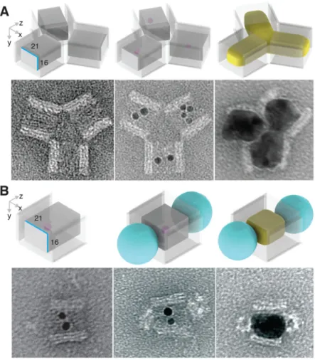
In addition to structural confinement and protection against undesired NP aggregation, the DNA mold provides a uniquely addressable three-dimensional coating for the NP to be cast, which facilitates the composition of the DNA molds into higher order complex structures. Here, we experimentally constructed a Y-shape Ag NP branched structure and a QD-Ag-QD composite structure.
A Y-shape DNA mold was assembled from three DNA barrels carrying complementary connector strands (fig. S37). Each barrel carries ssDNA handles to capture Au seeds. After seed decoration, TEM images revealed formation of the desired trimer (Fig. 5A, center; see fig. S45 for large-field-of-view images), as well as unintended byproducts, such as
incomplete assembled dimers and multimers (e.g., pentamers and hexamers). Ag growth within the Y-shape barrel complex generated individual NP within each barrel, which together formed a Y-shape NP cluster (Fig. 5A, right; see fig. S62 for large-field-of-view images). The measured widths of Ag NP within each barrel were 22.7 ± 1.8 nm, 24.3 ± 1.4 nm, and 25.5 ± 0.9 nm (N = 20), slightly larger than the designed 21 nm width of the barrel mold. At the center of the Y-shape barrel complex, where the growth fronts of the Ag NPs met, narrow (< 2 nm) inter-particle gaps were observed. The casting yield (10%, table S6) was determined following the same definition described above. See (29) for yields of each step.
To build a composite structure where a Ag NP was sandwiched between two QDs, 5 or 6 biotin groups were introduced at both ends of a DNA barrel with a 21-16-30 nm cuboid tunnel (see fig. S38 for design details). After attaching Au seed inside the barrel, streptavidin coated QDs were introduced and bound to both ends of the barrel. TEM imaging revealed the formation of the designed sandwiched structure between QDs and the seed-decorated barrels (Fig. 5B, middle; see fig. S46 for large-field-of-view images). After staining with uranium salt (29), the white sphere with 16–21 nm diameter at the ends of the barrel was attributed to the PEG and streptavidin coating layer around QD cores (CdSe@ZnS; see fig. S64 for control experiments with QD only). 88% seed-decorated barrels (table S6) were conjugated with QDs at both ends (N = 129). Note that no QDs were found attached to side surfaces of DNA barrels, confirming that QD attachment was specifically mediated by biotins as designed. After Ag growth, TEM imaging revealed the formation of QD-Ag-QD composite structures (31% casting yield in table S6 and Fig. 5B, right) [see fig. S63 for large-field-of-view images and (29) for yields of each step]. Ag NPs exhibited a 20.5 ± 0.5 nm by 28.4 ± 1.3 nm projection (N = 20), consistent with the designed size of DNA barrel mold. Thus, we demonstrated the assembly of QD at prescribed locations on selected faces of a nonspherical metal NP.
NIH-PA Author Manuscript
NIH-PA Author Manuscript
Optimization of the casting process
The stoichiometry between anti-handle and Au seed was set to 1:1 to minimize the
undesirable effect of surface-immobilized ssDNA on NP growth. To increase the formation yield of box-like DNA molds, the number of connectors on the barrels was optimized. Increasing the connectors from six to fourteen at each end of the barrel increased the yield from less than 10% to 31%; whereas changing the lid-to-barrel ratio from 2:1 to 6:1 only slightly raised the yield from 28% to 33%.
The effectiveness of the stiffness-based design strategy is verified by the following failed mold designs: single-layered DNA mold did not produce pre-designed cross section shapes (see fig. S67 for TEM images and table S4 for simulations); when the number of crossovers decreased to one or two, such as in the cases of DNA triangles that displayed less than 16 nm sidewalls, destructed DNA molds were observed during metal growth (see figs. S69 and S71 for examples). We also note that although chemical inhibition between phosphate groups and the growing NP is also expected to occur (45, 46), it was not optimized as a design parameter for programming the shape in the current study. Additionally, structural integrity of DNA molds was affected by the buffer ionic condition. At 10 mM magnesium nitrate concentration, DNA mold remained intact for 1 day at 1–2 mM reactant
concentration, but deteriorated when the reactant concentration was higher than 20 mM. For more detailed discussions on the optimization of nanocasting, and various sub-optimal or failed DNA molds used in the optimization experiments, see (29) and figs. S66 to S75.
Discussion
Previous work on casting NPs at a scale below 25 nm only had limited success, largely because of the lack of shape-programmable molds with both mechanical rigidity and surface programmability to enable site-specific seed decoration followed by constrained growth. High-stiffness nanomolds such as viral capsids (35) and porous inorganic materials (47) are difficult to program into arbitrary geometric shapes, limiting their utility for nanoscale casting of diverse NP geometries and dimensions. Previous reports have shown the programming of 2D inorganic shapes with DNA templates. For example, the growth of metals mediated by randomly-distributed nanocluster seeds (48–52) or strategically-positioned NP seeds (53, 54) on a DNA nanostructure surface has produced diverse 2D shapes. However, rough surface morphologies (55), and inhomogeneous width distributions along the DNA skeletons (56) are often observed for these unconfined metalized products. Our work differs by providing a general way to construct inorganic nanostructures with arbitrarily user-specified 3D shapes and precise prescribed dimensions, by using DNA nanostructures to spatially confine the growth of the final shape (rather than seeding the initial shape) of the inorganic NP. Importantly, the cast NP retains the addressable coating. To fabricate such surface modified NPs, traditional chemical synthesis typically involves multiple-step low-yield conjugation and purification after NP formation.
Rapid progress in DNA self-assembly will help to further expand the complexity and diversity of the NP shapes. Recent advances in scaffold-free, 3D construction with DNA
NIH-PA Author Manuscript
NIH-PA Author Manuscript
bricks has already demonstrated highly complex cavities (e.g., toroidal shape cavity) and tunnels (e.g., crossed and branched tunnels) encoded in sub-25 nm DNA cuboids (26). It is conceivable that such complex cavity and tunnel shapes may be transferred to inorganic substrates via DNA nanocasting. Further, because of the length limitation of the M13 viral scaffold strand, current mutli-layered mold designs using scaffolded DNA origami are restricted to produce sub-25 nm cavities. However, by using scaffold-free construction with DNA bricks (25, 26), DNA origami made from longer scaffolds (57), or hierarchical assembly of multiple origami (28, 58) and brick structures, nanomolds with much larger and more complex cavities may be achieved. In addition to increasing the shape complexity of the cast NPs, further research will also focus on expanding the material diversity of the NPs. Aside from Ag and Au, the Au seed can also mediate the growth of other diverse inorganic materials [e.g., metals (38, 39), oxides (40) and complex salt (41)] at mild conditions, for potential casting with DNA molds. Replacing Au seed with metal bind peptides may further expand the cast diversity (e.g., metals, metal oxides, and chalco-genides) (59).
The casting yield (step 4) may be further optimized by using computer-aided design of DNA molds with high mechanical integrity to minimize mold distortion during growth. The formation of 3D enclosed, seed-decorated mold may be improved by optimizing self-assembly conditions [e.g., using isothermal folding (60)] or exploring alternative construction strategies [e.g., using DNA bricks (26)]. Additionally, replacing Au seeds (which tend to aggregate at DNA origami mold folding conditions) with more stable metal-binding peptides could simplify the current multi-step assembly strategy and enable one-step, high-yield formation of DNA molds with enclosed peptide seeds.
The shape- and surface-controlled inorganic NPs fabricated herein may eventually enable novel applications in diverse fields ranging from biosensing, to photonics, and to
nanoelectronics. Near term applications are likely those based on single-particle properties. For example, DNA nanocasting produces a prescribed metal shape with a uniquely
addressable coating, which may display the binding site for target molecule at the near-field maximum position and hence enable highly sensitive detection. Because optical simulations of the cast NPs in water suggest geometry-specific dipolar resonances and near-field distributions (29), highly multiplexed sensing may be achieved using diverse programmed metal shapes.
DNA-based nanoscasting represents a general approach for synthesizing inorganic nano-structures with arbitrarily prescribed 3D shapes (29). Together with other strategies for transferring the geometric information of DNA nanostructures to diverse inorganic materials [e.g., coating DNA nanostructures with inorganic oxides (61) or etching graphene using metalized DNA nanostrucures as lithography masks (52)], it points to a new kind of manufacture framework: DNA-directed, digitally programmable fabrication of inorganic nanostructures and devices. Such DNA-based inorganic nano-fabrication may eventually enable future production of sophisticated devices such as nanoscale optical circuits, electronic computers, and perhaps even inorganic molecular robots, each with their blueprints (or “genomes”) encoded in the DNA molecules that constitute their “nano-fabricators”.
NIH-PA Author Manuscript
NIH-PA Author Manuscript
Materials and methods
DNA mold design
caDNAno (30) was used to design the sequences and routing of staple strands using the scaffold strand (mutated P8064) derived from M13 bacteriophage.
Simulation of DNA mold mechanical properties
The mechanical properties of DNA molds were predicted using the finite element method based on the ground-state 3D solution structure predicted by CanDo and standard geometric and mechanical properties of B-form DNA (31, 32). Mechanical deformations of the molds were computed in response to internal point- and distributed-loading using the commercial finite element software ADINA (ADINA RD, Inc., Watertown, MA). Normal Mode Analysis was performed to compute the lowest energy modes of deformation of the molds (29, 62, 63).
DNA mold folding
Assembly of DNA-origami molds was accomplished following previous reported protocol (22, 23). In a one-pot reaction, 50 nM scaffold was mixed with 250 nM of every staple strands (Bioneer Inc. or IDTDNA Inc.) in a buffer including 5 mM Tris, 1 mM EDTA, 16 mM MgCl2, (pH 8) and subjected to a thermal-annealing ramp that cooled from 80°C to
65°C over 75 min and then cooled from 64°C to 24°C over 70 hours.
Gel purification
40 μL of folding products were mixed with 10 μL of glycerol, and loaded into 1.5% agarose gel pre-stained with Sybr Safe containing 0.5× TBE and 10 mM Mg(NO3)2. The
electrophoresis was running at 75 V for three hours in a gel box incubated in an ice-water bath. Monomer band was excised and origami was recovered by pestle crushing, followed by centrifugation for 3 min at 6000 rpm at room temperature using “Freeze ’N Squeeze” DNA Gel Extraction spin columns (Bio-Rad). Recovered DNA molds were stored at 4°C for further use.
DNA-decoration onto 5-nm Au seeds
Conjugation of thiolated DNA onto 5-nm Au seeds was achieved following previous reported protocol (64). In a typical experiment, 20 μL 2.5 μM phosphine-coated 5-nm Au seed was mixed with 0.5 μL 2 M NaNO3 and 0.65 μL 100 μM thiolated DNA in 0.25× TBE
buffer. The reaction solution was incubated at room temperature for 36 hours in dark. After that, the reaction solution was loaded into 1% agarose gel containing 0.5× TBE buffer. The electrophoresis was running at 95 V for 1 hour in a gel box on an ice-water bath. The purple band was recovered by pestle crushing, followed by centrifugation for 3 min at 10,000 rpm at room temperature using “Freeze ’N Squeeze” DNA Gel Extraction spin columns (Bio-Rad). Recovered DNA molds were stored at 4°C in dark for further use. The sequence for the thiolated DNA was: TATGAGAAGTTAGGAATGTTATTTTT-Thiol. Note that thiol group was modified at the 3′ end of anti-handle sequence
TATGAGAAGTTAGGAATGTTA via a TTTTT spacer.
NIH-PA Author Manuscript
NIH-PA Author Manuscript
Seed decoration of DNA mold
Purified DNA molds were mixed with 50 mM NaNO3 and 10 nM purified 5-nm Au-DNA
conjugates(at a seed-to-barrel stoichiometry ratio of 2:1), and incubating at 35°C for 16 hours, followed by slowly annealing to 24°C over 3 hours. The reaction buffer was then purified using S300 spin column (GE healthcare) by centrifugation for 2 min at 750 g at room temperature to remove excessive Au-DNA conjugates.
Lid attachment onto DNA mold
DNA lids were mixed with the seed-decorated DNA barrels (at lid-to-barrel stoichiometry ratio of 3:1) at 35°C for 16 hours, and annealed to 24°C over 3 hours.
Metal growth
For Ag growth, to 5 μL purified seed-decorated DNA molds, 0.5 μL 14 mM AgNO3 and 0.5
μL 20 mM ascorbic acid were added at room temperature, and pipetted for 30 times for mixing. Then the reaction solution was kept in dark at room temperature for 4 min to 20 min. For Au growth, 0.5 μL 14 mM HAuCl4 and 0.5 μL 20 mM ascorbic acid were added to
5-μL purified seed-decorated DNA molds in 0.5× TB buffer at room temperature, and pipetted for 30 times for mixing. Then the reaction solution was kept in dark at room temperature from 20 min to 2 hours.
TEM
3.5 μL NPs were adsorbed onto glow discharged carbon-coated TEM grids for 2 min and then wiped away, followed by staining using 3.5 μL 2% aqueous uranyl formate solution containing 25 mM NaOH for 45 s. Imaging was performed using an JEOL 1400 operated at 80 keV. High-resolution TEM and electron diffraction were acquired using a JEOL 2010 with FEG operated at 200 keV for unstained NP sample deposited onto amorphous carbon film.
Yield analysis
Seed decoration yield from step 2, box closure yield from step 3, and casting yield from step 4 (29) in Fig. 1A were acquired through direct counting of NP with prescribed shapes and dimensions from each of the three projection views. For each individual barrel and lid, the barrel and the lid formation yield from step 1a (Fig. 1A) were determined from agarose gel (29).
EELS experimental characterization
The low loss EELS data were collected with TEAM I at the Lawrence Berkeley National Lab, a Monochromated TEM operated at 80 keV. The EELS data were collected in the TEM mode under vacuum for the unstained NP sample deposited onto amorphous carbon film.
Simulation of NP plasmonic and optical properties
EELS results were simulated using MNPBEM (65, 66) that is freely available as a MATLAB (The MathWorks, Inc., Natick, MA) toolbox (29). Optical property simulations were performed using the commercial finite element software COMSOL (COMSOL Inc.,
NIH-PA Author Manuscript
NIH-PA Author Manuscript
Burlington, MA) employing the full 3D continuum electromagnetic Helmholtz equation (29, 67, 68).
Supplementary Material
Refer to Web version on PubMed Central for supplementary material.
Acknowledgments
The authors thank Y. Ke, J. Shen, and B. Wei for discussion, and E. Haney, D. Pastuszak and E. Chen for assistance in draft preparation. This work is supported by a DARPA Young Faculty Award (N660011114136), an Office of Naval Research (ONR) Young Investigator Program Award (N000141110914), ONR grants
(N000141010827, N000141310593, and N000141410610), an Army Research Office grant (W911NF1210238), a National Institutes of Health (NIH) Director’s New Innovator Award (1DP2OD007292), a National Science Foundation (NSF) Faculty Early Career Development Award (CCF1054898), an NSF Expedition in Computing Award (CCF1317291), NSF grants (CCF1162459, CMMI1333215, CMMI1334109, and CMMI1344915) and Wyss Institute funds to P.Y., and ONR grants (DURIP N000141310664 and N000141210621) and NSF-DMREF grant (CMMI1334109) to M.B., E.B., and Y.H. E.B. additionally acknowledges NSERC for funding. This work was performed in part at the Center for Nanoscale Systems (CNS), a member of the National Nanotechnology Infrastructure Network (NNIN), which is supported by the National Science Foundation under NSF award no. ECS-0335765. CNS is part of Harvard University. The EELS of the silver NPs was measured at NCEM, which is supported by the Office of Science, Office of Basic Energy Sciences of the U.S. Department of Energy under Contract No. DE-AC0205CH11231. W.S. designed the system, conducted the experiments, and analyzed the data E.B. designed and performed optical and EELS simulation, and analyzed the data. Y.H. designed and performed mechanical simulation, and analyzed the data. W.L.W. performed EELS experiments and analyzed the data. A.G. performed experiments and analyzed the data. M.B. designed and supervised the simulation study and interpreted the data. P.Y. conceived, designed, and supervised the study and interpreted the data. All authors wrote the manuscript. All data described in this Article are presented in the supplementary materials.
References and Notes
1. Pompa PP, Martiradonna L, Torre AD, Sala FD, Manna L, De Vittorio M, Calabi F, Cingolani R, Rinaldi R. Metal-enhanced fluorescence of colloidal nanocrystals with nanoscale control. Nat Nanotechnol. 2006; 1:126–130.10.1038/nnano.2006.93 [PubMed: 18654164]
2. Wang F, Li C, Chen H, Jiang R, Sun LD, Li Q, Wang J, Yu JC, Yan CH. Plasmonic harvesting of light energy for Suzuki coupling reactions. J Am Chem Soc. 2013; 135:5588–5601.10.1021/ ja310501y [PubMed: 23521598]
3. Kildishev AV, Boltasseva A, Shalaev VM. Planar photonics with metasurfaces. Science. 2013; 339:1232009.10.1126/science.1232009 [PubMed: 23493714]
4. Koh AL, Fernández-Domínguez AI, McComb DW, Maier SA, Yang JKW. High-resolution mapping of electron-beam-excited plasmon modes in lithographically defined gold nanostructures. Nano Lett. 2011; 11:1323–1330.10.1021/nl104410t [PubMed: 21344928]
5. Sun Y, Xia Y. Shape-controlled synthesis of gold and silver nanoparticles. Science. 2002; 298:2176–2179.10.1126/science.1077229 [PubMed: 12481134]
6. Xia Y, Xiong Y, Lim B, Skrabalak SE. Shape-controlled synthesis of metal nanocrystals: Simple chemistry meets complex physics? Angew Chem Int Ed. 2009; 48:60–103.10.1002/anie.200802248 7. Ming T, Feng W, Tang Q, Wang F, Sun L, Wang J, Yan C. Growth of tetrahexahedral gold
nanocrystals with high-index facets. J Am Chem Soc. 2009; 131:16350–16351.10.1021/ja907549n [PubMed: 19856912]
8. Ma N, Sargent EH, Kelley SO. One-step DNA-programmed growth of luminescent and biofunctionalized nanocrystals. Nat Nanotechnol. 2009; 4:121–125.10.1038/nnano.2008.373 [PubMed: 19197315]
9. Lohse SE, Murphy CJ. Applications of colloidal inorganic nanoparticles: From medicine to energy. J Am Chem Soc. 2012; 134:15607–15620.10.1021/ja307589n [PubMed: 22934680]
10. Wang Z, Tang L, Tan LH, Li J, Lu Y. Discovery of the DNA “genetic code” for abiological gold nanoparticle morphologies. Angew Chem Int Ed. 2012; 51:9078–9082.10.1002/anie.201203716
NIH-PA Author Manuscript
NIH-PA Author Manuscript
11. Ruan L, Ramezani-Dakhel H, Chiu CY, Zhu E, Li Y, Heinz H, Huang Y. Tailoring molecular specificity toward a crystal facet: A lesson from biorecognition toward Pt111. Nano Lett. 2013; 13:840–846.10.1021/nl400022g [PubMed: 23320831]
12. Puzder A, Williamson AJ, Zaitseva N, Galli G, Manna L, Alivisatos AP. The effect of organic ligand binding on the growth of CdSe nanoparticles probed by ab initio calculations. Nano Lett. 2004; 4:2361–2365.10.1021/nl0485861
13. Yu J, Becker ML, Carri GA. A molecular dynamics simulation of the stability-limited growth mechanism of peptide-mediated gold-nanoparticle synthesis. Small. 2010; 6:2242–2245.10.1002/ smll.201000889 [PubMed: 20853372]
14. Bealing CR, Baumgardner WJ, Choi JJ, Hanrath T, Hennig RG. Predicting nanocrystal shape through consideration of surface-ligand interactions. ACS Nano. 2012; 6:2118–2127.10.1021/ nn3000466 [PubMed: 22329695]
15. Seeman NC. DNA in a material world. Nature. 2003; 421:427–431.10.1038/nature01406 [PubMed: 12540916]
16. Chen JH, Seeman NC. Synthesis from DNA of a molecule with the connectivity of a cube. Nature. 1991; 350:631–633.10.1038/350631a0 [PubMed: 2017259]
17. Winfree E, Liu F, Wenzler LA, Seeman NC. Design and self-assembly of two-dimensional DNA crystals. Nature. 1998; 394:539–544.10.1038/28998 [PubMed: 9707114]
18. Shih WM, Quispe JD, Joyce GF. A 1.7-kilobase single-stranded DNA that folds into a nanoscale octahedron. Nature. 2004; 427:618–621.10.1038/nature02307 [PubMed: 14961116]
19. Rothemund PWK. Folding DNA to create nanoscale shapes and patterns. Nature. 2006; 440:297– 302.10.1038/nature04586 [PubMed: 16541064]
20. Yin P, Hariadi RF, Sahu S, Choi HM, Park SH, Labean TH, Reif JH. Programming DNA tube circumferences. Science. 2008; 321:824–826.10.1126/science.1157312 [PubMed: 18687961] 21. He Y, Ye T, Su M, Zhang C, Ribbe AE, Jiang W, Mao C. Hierarchical self-assembly of DNA into
symmetric supramolecular polyhedra. Nature. 2008; 452:198–201.10.1038/nature06597 [PubMed: 18337818]
22. Douglas SM, Dietz H, Liedl T, Högberg B, Graf F, Shih WM. Self-assembly of DNA into nanoscale three-dimensional shapes. Nature. 2009; 459:414–418.10.1038/nature08016 [PubMed: 19458720]
23. Dietz H, Douglas SM, Shih WM. Folding DNA into twisted and curved nanoscale shapes. Science. 2009; 325:725–730.10.1126/science.1174251 [PubMed: 19661424]
24. Han D, Pal S, Nangreave J, Deng Z, Liu Y, Yan H. DNA origami with complex curvatures in three-dimensional space. Science. 2011; 332:342–346.10.1126/science.1202998 [PubMed: 21493857]
25. Wei B, Dai M, Yin P. Complex shapes self-assembled from single-stranded DNA tiles. Nature. 2012; 485:623–626.10.1038/nature11075 [PubMed: 22660323]
26. Ke Y, Ong LL, Shih WM, Yin P. Three-dimensional structures self-assembled from DNA bricks. Science. 2012; 338:1177–1183.10.1126/science.1227268 [PubMed: 23197527]
27. Han D, Pal S, Yang Y, Jiang S, Nangreave J, Liu Y, Yan H. DNA gridiron nanostructures based on four-arm junctions. Science. 2013; 339:1412–1415.10.1126/science.1232252 [PubMed:
23520107]
28. Iinuma R, Ke Y, Jungmann R, Schlichthaerle T, Woehrstein JB, Yin P. Polyhedra self-assembled from DNA tripods and characterized with 3D DNA-PAINT. Science. 2014; 344:65–69.10.1126/ science.1250944 [PubMed: 24625926]
29. See supplementary materials on Science Online.
30. Douglas SM, Marblestone AH, Teerapittayanon S, Vazquez A, Church GM, Shih WM. Rapid prototyping of three-dimensional DNA-origami shapes with caDNAno. Nucleic Acids Res. 2009; 37:5001–5006.10.1093/nar/gkp436 [PubMed: 19531737]
31. Castro CE, Kilchherr F, Kim DN, Shiao EL, Wauer T, Wortmann P, Bathe M, Dietz H. A primer to scaffolded DNA origami. Nat Methods. 2011; 8:221–229.10.1038/nmeth.1570 [PubMed: 21358626]
NIH-PA Author Manuscript
NIH-PA Author Manuscript
32. Kim DN, Kilchherr F, Dietz H, Bathe M. Quantitative prediction of 3D solution shape and flexibility of nucleic acid nanostructures. Nucleic Acids Res. 2012; 40:2862–2868.10.1093/nar/ gkr1173 [PubMed: 22156372]
33. Ke Y, Douglas SM, Liu M, Sharma J, Cheng A, Leung A, Liu Y, Shih WM, Yan H. Multilayer DNA origami packed on a square lattice. J Am Chem Soc. 2009; 131:15903–15908.10.1021/ ja906381y [PubMed: 19807088]
34. Michel JP, Ivanovska IL, Gibbons MM, Klug WS, Knobler CM, Wuite GJ, Schmidt CF.
Nanoindentation studies of full and empty viral capsids and the effects of capsid protein mutations on elasticity and strength. Proc Natl Acad Sci USA. 2006; 103:6184–6189.10.1073/pnas.
0601744103 [PubMed: 16606825]
35. Dickerson MB, Sandhage KH, Naik RR. Protein- and peptide-directed syntheses of inorganic materials. Chem Rev. 2008; 108:4935–4978.10.1021/cr8002328 [PubMed: 18973389]
36. Zhao Z, Jacovetty EL, Liu Y, Yan H. Encapsulation of gold nanoparticles in a DNA origami cage. Angew Chem Int Ed. 2011; 50:2041–2044.10.1002/anie.201006818
37. Zanchet D, Micheel CM, Parak WJ, Gerion D, Alivisatos AP. Electrophoretic isolation of discrete Au nanocrystal/DNA conjugates. Nano Lett. 2001; 1:32–35.10.1021/nl005508e
38. Fan FR, Liu DY, Wu YF, Duan S, Xie ZX, Jiang ZY, Tian ZQ. Epitaxial growth of heterogeneous metal nanocrystals: From gold nano-octahedra to palladium and silver nanocubes. J Am Chem Soc. 2008; 130:6949–6951.10.1021/ja801566d [PubMed: 18465860]
39. Wang F, Li C, Sun LD, Wu H, Ming T, Wang J, Yu JC, Yan CH. Heteroepitaxial growth of high-index-faceted palladium nanoshells and their catalytic performance. J Am Chem Soc. 2011; 133:1106–1111.10.1021/ja1095733 [PubMed: 21174411]
40. Ghosh Chaudhuri R, Paria S. Core/shell nanoparticles: Classes, properties, synthesis mechanisms, characterization, and applications. Chem Rev. 2012; 112:2373–2433.10.1021/cr100449n [PubMed: 22204603]
41. Maurin-Pasturel G, Long J, Guari Y, Godiard F, Willinger MG, Guerin C, Larionova J. Nanosized heterostructures of Au@Prussian blue analogues: Towards multifunctionality at the nanoscale. Angew Chem Int Ed. 2014; 53:3872–3876.10.1002/anie.201310443
42. Scholl JA, Koh AL, Dionne JA. Quantum plasmon resonances of individual metallic nanoparticles. Nature. 2012; 483:421–427.10.1038/nature10904 [PubMed: 22437611]
43. Nelayah J, Kociak M, Stéphan O, García de Abajo FJ, Tencé M, Henrard L, Taverna D, Pastoriza-Santos I, Liz-Marzán LM, Colliex C. Mapping surface plasmons on a single metallic nanoparticle. Nat Phys. 2007; 3:348–353.10.1038/nphys575
44. Myroshnychenko V, Nelayah J, Adamo G, Geuquet N, Rodríguez-Fernández J, Pastoriza-Santos I, MacDonald KF, Henrard L, Liz-Marzán LM, Zheludev NI, Kociak M, García de Abajo FJ. Plasmon spectroscopy and imaging of individual gold nanodecahedra: A combined optical microscopy, cathodoluminescence and electron energy-loss spectroscopy study. Nano Lett. 2012; 12:4172–4180.10.1021/nl301742h [PubMed: 22746278]
45. Berti L, Burley GA. Nucleic acid and nucleotide-mediated synthesis of inorganic nanoparticles. Nat Nanotechnol. 2008; 3:81–87.10.1038/nnano.2007.460 [PubMed: 18654466]
46. Tan SJ, Campolongo MJ, Luo D, Cheng W. Building plasmonic nanostructures with DNA. Nat Nanotechnol. 2011; 6:268–276.10.1038/nnano.2011.49 [PubMed: 21499251]
47. Gao C, Zhang Q, Lu Z, Yin Y. Templated synthesis of metal nanorods in silica nanotubes. J Am Chem Soc. 2011; 133:19706–19709.10.1021/ja209647d [PubMed: 22085084]
48. Braun E, Eichen Y, Sivan U, Ben-Yoseph G. DNA-templated assembly and electrode attachment of a conducting silver wire. Nature. 1998; 391:775–778.10.1038/35826 [PubMed: 9486645] 49. Yan H, Park SH, Finkelstein G, Reif JH, LaBean TH. DNA-templated self-assembly of protein
arrays and highly conductive nanowires. Science. 2003; 301:1882–1884.10.1126/science.1089389 [PubMed: 14512621]
50. Liu J, Geng Y, Pound E, Gyawali S, Ashton JR, Hickey J, Woolley AT, Harb JN. Metallization of branched DNA origami for nanoelectronic circuit fabrication. ACS Nano. 2011; 5:2240–
2247.10.1021/nn1035075 [PubMed: 21323323]
NIH-PA Author Manuscript
NIH-PA Author Manuscript
51. Schreiber R, Kempter S, Holler S, Schüller V, Schiffels D, Simmel SS, Nickels PC, Liedl T. DNA origami-templated growth of arbitrarily shaped metal nanoparticles. Small. 2011; 7:1795– 1799.10.1002/smll.201100465 [PubMed: 21608127]
52. Jin Z, Sun W, Ke Y, Shih CJ, Paulus GL, Hua Wang Q, Mu B, Yin P, Strano MS. Metallized DNA nanolithography for encoding and transferring spatial information for graphene patterning. Nat Commun. 2013; 4:1663.10.1038/ncomms2690 [PubMed: 23575667]
53. Pilo-Pais M, Goldberg S, Samano E, Labean TH, Finkelstein G. Connecting the nanodots: Programmable nanofabrication of fused metal shapes on DNA templates. Nano Lett. 2011; 11:3489–3492.10.1021/nl202066c [PubMed: 21732612]
54. Kuzyk A, Schreiber R, Fan Z, Pardatscher G, Roller EM, Högele A, Simmel FC, Govorov AO, Liedl T. DNA-based self-assembly of chiral plasmonic nanostructures with tailored optical response. Nature. 2012; 483:311–314.10.1038/nature10889 [PubMed: 22422265]
55. Samano EC, Pilo-Pais M, Goldberg S, Vogen BN, Finkelstein G, LaBean TH. Self-assembling DNA templates for programmed artificial biomineralization. Soft Matter. 2011; 7:3240– 3245.10.1039/c0sm01318h
56. Fischler M, Simon U, Nir H, Eichen Y, Burley GA, Gierlich J, Gramlich PM, Carell T. Formation of bimetallic Ag-Au nanowires by metallization of artificial DNA duplexes. Small. 2007; 3:1049– 1055.10.1002/smll.200600534 [PubMed: 17309092]
57. Zhang H, Chao J, Pan D, Liu H, Huang Q, Fan C. Folding super-sized DNA origami with scaffold strands from long-range PCR. Chem Commun. 2012; 48:6405–6407.10.1039/c2cc32204h 58. Woo S, Rothemund PWK. Programmable molecular recognition based on the geometry of DNA
nanostructures. Nat Chem. 2011; 3:620–627.10.1038/nchem.1070 [PubMed: 21778982] 59. Sarikaya M, Tamerler C, Jen AKY, Schulten K, Baneyx F. Molecular biomimetics:
Nanotechnology through biology. Nat Mater. 2003; 2:577–585.10.1038/nmat964 [PubMed: 12951599]
60. Sobczak J-PJ, Martin TG, Gerling T, Dietz H. Rapid folding of DNA into nanoscale shapes at constant temperature. Science. 2012; 338:1458–1461.10.1126/science.1229919 [PubMed: 23239734]
61. Surwade SP, Zhou F, Wei B, Sun W, Powell A, O’Donnell C, Yin P, Liu H. Nanoscale growth and patterning of inorganic oxides using DNA nanostructure templates. J Am Chem Soc. 2013; 135:6778–6781.10.1021/ja401785h [PubMed: 23574340]
62. Bathe M. A finite element framework for computation of protein normal modes and mechanical response. Proteins. 2008; 70:1595–1609.10.1002/prot.21708 [PubMed: 17975833]
63. Brooks B, Janežič D, Karplus M. Harmonic analysis of large systems. I. methodology. J Comput Chem. 1995; 16:1522–1542.10.1002/jcc.540161209
64. Sharma J, Chhabra R, Andersen CS, Gothelf KV, Yan H, Liu Y. Toward reliable gold nanoparticle patterning on self-assembled DNA nanoscaffold. J Am Chem Soc. 2008; 130:7820–7821.10.1021/ ja802853r [PubMed: 18510317]
65. Hohenester U, Trügler A. MNPBEM a matlab toolbox for the simulation of plasmonic nanoparticles. Comput Phys Commun. 2012; 183:370–381.10.1016/j.cpc.2011.09.009
66. Hohenester U. Simulating electron energy loss spectroscopy with the MNPBEM toolbox. Comput Phys Commun. 2014; 185:1177–1187.10.1016/j.cpc.2013.12.010
67. Boulais E, Lachaine R, Meunier M. Plasma mediated off-resonance plasmonic enhanced ultrafast laser-induced nanocavitation. Nano Lett. 2012; 12:4763–4769.10.1021/nl302200w [PubMed: 22845691]
68. Boulais E, Lachaine R, Meunier M. Plasma-mediated nanocavitation and photothermal effects in ultrafast laser irradiation of gold nanorods in water. J Phys Chem C. 2013; 117:9386–
9396.10.1021/jp312475h
69. Desgranges C, Delhommelle J. Molecular dynamics simulation of the nucleation and growth of gold nanoparticles. J Phys Chem C. 2009; 113:3607–3611.10.1021/jp8101546
70. Mariscal M, Velázquez-Salazar J, Yacaman M. Growth mechanism of nanoparticles: Theoretical calculations and experimental results. Cryst Eng Comm. 2012; 14:544–549.10.1039/c1ce05602f
NIH-PA Author Manuscript
NIH-PA Author Manuscript
71. Chuntonov L, Haran G. Maximal Raman optical activity in hybrid single molecule-plasmonic nanostructures with multiple dipolar resonances. Nano Lett. 2013; 13:1285–1290.10.1021/ nl400046z [PubMed: 23384316]
72. Liang H, Rossouw D, Zhao H, Cushing SK, Shi H, Korinek A, Xu H, Rosei F, Wang W, Wu N, Botton GA, Ma D. Asymmetric silver “nanocarrot” structures: Solution synthesis and their asymmetric plasmonic resonances. J Am Chem Soc. 2013; 135:9616–9619.10.1021/ja404345s [PubMed: 23758332]
73. Miller OD, Hsu CW, Reid MT, Qiu W, DeLacy BG, Joannopoulos JD, Soljačić M, Johnson SG. Fundamental limits to extinction by metallic nanoparticles. Phys Rev Lett. 2014;
112:123903.10.1103/PhysRevLett.112.123903 [PubMed: 24724651]
74. Thacker VV, Herrmann LO, Sigle DO, Zhang T, Liedl T, Baumberg JJ, Keyser UF. DNA origami based assembly of gold nanoparticle dimers for surface-enhanced Raman scattering. Nat Commun. 2014; 5:3448.10.1038/ncomms4448 [PubMed: 24622339]
75. Palik, ED. Handbook of Optical Constants of Solids III. Academic Press; New York: 1998. 76. Mie G. Beiträge zur Optik trüber Medien, speziell kolloidaler Metallösungen. Ann Physik. 1908;
330:377–445.10.1002/andp.19083300302
77. Yurkin MA, Hoekstra AG. The discrete dipole approximation: An overview and recent developments. J Quant Spectrosc Radiat Transf. 2007; 106:558–589.
78. Jackson, JD. Classical Electrodynamics. Wiley; New York: 1999.
79. Johnson PB, Christy RW. Optical constants of the noble metals. Phys Rev B. 1972; 6:4370– 4379.10.1103/PhysRevB.6.4370
80. Stockman MI. Nanoplasmonics: Past, present and glimpse into future. Opt Express. 2011; 19:22029–22106.10.1364/OE.19.022029 [PubMed: 22109053]
81. Wiley BJ, Im SH, Li ZY, McLellan J, Siekkinen A, Xia Y. Maneuvering the surface plasmon resonance of silver nanostructures through shape-controlled synthesis. J Phys Chem B. 2006; 110:15666–15675.10.1021/jp0608628 [PubMed: 16898709]
82. Lim DK, Jeon KS, Hwang JH, Kim H, Kwon S, Suh YD, Nam JM. Highly uniform and reproducible surface-enhanced Raman scattering from DNA-tailorable nanoparticles with 1-nm interior gap. Nat Nanotechnol. 2011; 6:452–460.10.1038/nnano.2011.79 [PubMed: 21623360] 83. Lee JH, Kim GH, Nam JM. Directional synthesis and assembly of bimetallic nanosnowmen with
DNA. J Am Chem Soc. 2012; 134:5456–5459.10.1021/ja2121525 [PubMed: 22394110]
84. Church GM, Gao Y, Kosuri S. Next-generation digital information storage in DNA. Science. 2012; 337:1628–1628.10.1126/science.1226355 [PubMed: 22903519]
NIH-PA Author Manuscript
NIH-PA Author Manuscript
Fig. 1. Casting metal NPs with prescribed shapes using DNA nanostructure molds
(A) Design schematic for casting a Ag cuboid. Cyan and green dots denote
(anti-)connectors. (B) Silver (yellow color) and gold (orange color) NPs cast within DNA molds (transparent layer). Ag, silver; Au, gold; QD, quantum dot (depicted as a cyan ball).
NIH-PA Author Manuscript
NIH-PA Author Manuscript
Fig. 2. Mechanical simulations of the rectangular DNA mold
(A) Ground-state solution conformation predicted for DNA mold with a 21 nm by 16 nm by 30 nm cuboid cavity. (B and C) Under point-contact loading (B) and distributed-contact loading (C), the force-deformation F-δ response in x and y directions for the DNA mold in (A). k is the simulated stiffness value along the specific direction.
NIH-PA Author Manuscript
NIH-PA Author Manuscript
Fig. 3. Casting Ag cuboids with prescribed dimensions
(A) A large view TEM image for the Ag NP grown within the DNA mold with a 21 by 16 by 30 nm (or 21-16-30 nm) cuboid cavity [as shown in (B)]. (B to D) Design (top row) and TEM images (rows 2–4) of the Ag NPs grown in the DNA molds with dimensions of 21-16-30 nm (B), 21-16-20 nm (C), and 16-16-20 nm (D). In row 1 of each panel, a small purple dot represents a Au seed. Cast Ag NP is shown in yellow. In rows 2–4 of each panel, a projection model is presented to the left of the TEM images. The TEM images shows from left to right: the empty DNA box, the DNA box decorated with the Au seed (small dark dots; see figs. S47 to S49 for large-field-of-view images), the DNA box containing the fully grown Ag NP (dark rectangles with rounded corners; see figs. S52 to S54 for large-field-of-view images).
NIH-PA Author Manuscript
NIH-PA Author Manuscript
Fig. 4. Casting Ag and Au NPs with prescribed cross section shapes
In (A) to (D), the top row shows the design and the bottom row shows the TEM images of the empty barrel (left), the seed-decorated barrel (middle), and the fully grown NP (right). In the top row of each panel, a small purple dot represents a Au seed. Cast Ag NP is shown in yellow and Au NP is shown in orange. (A) A Ag NP with a 25 nm equilateral triangular cross section. See figs. S32, S42, and S56 for large-field-of-view images. (B) A Ag NP with a 22 nm – 24 nm – 28 nm right-angled triangular cross section. See figs. S34, S43, and S58 for large-field-of-view images. (C) A Ag NP with a 25 nm circular shape cross section. See figs. S36, S44, and S59 for large-field-of-view images. (D) A Au NP with 19 nm by 14 nm rectangle cross section. See figs. S23, S39, and S61 for large-field-of-view images. (E) EELS measurement for a Ag NP with a 25 nm equilateral triangular cross section [black, as in (A)] and a Ag sphere with 25 nm diameter circular cross section [red, as in (C)]. (F) The simulated EELS amplitude map for the dipolar resonant modes for a Ag NP with a 25 nm equilateral triangular cross section [as in (A), left] and a Ag NP with 25 nm diameter circular cross section [as in (C), right]. Colors represent simulated amplitude. The white and black dashed lines show the contour of the NP and the DNA mold, respectively.
NIH-PA Author Manuscript
NIH-PA Author Manuscript
Fig. 5. Casting composite structures
(A) A Y-shaped Ag NP junction. Top, schematics; bottom, TEM images of a Y-shaped DNA barrel trimer (left), with seed-decoration (middle), and Ag NP grown within (right). See figs. S45 and S62 for large-field-of-view images. (B) A QD-Ag-QD composite structure. Top, schematics; bottom, TEM images of a DNA barrel with seed decoration (left), with QD attached (middle), and with Ag NP grown within (right). A small purple dot represents a Au seed. Cast Ag NP is shown in yellow. The streptavidin/PEG layer of QD is a depicted as a cyan ball. See figs. S46 and S63 for large-field-of-view images.
NIH-PA Author Manuscript
NIH-PA Author Manuscript
NIH-PA Author Manuscript
NIH-PA Author Manuscript
NIH-PA Author Manuscript
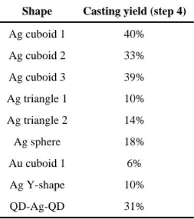
Table 1
Casting yield for different shaped NPs
The casting yield refers to the NP growth yield in step 4 in Fig. 1, and was calculated as the ratio between the number of DNA boxes with metal NPs of designed shapes and dimensions and the total number of seed-decorated DNA boxes. See main text and (29) for details. See table S6 for the yields of each step in constructing the seed-decorated molds, which are not accounted for in calculating the casting yield.
Shape Casting yield (step 4)
Ag cuboid 1 40% Ag cuboid 2 33% Ag cuboid 3 39% Ag triangle 1 10% Ag triangle 2 14% Ag sphere 18% Au cuboid 1 6% Ag Y-shape 10% QD-Ag-QD 31%