READ THESE TERMS AND CONDITIONS CAREFULLY BEFORE USING THIS WEBSITE.
https://nrc-publications.canada.ca/eng/copyright
Vous avez des questions? Nous pouvons vous aider. Pour communiquer directement avec un auteur, consultez la première page de la revue dans laquelle son article a été publié afin de trouver ses coordonnées. Si vous n’arrivez pas à les repérer, communiquez avec nous à [email protected].
Questions? Contact the NRC Publications Archive team at
[email protected]. If you wish to email the authors directly, please see the first page of the publication for their contact information.
NRC Publications Archive
Archives des publications du CNRC
This publication could be one of several versions: author’s original, accepted manuscript or the publisher’s version. / La version de cette publication peut être l’une des suivantes : la version prépublication de l’auteur, la version acceptée du manuscrit ou la version de l’éditeur.
Access and use of this website and the material on it are subject to the Terms and Conditions set forth at
Flanking paths between wood frame walls and floors using statistical
energy analysis
Nightingale, T. R. T.; Steel, J. A.
https://publications-cnrc.canada.ca/fra/droits
L’accès à ce site Web et l’utilisation de son contenu sont assujettis aux conditions présentées dans le site LISEZ CES CONDITIONS ATTENTIVEMENT AVANT D’UTILISER CE SITE WEB.
NRC Publications Record / Notice d'Archives des publications de CNRC:
https://nrc-publications.canada.ca/eng/view/object/?id=87bcca3a-5870-4f55-918c-ba8afe10a29e https://publications-cnrc.canada.ca/fra/voir/objet/?id=87bcca3a-5870-4f55-918c-ba8afe10a29e
Flanking paths between wood frame walls and floors
using statistical energy analysis
Nightingale, T.R.T.; Steel, J.A.
NRCC-47681
A version of this document is published in / Une version de ce document se trouve dans: International Congress on Acoustics, Seattle, WA., June 20-25, 1998, pp. 1389-1390
Flanking Paths Between Wood Frame Walls and Floors Using Statistical Energy Analysis
T.R.T. Nightingale *, John A. Steel †* Institute for Research in Construction, National Research Council, Ottawa, Ontario, Canada, K1M 0R6
† Heriot Watt University, Dept. of Mechanical Engineering, Riccarton, Edinburgh, UK EH14 4AS
Abstract: For the lightweight wood frame constructions considered in this paper, the dominant flanking path is shown to be from the floor decking to the wall below regardless of whether the wall is load-bearing or not. By comparison, the wall -- wall path is shown to be of negligible importance. A theoretical model is developed to predict transmission through the floor/wall joint. Measured and predicted results are in good agreement over the frequency range where flanking transmission is important.
TEST SPECIMENS AND SIMPLIFIED SUB-SYSTEMS
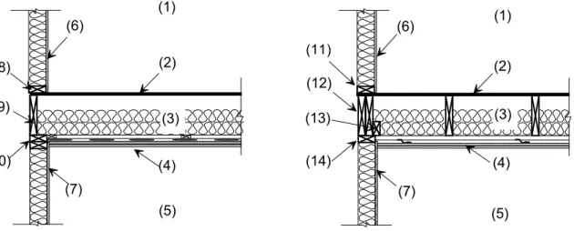
Two complete assemblies were constructed in the IRC Flanking Transmission Test Facilities. Each assembly consisted of a floor/ceiling assembly and two walls, one above and one below the floor as shown in Figure 1. The specimen shown in Figure 1a is referred to as the load-bearing case since the floor joists are at right angles to the specimen wall. The specimen shown in Figure 1b is referred to as the non-load-bearing case as the joists are parallel to the specimen wall which does not take the floor load.
In both cases the basic construction of the floor assembly is identical. The only difference being the orientation of the joists with respect to the specimen wall. However, the joint details are very different. The non-load-bearing case has two beams at the joint (called trimmer joists (12)), a nailing plate to allow the floor strapping to fastened at the joint (13) and there is only a single head plate to the partition wall (14).
(1) (2) (6) (10) (3) (4) (7) (9) (8) (5) (1) (2) (14) (3) (4) (7) (12) (11) (6) (5) (13)
Figure 1a: Section showing construction details of the
load-bearing case and sub-system numbers.
Figure 1b: Section showing construction details of the
non-load-bearing case and sub-system numbers.
(1): source room, (2): 15.9 mm OSB floor decking, (3): 267 mm deep cavity with two layers of 90 mm batt insulation, (4): 2 layers of 12.7 mm type X gypsum board mounted on resilient channels, (5): receive room, (6) and (7): 15.9 mm type X gypsum board, (8): 38x89 mm sole plate, (9): 38x235 mm joist header, (10): double 38x89 mm head plates, (11): 38x89 mm sole plate, (12): double 38x235 mm trimmer joists, (13): 38x89 mm nailing plate, and (14): single 38x89 mm head plate.
MEASURED AND PREDICTED DATA
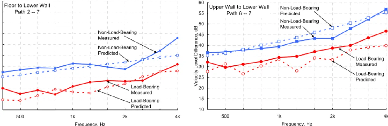
In both cases there are only two flanking paths between the source and receive room; wall – joint – wall (6 – 7) and floor decking – joint – lower wall (2 – 7). There are no flanking paths involving the gypsum board ceiling (4) as it is resiliently mounted to the joists using metal furring strips. In this paper we have restricted ourselves to the frequency range above 400 Hz where flanking paths affected the airborne level difference.
Comparing the measured velocity level differences (VLD’s) given in Figures 2 and 3 for each path it can be seen that regardless of the wall type load-bearing or non, the dominant flanking path is from the floor decking to
the lower wall (2 – 7). It can also be seen that there is considerably less coupling for flanking paths involving the non-load-bearing party wall (6 – 7).
Floor to Lower Wall Path 2 -- 7 10 15 20 25 30 35 40 45 50 55 60 500 1k 2k 4k Frequency, Hz
Velocity Level Difference, dB
Non-Load-Bearing Predicted Non-Load-Bearing Measured Load-Bearing Measured Load-Bearing Predicted
Upper Wall to Lower Wall Path 6 -- 7 10 15 20 25 30 35 40 45 50 55 60 500 1k 2k 4k Frequency, Hz
Velocity Level Difference, dB
Non-Load-Bearing Measured Non-Load-Bearing Predicted Load-Bearing Measured Load-Bearing Predicted
Figure 2: Measured and predicted velocity level difference
between floor decking and the lower party wall (2 – 7) for both the load-bearing and non-load-bearing assemblies.
Figure 3: Measured and predicted velocity level difference
between upper and lower party walls (6 – 7) for both the load-bearing and non-load-bearing assemblies.
Previous work1 to predict the transmission paths involving load-bearing walls indicated that beams at wall/floor joint were very important as they tended to introduce significant high frequency attenuation due to inertia. This work suggested that the best representation for the wall/floor joint was two corner joints sharing a common plate, the floor decking. The upper joint was the floor decking (2) connected to the upper party wall (6) with the sole plate (8) represented by a beam, while the lower was the floor decking (2) connected to the lower party wall (7) with the joist header (9) also represented by a beam. This representation of the wall/floor joint means that vibration energy can not travel directly from upper wall to the lower wall (6 – 7), but rather energy must travel via the floor decking giving the transmission path is 6 – 2 – 7. The predictions shown in Figures 2 and 3 are in good agreement with measured results.
Velocity level difference predictions for paths involving the non-load-bearing party wall are also given in Figures 2 and 3. As before the joint is modelled as two corner joints each having a representative beam. However, the representative beams for the non-load-bearing case are very different. Table 1 shows that the dimensions of the beam for the upper corner joint (connecting 2 and 6) are the same but in the non-load-bearing case the beam has an eccentricity. This means that the axis of joint rotation is offset from the center of the beam. The representative beam used to model elements 12, 13 and 14 in the non-load-bearing case is considerably larger than the representative beam used in load-bearing case. The increased beam dimension along with the introduced eccentricity causes there to be significantly greater attenuation through the lower joint in the non-load-bearing case.
The good agreement between measured and predicted results suggest that, for frequencies above 400 Hz where flanking paths controlled the airborne level difference, the floor/wall joint can be modeled as two corner joints sharing a common plate. Correctly selecting the dimensions and eccentricities of the beams at the joint is critical to the model.
Joint Load-Bearing Wall Non-Load-Bearing Wall
Upper Corner Joint connecting plates 2 to 6
Beam: 38 x 89 mm Ex: 0.0 mm, Ey: 0.0 mm
Beam: 38 x 89 mm Ex: 80 mm Ey: 39 mm Lower Corner Joint
connecting plates 2 to 7
Beam: 38 x 235 mm Ex: 0.0 mm, Ey: 0.0 mm
Beam: 90 x 275 mm Ex: 80 mm Ey: 115 mm
Table 1: Representative beams and eccentricities used in the joint models for the two cases considered in this paper. Ex is the
beam eccentricity in the plane of the plate 2, while Ey is the eccentricity in the plane of plate 6 or 7 for the upper or lower joints, respectively.
REFERENCES
1. Nightingale, T.R.T., Craik, Robert J.M.,. Steel, John A., “Statistical energy analysis applied to lightweight constructions Parts 1, 2, 3,” Canadian Acoustics, Vol. 23, No. 3, pp. 41-47, 1995.