HAL Id: cea-01810068
https://hal-cea.archives-ouvertes.fr/cea-01810068
Submitted on 7 Jun 2018
HAL is a multi-disciplinary open access
archive for the deposit and dissemination of
sci-entific research documents, whether they are
pub-lished or not. The documents may come from
teaching and research institutions in France or
abroad, or from public or private research centers.
L’archive ouverte pluridisciplinaire HAL, est
destinée au dépôt et à la diffusion de documents
scientifiques de niveau recherche, publiés ou non,
émanant des établissements d’enseignement et de
recherche français ou étrangers, des laboratoires
publics ou privés.
Model-Driven Safety Assessment of Robotic Systems
Nataliya Yakymets, Saadia Dhouib, Hadi Jaber, Agnes Lanusse
To cite this version:
Nataliya Yakymets, Saadia Dhouib, Hadi Jaber, Agnes Lanusse. Model-Driven Safety Assessment of
Robotic Systems. 2013 (IEEE/RSJ) International Conference on Intelligent Robots and Systems, Nov
2013, Tokyo, Japan. �cea-01810068�
2013 IEEE/RSJ International Conference on Intelligent Robots and Systems (IROS) November 3-7, 2013. Tokyo, Japan
Model-Driven Safety Assessment of Robotic Systems
N . Yakymets, S. Dhouib, H. Jaber, A. LanusseAbstract— Robotic systems (RSs) are often used for
performing critical tasks with little or no human intervention. Such RSs must satisfy certain dependability requirements including reliability, availability, security and safety. In this paper, we focus on the safety aspect and propose a methodology and associated framework for safety assessment of RSs in the early phases of development. The methodology relies upon model-driven engineering approach and describes a preliminary safety assessment of safety-critical RSs using fault tree (FT) analysis (FTA). The framework supports a domain specific language for RSs called RobotML and includes facilities (i) to automatically generate or manually construct FTs and perform both qualitative and quantitative FTA, (ii) to make semantic connections with formal verification and FTA tools, (iii) to represent FTA results in the RobotML modeling environment. In the case study, we illustrate the proposed methodology and framework by considering a mobile robot developed in the scope of the Proteus project.
I. INTRODUCTION
Modern robotic systems (RSs) are complex and capable to perform sophisticated tasks in different domains [1][2]. In order to cope with system complexity, engineers consider new approaches to system development based on formalized modeling [3]. Model-driven engineering (MDE) is expected to significantly simplify the support of system requirements, design, analysis, verification and validation through a system life-cycle. The use of system level models enables simulation of the overall performance and behavior of complex RSs. In addition, MDE gave birth to domain specific languages like Robotic Modeling Language (RobotML) [4] to target system development in different domains. RobotML is built as a UML profile to design, simulate and deploy robotic applications. RSs can be defined using appropriate RobotML notations, abstractions and facilities to automatically generate executable code. RobotML could be a solution for robotics experts to deal with variability problems and to hide the lower level programming details.
N. Yakymets is with the CEA, LIST, DILS, Laboratory of model driven engineering for embedded systems - Point Courrier 174, Gif-sur-Y vette, 91191, France (e-mail: nataliya.yakymets@ cea.fr).
S. Dhouib is with the CEA, LIST, DILS, Laboratory of model driven engineering for embedded systems - Point Courrier 174, Gif-sur-Yvette, 91191, France (e-mail: nataliya.yakymets@ cea.fr).
H. Jaber was with the CEA, LIST, DILS, Laboratory of model driven engineering for embedded systems - Point Courrier 174, Gif-sur-Yvette, 91191, France. He is now with the Laboratoire Génie Industriel, Ecole Centrale Paris, Grande voie des vignes, 92290 Chatenay-Malabry, France (e-mail: [email protected]).
A. Lanusse is with the CEA, LIST, DILS, Laboratory of model driven engineering for embedded systems - Point Courrier 174, Gif-sur-Yvette, 91191, France (e-mail: agnes.lanusse@ cea.fr).
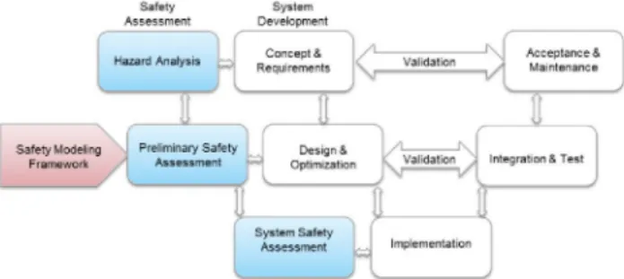
Our research has been inspired by RSs for safety-critical applications. Such RSs as [1] or [2] are expected to satisfy a high level of safety. Standards [5] [6] concerned with the development of safety-critical systems require an application of specific design flows where system engineering is conducted in parallel with safety assessment (SA) as shown in Figure 1. This allows the concept, design and implementation of safety-critical RS to be developed with respect to the safety aspects. Each phase of SA flow implies application of a set of specific methods and activities. Typical SA methods include preliminary and system hazard and risk analysis [7], fault tree (FT) generation and analysis (FTA) [8], failure mode and effects analysis (FMEA) [9]. Although these well-established methods provide an efficient support for safety engineers, they could greatly benefit from a tighter coupling with system modeling environments. MDE offers facilities to annotate models with information needed for SA, to perform validation according to dedicated rules, to write transformation rules towards formal languages to permit their analysis by formal tools. It becomes thus possible to perform model-driven SA by incorporating existing SA methods and tools into a uniform MDE environment.
Safety
Assessment Development System Concept &
Requirements
c
Acceptances Va iterance Safety Modeling Preliminary Safety Designi / *-Framework Assessment Optimization \ ,V; Integration S Test
System Safety Assessment
Figure 1. SA-based life-cycle of system development
In this paper, we aim to contribute to integration of SA techniques and standards into the MDE environment based on RobotML. Certain efforts have already been put into investigation of possible ways of SA through the MDE process based on the general purpose System Modeling Language (SysML) [10]. Similar studies are also undertaken with other modeling languages such as architecture description language for automotive embedded systems (EAST-ADL) [11] or architecture analysis and design language (AADL) [12]. However, these languages are limited for RS design compared to the domain specific RobotML language.
We propose a methodology and associated framework for model-driven analysis of RSs in the preliminary SA phase (Figure 1. ). The safety standards for robotics are not mature enough and some of them [13] have been still under development. Therefore the methodology follows the
IEC61508 [5], a generic standard on functional safety design, and describes S A using F T A approach. It leverages features of RobotML (i) to capture information required for formal analysis (ii) to propagate S A results back into the M D E environment. The framework includes metamodels, profiles, model transformation and F T generation plug-ins, tools for formal verification and F T A . The use of the proposed methodology and framework allows the safety engineer to start S A from the early phases of R S development which can significantly reduce time and cost constraints.
We discuss a case study called Robotic Young Challenge (RYC) which has been designed by the Proteus1 project partners. R Y C addresses problems of autonomous motions of mobile robots in unknown structured environment. Its main functionality is outdoor exploration and target searching. Using this case study, we perform preliminary S A by F T generation and further qualitative and quantitative F T A according to IEC61508. We also show how to use RobotML-based M D E environment to describe possible effects of failures (or dysfunctional behavior) of the Proteus R Y C robot and to display generated FTs and F T A results.
The remainder of the paper is organized as follows. In section II, we analyze existing methods and tools for S A . Then we introduce our S A methodology and toolset for RSs in sections III. In section IV, we present the case study on S A and conclude in section V .
II. RELATED WORKS AND PAPER CONTRIBUTION
In our research we focus on the preliminary S A phase of S A flow shown in Figure 1. The goals of this phase are (i) to evaluate R S architecture with respect to the list of possible hazards obtained from the hazard analysis phase and (ii) to derive safety requirements. R S architecture can be evaluated using such methods as F T A [8][14][15],
F M E A [9][16], event tree analysis, etc. F T A and F M E A are complementary methods aiming to analyze propagation of faults through the system. F M E A is an inductive bottom up method used to analyze a system on component level and check what happens on system level. F T A , a deductive top-down method, does the opposite by defining a state on system level and checking what can cause this at component level. In practice, F T A is performed on larger systems, which makes it more suitable for S A of complex RSs.
F T A was originally developed by H.A. Watson in 1962 at Bell Laboratories [17]. A typical F T consists of the top event and a set of basic and house events organized with the logic gates (AND, O R , etc.). The qualitative analysis of F T aims to find all the minimal combinations of basic events (called minimal cut sets) resulting in the top event. The F T quantitative analysis is also often used in probabilistic computation.
The F T generation approaches fall into several categories depending on the method used to annotate a system with its dysfunctional behavior. Structured
1 http://www.anr-proteus.fr
approaches [8][18] use manually created models of failure behavior. Such approaches are time consuming and rely upon the ability of the safety engineer to predict the system behavior and may lead to higher probability of errors. Another group of approaches is based on the decision table method [19]. They are quite efficient for small and middle range systems but may require sophisticated tables for the large systems with complex multi-level hierarchy. Approaches based on failure modes injection extend each component of the nominal system model with a set of possible failure modes and then model the system dysfunctional behavior using such an extended model. The tools based on these approaches (for example, FSAP/NuSMV [20]) translate an extended model into a state machine and then use formal verification algorithms to generate minimal cut sets and construct FTs. In the case of complex systems, however, the application of such approaches may result in combinatorial explosion when the number of failure modes in state machines grows. Some FT generation approaches are based on failure logic modelling. These approaches use analytical expressions associated with the system components to model the possible propagation of failures. HiP-HOPS [21] or SafetyArchitect2 tools support failure logic modelling.
T A B L E I. METHODS AND TOOLS FOR F T A
Tools SA FT generation method Support of hierarchical systems FTA Formal verification Input language Saml MIN. CUT SETS V S V Saml KB3 Ma-nual -</ - Figa-ro HiP-Hops Analy-tical expr. • </ -Matlab EAST-ADL FS AP/Nu SMV Min. cut sets V S V SMV Our MSA framework Analytical expr., Min. cut sets • </ V RobotML, AltaRica, OpenPSA
The comparative analysis of existing approaches and tools for FT generation and analysis is given in TABLE I. We list here only academic approaches, since industrial solutions generally rely on a part of them. Although some of these tools [20][21] perform automatic FT generation, their capabilities are limited for SA of complex RSs. First, they lack convenient representation of the input system models. For example, FSAP/NuSMV, SAML [22] or ARC3 tools use formal symbolic languages such as SMV, SAML [22] or AltaRica [23] to describe a system. This might require certain time efforts from the SA engineer to formulate and enter the model in these formats. Second, they lack a convenient representation of the final results of SA. In HiP-HOPS, for instance, safety annotations can be entered through a profile of the EAST-ADL implementation in the Papyrus4 tool, but there are no elaborated mechanisms to
http://all4tec.net/index.php/en/model-based-safety-analysis/25-safety-architect-a-mbsa-tool
http://altarica.labri.fr/forge/projects/arc/wiki http://www.eclipse.org/modeling/mdt/papyrus/
show the results of conducted SA in the system modeling environment.
In this work, we analyze the possibilities of using different methods and tools for model-driven SA during the early phases of RS development. The IEC61508 standard [5] refers to FTA as a recommended technique to perform SA in the design phase of system life-cycle. We propose a methodology to perform a preliminary SA of RSs using FTA and then to derive the obtained results back into the RobotML model. To automatically generate FTs from RobotML models, we combine the approach based on analytical expression of dysfunctional behavior with formal verification based on AltaRica language. The AltaRica model is automatically generated from the RobotML annotated model using transformation rules. The methodology was implemented in a framework which integrates formal verification and FTA algorithms in the MDE environment supported by the Papyrus editing tool for RobotML. The framework contains model transformation and FT generation plug-ins, as well as profiles for model annotation and FT visualization. The qualitative and quantitative FTA is carried out with built-in ARC and
XFTA5 engines.
In the next sections, we shall describe the methodology and framework, and show how they can be used for SA of RSs.
III. METHODOLOGY AND FRAMEWORK
The methodology is dedicated to the preliminary SA of safety-critical RSs. Figure 2. illustrates the SA flow based on the use of the proposed methodology. The following information is taken as input data:
• the SA recommendations taken from the IEC61508 standard;
• the list of possible hazards derived from the hazard analysis phase of SA flow;
• the system architecture defined as a multi-level network of RobotML components like Sensors, Actuators, etc.
RobotML Model IEC6150S Possible hazards . A ψ *.uml X
Model Annotation ψ *.uml Model Translation from RobotML to Altarica
vjr '.alt Fault Tree Generation
ψ *.psa Qualitative &. Quantitative
FTA ψ *.uml, *.txt Delivery of FTA Results to
RobotMLModel
Figure 2. The SA methodology
First, a RS is designed with the Papyrus platform using RobotML language. Second, we define the sufficient finest level of RS architecture where SA will be conducted and then annotate a RobotML model with the possible failure behavior at this level. While defining failure modes of the components, information on the possible hazards derived from the hazard analysis is taken into account. RS dysfunctional behavior is annotated using analytical expressions. Once the annotation has been done, the failure states and events related to the component failure modes are automatically extracted, and the RobotML model is converted into the AltaRica language. The checking of the AltaRica model is performed by the ARC tool. This tool also computes minimal cut sets for the considered model. Based on this information we automatically generate FTs
and represent them in the Open-PSA format6 . Finally, we
perform FT qualitative and quantitative analysis according to IEC61508 and compute a set of factors (like probability of the top FT event, contribution of minimal cut sets, etc.) to evaluate system safety. In order to make SA results more representative, we display FTs in RobotML modeling environment with FT profile.
The complexity of the proposed methodology is strongly linked to the number of levels in the system hierarchy and to the scalability of the formal verification tool used. If the number of potential failure modes increases, the risk of combinatorial explosion is higher. The proposed methodology provides a possibility to control the granularity of SA through the assessment process by choosing the finest level of RS architecture where the components are annotated with the dysfunctional behavior. Therefore it is a flexible instrument to control the number of failure modes and to decrease the risk of combinatorial explosion. Eclipse + Papyrus Fault Tree Profile k J Operi-PSA Meta-model RobotML Profile Annota tion Profile . AltaRica Meta-model
I )
i l
XFTA -FT quantitative analysis Fault Tree Generator ScriptGenerator AltaRica Converter RobotML to
"-··.
To £
ARC/AltaRica -Minimal cut sets generation
Figure 3. The architecture of the framework
The architecture of our framework is represented in Figure 3. It has been implemented using java under Eclipse Modeling Framework (EMF). The framework contains two sets of tools including safety profiles and metamodels and tools for SA at the preliminary SA phase including FT generation and analysis.
In order to illustrate the proposed SA methodology and framework as clearly as possible, we consider the example of ' http://www.lix.polytechnique.fr/~rauzy/xfta/xfta.htm ' http://www.open-psa.org
a mobile robot and go through the safety modeling flow associated with our approach in the next section.
IV. CASE STUDY
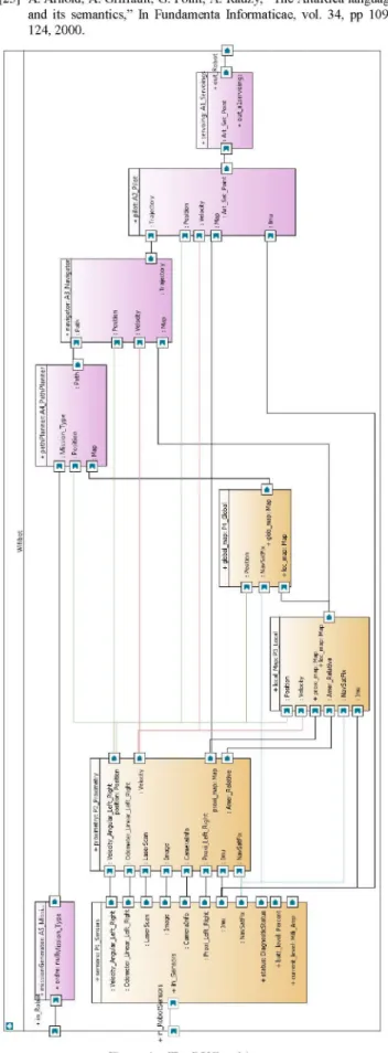
We validate the methodology and framework described in the previous sections by analyzing one of the case studies developed in the scope of the Proteus project. The considered example is a scenario defined by Robotic Youth Challenge (RYC) and deployed in a WifiBot robot7. The R Y C targets autonomous motion of mobile robots in unknown structured environment. The main scenario for the robot is outdoor exploration and target searching. The R Y C architecture developed in RobotML using RobotML modeling environment is shown in Figure 4. The top hierarchical level includes nine components: Mission
Generator generates R Y C missions, Path Planner
calculates a path for the R Y C robot using the global map and information on current mission and position, Navigator delivers local trajectory for the pilot taking into account the local map, Pilot calculates the left and right wheel speed setpoints that the robot is supposed to reach to follow the input trajectory, Servoings transforms the speed commands to the format (tics) used by the wifibot robot, Sensors captures information on surrounding environment,
Proximetry builds a map in polar coordinate with only
meausres from sensors directly printed in it, Local Map builds a relative Cartesian 2D map with obstacles placed in it, Global Map builds an absolute map of the scene.
In this example, we consider a hazardous event when "The RYC robot does not follow the commands". In other words, this will be a top event of the tree.
A. Model Annotation
The R Y C model described in RobotML is annotated with failure behavior. Information on hazards, derived from the hazard analysis according IEC61508, is taken into account while defining possible failures of R Y C components. The dysfunctional behavior is represented as a set of analytical expressions showing how deviations in the component outputs can be caused by internal failures of the component and/or possible deviations in the component inputs. Only components of the finest level defined for S A (or basic components, BCs) are annotated with the analytical expressions. For example, the output deviation expression for the output Path of the B C called Path
Planner (Figure 4. ) has the following format:
(NOT f) AND Mission_Type AND Position AND Map.
It means that the output Path does not propagate failure behavior if (i) there is no failure/ "Path Planner internal
failure" of the component Path Planner and (ii)
information on the input ports Mission_Type, Position and
Map is correct.
The dysfunctional behavior of the components representing higher hierarchical levels is simulated by model checking engine. It is a composition of state machines obtained after model transformation into the
http://www.wifibot.com
AltaRica language from the output deviation expressions of BCs.
We assign output deviation expressions using a UML profile mechanism in Papyrus environment. The framework contains an annotation profile enabling to stereotype each BC output port with deviation expressions. During the model translation process, the failure states and events related to the RYC components are automatically extracted from these expressions.
B. Model Translation
The next step is to extract information on the failure states and events from the output deviation expressions and to convert the RobotML model into the AltaRica language. The transformation method used for conversion of RobotML model to AltaRica language relies upon the MDE approach. TABLE II. lists the mapping we defined for our transformation algorithm implemented in the framework.
T A B L E II. TRANSFORMATION RULES
Concept Component type Component /Prototype Flow variable /Type /Direction Connection components Output deviation expression RobotML Robot
Software, Hardware, RoboticSystem, SensorSystem, ActuatorSystem, CameraSystem, GPSSystem, Object-DetectionSensorSystem, Sensor-Driver, ImageSensorSystem, EngineSystem, WheelSystem, ObjectTrackingSensorSystem, LocalizationSensorSystem, SimulatedSystem Part DataFlowPort / Type / Direction Connector Stereotyped DataFlowPort AltaRica Node main Node Field:sub Field: Flow /bool,integer, float,domain /In , Out Assertion Failure states and events, output assertions Descr. RS under analysis RS components RS ports Connection between components Component failure behavior By default, we assume that the RYC robot is operating normally. Consequently, all extracted failure states associated with BCs (or nodes in AltaRica) are initialized as
"false" in AltaRica. Based on information on the extracted
failure states, we create a set of events resulting in the occurrence of these states and then generate appropriate transactions. The declaration of the main node in AltaRica model relies upon information extracted from RobotML top architecture diagram: the system parts are translated into sub-nodes connected via assertions.
C. Fault Tree Generation and Analysis
In this phase RYC is assessed by using FTA method. The framework uses integrated model checking engine called ARC and script generator to compute minimal cut sets for a considered top event. Then FT is built with FT generator. We consider only static FTs, however, the ARC engine can provide the facilities to further analyze a dynamic behavior of RSs.
FT generation includes several steps. First, we obtain all possible minimal combinations of component failures violating a given failure event. Second, we group these combinations, called minimal cut sets, in a tree structure as
follows. The events from each minimal cut set are considered as basic and grouped using A N D gate. Then we connect all the A N D gates to the O R gate which, in turn, is linked to the top event.
The qualitative F T A has shown that the top event "The RYC robot does not follow the commands" occurs if any sequence of basic failure events given in T A B L E III. occurs. Once a F T has been obtained, we carry out a quantitative F T A using integrated X F T A engine. This
engine performs quantitative analysis of FTs and provides information on the top event probability for different mission times, importance factors of basic events, common cause failure analysis, etc. According to the standard IEC61508, we assess the probability of the considered top event based on the statistical data on failure rates of basic events of the considered components. In addition, the probability and contribution of each minimal cut set are computed (TABLE III. ). Moreover, we define the most critical part of R Y C , the Sensors sub-system, since its failure has the highest impact on the failure of the whole
RS.
D. Propagation of FTA Results
The automatically generated F T can be either represented in open-PSA format, the F T specific format developed for describing complex FTs, or in a graphical form via dedicated profile. By using the F T profile, we can present FTs that consist of basic, house and top events organized with A N D or O R gates, as well as F T A results. Thus, the use of such a profile helps to construct FTs in RobotML/Papyrus environment and provides a better connection between system functional and dysfunctional behavior through M D E .
V . CONCLUSION
In this work, we propose the methodology and framework which provide a support for safety engineers by integrating safety techniques within a model-driven engineering process. The methodology relies on the generic standard on functional safety design IEC61508 and shows how to automate safety assessment process of robotic systems in the early development phases. The use of the proposed methodology aims to fill the gap between system modeling and safety assessment tools and helps to better cope with system engineering time and cost constraints. Indeed, the results of preliminary safety assessment can reveal the most safety-critical parts of the system which should be mitigated.
To implement the proposed methodology, we develop a safety modeling framework which automates safety assessment of robotic applications in the RobotML-based modeling environment. The framework is an alternative to such safety assessment tools as HiP-HOPS, FSAP/NuSMV, KB3, S A M L . As opposed to these tools, the framework is oriented to the robotic domain and provides the facilities of RobotML domain specific language to develop safety-critical robotic applications. Furthermore, the framework supports a common system model for system and safety
engineers, by using U M L profile mechanisms in Papyrus. This allows to integrate all data linked with safety assessment in the same system model, as well as to customize an interface to show different results within one uniform environment and reuse this information for further reliability studies.
ACKNOWLEDGMENT
The authors thank Hadi Jaber for his strong contribution to this work during his internship in CEA.
REFERENCES
[I] J J . Biesiadecki, M.W. Maimone, "The Mars exploration rover surface mobility flight software: driving ambition," IEEE Aerospace Conference Proceedings, March 2006, Montana, U S A .
[2] A. Rankin, C. Bergli, S. Goldberg, and L. Matthies, "Passive perception system for day/night autonomous offroad navigation," In SPIE U G V Symposium, Orlando, FL, April 2005.
[3] J. A. Estefan, "Survey of model-based Systemse (MBSE) methodologies," Rev A, Incose MBSE Focus Group, 2007.
[4] S. Dhouib, S. Kchir, S. Stinckwich, T. Ziadi, M. Ziane, "RobotML, a domain-specific language to design, simulate and deploy robotic applications," Int. Conference on Simulation, Modeling and Programming for Autonomous Robots, pp. 149-160, 2012.
[5] I E C , 61508: 1998 and 2000, part 1 to 7. Functional safety of electrical, electronic and programmable electronic systems, 2000. [6] ARP-4754: Certification considerations for highly-integrated or
complex aircraft systems, Society of Automotive Engineers (SAE) standard, 1996.
[7] IEC 61882: Hazard and operability studies, application guide, 2001. [8] Fault tree handbook with aerospace applications. N A S A , 2002. [9] I E C 60812: Analysis techniques for system reliability - Procedures
for F M E A , 1985.
[10] P. David et al., "Reliability study of complex physical systems using SysML," Reliability Engineering and system Safety, Elsevier, pp. 431-450, 2010.
[II] P. Cuenot, D J . Chen, S. Gerard, H. et al. Towards improving dependability of automotive systems by using the E A S T - A D L architecture description language. Architecting Dependable Systems IV, Lecture Notes in Computer Science, vol. 4615, pp, 39-65, 2006. [12] P. H. Feiler, D. P. Gluch, "Model-based engineering with AADL: an
introduction to the S A E architecture analysis & design language," Addison-Wesley Professional, 1st ed., pp. 496, 2012.
[13] ISO/FDIS13482: Robots and robotic devices - Safety requirements for non-industrial robots - Non-medical personal care robots (Final Draft International Standard).
[14] C. Carreras, I.D. Walker, "Interval methods for fault-tree analysis in robotics," IEEE Trans. on Reliability, Vol. 50, No. 1, 2001, pp. 3-11. [15] I.D. Walker, J.R. Cavallaro, "Failure mode analysis for a hazardous clean-up manipulator," Reliability Engineering and System Safety, Special Issue on Safety of Robotic Systems, Vol. 53, No3, September 1996, pp. 277-290.
[16] M.L. Visinsky, J.R. Cavallaro and I.D. Walker, "Robotic fault detection and fault tolerance: a survey," Reliability Engineering and System Safety, Vol. 46, #2, 1994, pp. 139-158.
[17] C. Ericson, "Fault Tree Analysis - A History," Proceedings of the 17th International Systems Safety Conference, 1999.
[18] I. Renault, et al.,"KB3: computer program for automatic generation of fault trees," Rei. Maintain. Symp., pp. 389 -395, 1999.
[19] J. D. Andrews, J. J. Henry, "A computerized fault tree construction methodology," in Proc. of the Institution of Mechanical Engineers, 1997; 211(E), pp. 171-183.
[20] M. Bozzano, Ch. Jochim, "The FSAP/NuSMV-SA safety analysis platform," Int. Journal on Software Tools for Technology Transfer, 2007,v.9, Noi, pp. 5-24.
[21] M. Walker et al., "Compositional temporal fault tree analysis. Computer safety, reliability, and security," Lecture Notes in Computer Science, vol. 4680, 2007, pp. 106-119.
[22] M. Gudemann, F. Ortmeier, "A Framework for qualitative and quantitative formal model-based safety analysis," In Proc. 12th IEEE High Assurance Systems Engineering Symp., pp. 132-141, 2010. [23] A Arnold, A. Griffault, G. Point, A. Rauzy, "The AltaRica language
and its semantics," In Fundamenta Informaticae, vol. 34, pp 109-124, 2000.
TABLE III. FAULT TREE ANALYSIS RESULTS
Qualitative FTA N 1 2 3 4 5 6 7 8 9 10 11 12 13 14 15 16 17 18 19 20 21 22 23 24 25 26 27 28 29 30 31 32
Minimal Cut Set
(sensors.camera_FireWire.Incorrect_video_c apturing_occurs,
sensors .camera_FireWire. Incorrect_calibratio n occurs) (sensorsxarnera_FireWire.mteraal_Camera_f ailure_occurs) (sensors.LaserRange.Incorrect_laser_scan_oc curs) (pilot.pilot.Pilot_doesnt_avoid_obstacles_see n in approximetric map occurs) (pilot.pilot .Pilot_follows_wrong_tr ajectory_ when_calculaÜng_set_points_in_operating_sp ace occurs) (pilot.iKM. IKM_doesnt_transform_velocities _from_operational_to_articular_space_occurs ) (navigator.navigator.Incorrect_velocity_analy sis_occurs, navigator.navigator.Incorrect_position_analys is_occurs, navigator.navigator.Incorrect_local_map_ana lysis_occurs, navigator.navigator.Incorrect_path_analysis_ occurs)
(navigator .navigator .Internal_failure_of_Navi gator_occurs)
(missionGenerator.mission.internalFailure_oc curs)
(sensors.wifibot_Frame_Out.internalFailure_ occurs)
(sensors. odometer .intemalFailure occurs) (proximetry. amer_I dentif. Incorr ect_interpr eta tion camera results occurs)
(proximetry. amer_I dentif. Intemal_failur e_Am er Identif occurs)
(proximetry.proximetric_Map.Incorrect_bit_ map generation occurs)
(proximetry.proximetric_Map.Internal_failure Proximetric Map occurs)
(sensors.IMU.internalFailure occurs) (proximetry. super DKM .internalFailure_occur s)
(pathPlanner.path_Planner.Wrong_path_gene ration based on correct input data occurs) (pathPlanner .path_Planner. Intemal_failure_of
Path Planner occurs)
(proximetry. super DKM. Wrong_velocity_calc ulation using correct input data occurs) (proximetry. super DKM. Wrong_position_calc ulation using correct input data occurs) (proximetry. super DKM. Intemal_failure_Supe r DKM module occurs)
(local_Map. amer_Loc. Intemal_failure_Amer Relative occurs)
(local_Map.local_Map.Incorrect_analysis_of_ proximetric_map_occursf
local_Map local_Map. Incorrect_analysis_of_ GPS_data_occurs,
local_Map.local_Map. Incorrect_analysis_ofv elocity_occurs,
local_Map local_Map. Incorrect_analysis_of_ position occurs)
(local_Map.local_Map.Memory_failure_occu rs)
(local_Map.local_Map.Internal_failure_Local Map occurs)
(global_map. global_Map. Incorrect_analysis_ of_position_data_occursf
global_map.global_Map.Incorr ect_analysis_o f_local_map_data_occursf
global_map.global_Map.Incorr ect_analysis_o f GPS data occurs)
(global_map. global_Map. Intemal_failure_of_ GlobalMap module occurs)
(sensors.GPS.Internal GPS failure occurs) (in Robot. isAbsent)
(servoing.servoings. Incorrect_interpr etation_ of_command_Left_occurs,
servoing. servoings .Incorr ect_interpretation_o f command Right occurs)
(servoing.frame_In.Internal_failure_of_modul e WifiBot Frame In occurs)
Top Event
The RYC robot does not follow the commands
Quantitative FTA Probability 0.0000045 0.008 0.004 0.0065 0.003 0.002 0.0015 0.005 0.002 0.003 0.0015 0.005 0.003 0.0065 0.006 0.001 0.007 0.003 0.0065 0.003 0.0035 0.006 0.005 0.0000157 0.007 0.0015 0.0000167 0.004 0.008 0.005 0.0000385 0.0045 Contribution 0.0000370239 0.0658203 0.0329102 0.053479 0.0246826 0.0164551 0.0123413 0.0411377 0.0164551 0.0246826 0.0123413 0.0411377 0.0246826 0.053479 0.0493652 0.00822754 0.0575928 0.0246826 0.053479 0.0246826 0.0287964 0.0493652 0.0411377 0.00011565 0.0575928 0.0123413 0.00005877 0.0329102 0.0658203 0.0411377 0.00031676 0.0370239 Probability 0.121543
Figure 4. The RYC architecture