HAL Id: hal-00860909
https://hal.inria.fr/hal-00860909
Submitted on 17 Sep 2013
HAL is a multi-disciplinary open access
archive for the deposit and dissemination of
sci-entific research documents, whether they are
pub-lished or not. The documents may come from
teaching and research institutions in France or
abroad, or from public or private research centers.
L’archive ouverte pluridisciplinaire HAL, est
destinée au dépôt et à la diffusion de documents
scientifiques de niveau recherche, publiés ou non,
émanant des établissements d’enseignement et de
recherche français ou étrangers, des laboratoires
publics ou privés.
A Component-Based Approach for Specifying Reusable
Visual Languages
Amine El Kouhen, Sébastien Gerard, Cedric Dumoulin, Pierre Boulet
To cite this version:
Amine El Kouhen, Sébastien Gerard, Cedric Dumoulin, Pierre Boulet. A Component-Based Approach
for Specifying Reusable Visual Languages. 2013 IEEE Symposium on Visual Languages and
Human-Centric Computing, Allen Cypher, Sep 2013, San José, CA, United States. pp.135-138,
�10.1109/VL-HCC.2013.6645257�. �hal-00860909�
A Component-Based Approach for Specifying
Reusable Visual Languages
Amine El Kouhen and S´ebastien G´erard
CEA LIST, Laboratory of Model Driven Engineering for Embedded Systems
Gif-sur-Yvette, France
Email: {amine.elkouhen, sebastien.gerard}@cea.fr
C´edric Dumoulin and Pierre Boulet
University of Lille, LIFL CNRS UMR 8022 Cite scientifique - Bˆatiment M3, Villeneuve d’Ascq, France
Email: {cedric.dumoulin, pierre.boulet}@lifl.fr
Abstract—Model-Driven Engineering (MDE) encourages the use of graphical modeling tools, which facilitate the development process from modeling to coding. Such tools can be designed using the MDE approach into metamodeling environments called metaCASE tools. It turned out that current metaCASE tools still require, in most cases, manual programming to build full tool support for the modeling language, especially for users’ native methodologies and representational elements and suffer from gaps in terms of reusability. In this context, we propose MID, a set of metamodels supporting the specification of modeling editors by means of reusable components and explain how representational metamodeling is carried out with it.
I. INTRODUCTION
As part of its Model-Driven Architecture (MDA) initiative, the Object Management Group (OMG, http://www.omg.org) -an international consortium representing numerous industrial and academic institutions - has provided a comprehensive series of standardized technology recommendations in support of model-based development of both software and systems in general. These cover core facilities such as metamodel-ing, model transformations, and general-purpose and domain-specific modeling languages. A key component in the latter category is UML (the Unified Modeling Language), which has emerged as the most widely used modeling language in both industry and academia. A number of tools supporting UML are available from a variety of sources. These are generally proprietary solutions whose capabilities and market availability are controlled by their respective vendors. Consequently, some industrial enterprises are seeking open-source solutions for their UML tools. To respond to this requirement, a new graph-ical editor called Papyrus, was accepted by the Eclipse Project MDT in August 2008. This graphical editing tool for UML2 is based on Eclipse and uses the Eclipse graphical modeling Framework (GMF, http://www.eclipse.org/modeling/gmf/).
Papyrus is a tool consisting of several editors, mainly graphical editors but also completed with other editors such as textubased and tree-based editors. All these editors al-low simultaneous viewing of multiple diagrams of a given UML model. However, when such diagrams were specified, we found common problems at different levels. The first common point relates to the redundant elements in all UML diagrams, such as Comments or Constraints elements that are presents in all Papyrus diagrams. The second common point relates to some specific diagrams as Package Diagram, which is composed of a Class Diagram subset (Package, import,
merge...). The other common point relates to the graphical variation of several features. For example, a Class in the class diagram does not have the same graphical representation as in the composite structure diagram. These elements have the same semantics in the UML model, sometimes they have the same graphical structure, but they are represented with different shapes. This statement raises a real issue of reuse when specifying diagrams.
To explain these issues, we evaluated the technologies currently used to specify Papyrus diagrams [1]. It turns out that the main reason for these gaps is the lack of reusability in this kind of technology. This leads in manual copies in all diagrams, thus increasing the risk of errors, problems of consistency, redundancy in the specification and the difficulty of maintenance.
At a high level of abstraction, the study of these tools, and especially GMF, allows us to identify some needs and criteria in terms of reusability, graphical completeness, model consistency and maintainability of diagrams specifications. Compliance with these criteria led us ultimately to produce an alternative meta-tool based on a set of metamodels called MID (Metamodels for user Interfaces and Diagrams), to rapidly design, prototype and evolve graphical editors for a wide range of visual languages. We base MID’s design on three overar-ching requirements: graphical completeness, ease of use and simplicity of (de)composition of diagrams editors for a better reusability. For that, we take advantage from MDE benefits, Component-based modeling and an inheritance mechanism to increase the reuse of editors’ components. The main goal of this work is the specification of UML-like modeler as Papyrus [2], from reusable pre-configured components.
II. FOUNDATIONS ANDRELATEDWORKS
In this section, we present the state of the art of graph-ical modeling environment. We begin by presenting visual representation foundations to extract concepts that describe a diagram and then studying several existing methods and tools for specification and generation of graphical editors for diagrams. This study has identified several issues, which we expound as evaluation criteria for our approach.
A. Visual Languages Basics
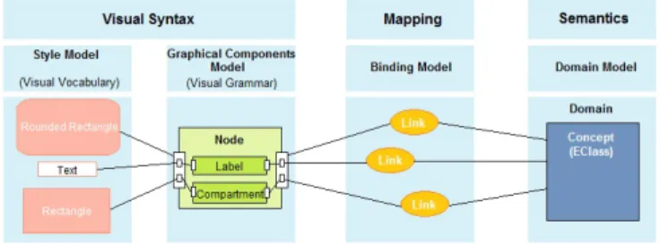
According to [3], elementary components of a visual repre-sentation are called visual notations (visual language,
diagram-ming notations or graphical notations) and consist of a set of graphical symbols (visual vocabulary), a set of compositional / structural rules (visual grammar) and definitions of the meaning of each symbol (semantics). The visual vocabulary and visual grammar form together the concrete (or visual) syntax.
Graphical symbols are used to symbolize (perceptually represent) semantic constructs, typically defined by a meta-model [4]. The meanings of graphical symbols are defined by mapping them to the constructs they represent. A valid expression in a visual notation is called a visual sentence or diagram. Diagrams are composed of symbol instances (tokens), arranged according to the rules of the visual grammar [3]. Such distinction between the content (semantics) and the form (syntax: vocabulary and grammar), allows us to separate the different concerns of our proposition. These definitions are illustrated in fig. 1.
Fig. 1. The nature of a visual notation [3]
The set of visual variables define a vocabulary for graphical communication: a set of atomic building blocks that can be used to construct any graphical representation. Different visual variables are suitable for encoding different types of information. The choice of visual variables has a major impact on cognitive effectiveness as it affects both speed and accu-racy of interpretation [5], [6], [7]. Bertin [8] identified eight elementary visual variables, which can be used to graphically encode information. These are categorized into planar variables (the two spatial dimensions x,y) and retinal variables (Shape, Color, Size, Brightness, Orientation, Texture).
B. Evaluation Criteria
Many frameworks, meta-tool environments and toolkits have been created to support the development of visual lan-guage environments. The diagrams specification methods have been widely discussed in [1], [4], [9]. This article focuses on the criterion of reusability that we consider very useful in the context of diagrams specification. Among the forms of reuse, we can cite the separation of concerns, inheritance and overloading.
Most of diagrams specification methods mix concerns. The most common form of this mixture is that of form and content (visual representations and semantics). For example, in the case of diagram specification using GME [10] or MetaEdit+[11], these tools allow creating the specific concepts and their asso-ciated representations in the same repository. This weakens the required loosely coupling relationship between the semantics and the graphical aspects. The same problem is observed with Obeo Designer, which allows graphical/semantics association in the same model.
Other form of mixing is between the visual vocabulary and visual grammar definition. Most of the tools offering the separation of the graphical part from the semantic one, as GMF tooling, TopCased-Meta and even standards like Diagram Definition, fail to separate the two graphical syntax concerns, which are visual vocabulary (shapes, colors, styles ...) and visual grammar (structure and composition of representations). III. PROPOSAL: METAMODELS FOR USERINTERFACES
ANDDIAGRAMS(MID)
The aim of our work is to design diagram editors and to allow reusing parts of such design. For that, we propose to use a Model-driven approach, to ensure the independence to tech-nology, ease the maintenance and enable better sustainability. To improve reusability, we propose a component-based ap-proach. This approach aims to take advantage of encapsulation (ease of maintenance and composition) and the benefits of interfacing (interfaces naming mechanism). In addition, our approach allows the reuse through inheritance: a component can inherit from another one and it can also override some of its characteristics (style, structure, mapping...). The inheritance of a component is done by the reuse of its interface respecting the naming of the latter.
Fig. 2. MID: Involved Artifacts relationship
Figure 2 shows the linkage of the metamodels involved in our proposal. First, we separate the domain content (semantics) and the form (visual syntax or concrete syntax) of a diagram at a high level of abstraction (language level). The Semantics is out of scope of our paper, it is widely treated in tools and technologies like EMF/Ecore. The form is separated into two parts : the visual vocabulary (different variables of shape, color, size ...) and the visual grammar that describes composition rules of visual representations. The link between the syntax and the semantic is also specified in a separate ”binding” model. Thus, our proposal is made of several metamodels, each one used to describe one concern: a visual grammar metamodel, a visual vocabulary metamodel and a mapping metamodel. This work has resulted in our metamodel called MID Metamodels for user Interfaces and Diagrams.
A. Visual Grammar: Graphical Elements Composition The component concept is the main concept of our set of metamodels. A component could have interfaces (in our context there are three types of interfaces: domain interface, style and event interface) and the bindings between such interfaces. Interfaces are used as an attachment point between (sub)components and other concerns (semantics, events...).
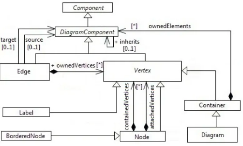
Fig. 3. Diagram Elements
The visual grammar is used to describe the structure of diagrams’ elements. This description is hierarchical: a root element can contain other elements. We propose two main types of elements: Vertices to represent complex elements of diagrams and edges to represent links between complex elements.
Vertex is node abstraction, it consists of main nodes (top nodes), sub-nodes (contained vertices in figure 3) and attached nodes (nodes that can be affixed to other nodes). A label is a vertex that allows access to nodes textual elements via their accessors (getters and setters). This will synchronize the data model with text value represented. A Bordered node is a node that can be affixed to other nodes. Containers (Compartments) are specific nodes that contain diagram elements. A Diagram is itself a container. An Edge is a connection between two diagram elements, this relationship could be specified seman-tically (in the domain metamodel) or graphically and could be more complex than a simple line (e.g. buses).
Edges and nodes have both the ability to inherit from each others. When a diagram component inherits from another, it recuperates all its structure, style and behavior. If the inheriting component declares an interface with the same name as the inherited component, this is interpreted by an overload and then we can override the structure, style and behavior. This feature maximizes components reuse and allows creating other derivatives components. Visual grammar elements only represent the structure and should be associated to a visual vocabulary describing its rendering.
B. Visual Vocabulary: Visual Variables
Visual vocabulary allows describing the graphical symbols (visual representation) of diagrams’ elements. This description is composed of different visual variables; we regroup all of them in the Style concept (fig. 4) representing the shape, color, size, layout...
All diagram components are associated via their style interfacesto visual vocabularies represented in the metamodel by the concept of Style. As other characteristics of diagrams el-ements, this relationship can be reused and overloaded through the proposed mechanism of inheritance.
The Vertex Styles are characterized by the layout attribute, which represent the different arrangement rules in the host
Fig. 4. Visual variables(Styles) description
figure. Vertex styles are decomposed into two main categories: node styles (NodeStyle) and label styles (LabelStyle). Node styles represent shapes (2D and 3D figures and iconic repre-sentations like images). We propose around ten default shapes in our metamodel, and we let users to create their own shapes with polygons, images and custom styles (code implementa-tion). The Edge Styles could be simple lines (LineStyle) or more complex shape (ComplexStyle).
IV. VALIDATION
To validate our proposal, we have developed a chain of transformations allowing the full generation of designed editors code. Note that MID metamodels are completely independents from technological targets. In the actual implementation, we choose GMF as technological target.
We illustrate the advantages of our approach on an example specifying the UML Classifier element to show the reusability through inheritance. Then, we validate our approach through a case study.
A. Reuse by Inheritance
We chose as an example the UML concept Classifier. This abstract concept is the basic element of several concepts (Class, Interface, Component...). We want to specify the graph-ical appearance of the item Classifier and use inheritance and overriding to specialize this specification.
Fig. 5. Reuse by Inheritance
The basic element of Classifier consists graphically of a label followed by a compartment that contains properties.
To specify a Component, we have simply to inherit from Classifier and add to its structure, a border node representing the component ports (attached on borders).
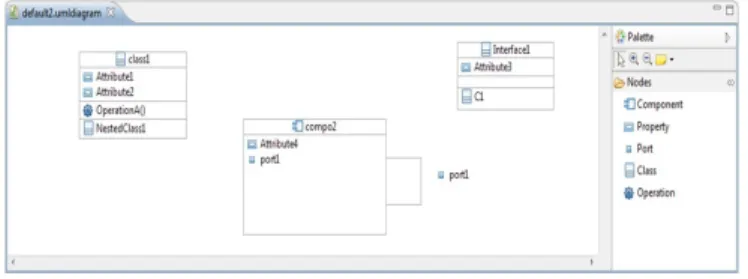
To Specify the graphical elements Class and Interface, we have simply to inherit from Classifier and add to its structure two other compartments, the first for operations and the other one for nested classifier. In this example, and to simplify, the Interface inherits from the graphical definition of the Class to show the graphical similarity between the two concepts. The figure 6 shows the generated result.
Fig. 6. Generated editor for this example
The example below shows the overriding of inherited ele-ments. The component ”Node B” inherits from the component ”Node A”. Both have sub-components named ”Node x”, in this case the element ”Node x” of B overrides the description of ”Node x” of A (initially represented by an ellipse).
Fig. 7. Example of graphical overriding
V. CONCLUSION
In this article, we present an approach based on MDE and components modeling, allowing the easy specification of diagram graphical editors at a high level of abstraction, in order to model, reuse, compose and generate code. In our proposal, we focus on the component concept, to describe and then assemble concepts emerging from visual languages. First, In MID, we solve some problems identified in existing tools and methods on the industry as in the literature. For example, the specification at a high level of abstraction without the need for manual programmatic intervention, the separation of concerns, the graphical effectiveness and finally editors reusability, which was among the major problematic of our research work. To validate our approach, we have developed a transformation chain targeting the GMF technology (GMFGen), which allows in turn generation of functional editor’s code. This allows us to successfully design diagrams by reusing existing compo-nents, and to generate their implementation We validated our approach on several diagrams.
Our approach presents many advantages. First, through the reuse of model: the models are theoretically more easily to understand and to manipulate by business users; which corresponds to a goal of the MDE. Secondly, this reuse saves considerable gain of productivity through ease of maintenance of components; it allows better teamwork and helps for the industrialization of software development: it is possible to build libraries of components, and then build the diagram by assembling these components.
Briefly, we can say that our approach opens a new way that shows promises for wider use of modeling tools and automatic generation of applications. Compared to the current development technologies, the promises of this approach are large through the ability to create complex applications by assembling existing simple model/components fragments, and especially the possibility for non-computer specialists, experts in their business domain, to create their own applications from a high-level description using an adapted formalism, easy to understand and manipulate for them.
In the current state of our research, many studies are still required to reach a full generation of modeling tools. First, we need to finalize the description and generation of all graphical editors of Papyrus with our approach. Finally, we need to define other metamodels that allow description of the other parts of such tools (Tree editors, tables/matrices, properties views...) following the same approach of component reuse and inheritance.
REFERENCES
[1] A. El-Kouhen, C. Dumoulin, S. Gerard, and P. Boulet, “Evaluation of modeling tools adaptation,” CNRS, Tech. Rep., 2011, http://hal. archives-ouvertes.fr/hal-00706701.
[2] S. Gerard, C. Dumoulin, P. Tessier, and B. Selic, “Papyrus: A uml2 tool for domain-specific language modeling,” in Model-Based Engineering of Embedded Real-Time Systems, ser. Lecture Notes in Computer Science, 2011. [Online]. Available: http://dx.doi.org/10. 1007/978-3-642-16277-0 19
[3] D. Moody, “The physics of notations: Toward a scientific basis for con-structing visual notations in software engineering,” IEEE Transactions on Software Engineering, 2009.
[4] ISO/IEC, “24744: Metamodel for development methodologies,” 2007. [5] W. S. Cleveland and R. McGill, “Graphical perception: Theory,
experimentation, and application to the development of graphical methods,” Journal of the American Statistical Association, vol. 79, no. 387, pp. pp. 531–554, 1984. [Online]. Available: http://www.jstor.org/ stable/2288400
[6] G. L. Lohse, “A cognitive model for understanding graphical percep-tion,” Hum.-Comput. Interact., vol. 8, no. 4, pp. 353–388, Dec. 1993. [Online]. Available: http://dx.doi.org/10.1207/s15327051hci0804 3 [7] W. Winn, “Learning from maps and diagrams,” Educational Psychology
Review, vol. 3, pp. 211–247, 1991. [Online]. Available: http: //dx.doi.org/10.1007/BF01320077
[8] J. Bertin, Semiology of graphics : diagrams, networks, maps. Univer-sity of Wisconsin Press, Madison, Wisconsin, 1983.
[9] P. Bottoni and A. Grau, “A suite of metamodels as a basis for a classification of visual languages,” in Visual Languages and Human Centric Computing, 2004 IEEE Symposium on, sept. 2004, pp. 83 –90. [10] A. Ledeczi, A. Bakay, M. Maroti, P. Volgyesi, G. Nordstrom, J. Sprin-kle, and G. Karsai, “Composing domain-specific design environments,” Computer, vol. 34, no. 11, pp. 44 –51, nov 2001.
[11] S. Kelly, K. Lyytinen, and M. Rossi, “Metaedit+ a fully configurable multi-user and multi-tool case and came environment,” in Advanced Information Systems Engineering, ser. Lecture Notes in Computer Science, P. Constantopoulos, J. Mylopoulos, and Y. Vassiliou, Eds., 1996.