HAL Id: hal-01286291
https://hal.archives-ouvertes.fr/hal-01286291
Submitted on 27 Sep 2018
HAL is a multi-disciplinary open access
archive for the deposit and dissemination of
sci-entific research documents, whether they are
pub-lished or not. The documents may come from
teaching and research institutions in France or
abroad, or from public or private research centers.
L’archive ouverte pluridisciplinaire HAL, est
destinée au dépôt et à la diffusion de documents
scientifiques de niveau recherche, publiés ou non,
émanant des établissements d’enseignement et de
recherche français ou étrangers, des laboratoires
publics ou privés.
Low overhead loop-free routing in wireless sensor
networks
H. J. Audeoud, M. Krol, Martin Heusse, Andrzej Duda
To cite this version:
H. J. Audeoud, M. Krol, Martin Heusse, Andrzej Duda. Low overhead loop-free routing in
wire-less sensor networks. 11th International Conference on Wirewire-less and Mobile Computing,
Network-ing and Communications (WiMob), Oct 2015, Abu Dhabi, United Arab Emirates.
pp.443-451,
Low Overhead Loop-Free Routing in Wireless
Sensor Networks
Henry-Joseph Audéoud, Michał Król, Martin Heusse, and Andrzej Duda
Grenoble Alps University, Grenoble Institute of Technology, CNRS Grenoble Informatics Laboratory,
38000 Grenoble, France. Email: {firstname.lastname}@imag.fr
Abstract—We consider the crucial problem of routing in wireless sensor networks. Routing protocols need to deal with topology changes while keeping the routing overhead low, especially the number of broadcasts, to save energy. In this paper, we consider the problem of building and adapting default routes for convergecast and host routes for downward traffic. We first propose a local repair scheme that allows arbitrarily long periods for rebuilding the tree/DODAG of default routes. Second, we design a scheme for preventing packet forwarding along routing loops, which may occur in the combination of broken host routes and default routes. We achieve this goal without adding an additional header to packets. The two schemes along with on-demand host route construction provides a complete routing solution that addresses many of the shortcomings of RPL. We validate the proposed schemes with Cooja emulations and an experimental evaluation on a real-world sensor network testbed.
I. INTRODUCTION
Routing in multi-hop wireless sensor networks is crucial for maintaining connectivity and, at the same time, it is a complex task because of specific characteristics of this type of networks. The quality of wireless links is highly variable, nodes may go down, new nodes may join the network, and nodes may change their location. So, the routing protocol needs to guarantee that if the topology is modified, the routing structure is properly adapted without creating loops. Moreover, it has to introduce minimal overhead and take into account the contraints of the available energy
In RPL, the Routing Protocol for Low-power and Lossy networks [1], each node selects a preferred parent to form a Collection Tree (CT) [2] rooted at the sensor network sink. Nodes also keep the information about several parent nodes to change when the current preferred parent is down, so RPL in fact builds a more complex routing structure— a DODAG (Destination Oriented Directed Acyclic Graph). The collection tree or DODAG supports MP2P—multipoint-to-point or convergecast traffic pattern with a default route to the sink going through the preferred parent node. In addition to convergecast, nodes also need to support downward traffic from the sink to all or some sensor nodes, e.g. typical CoAP application traffic generates packets to query sensor nodes. RPL proactively creates host routes in the network
for downward traffic by installing an entry in the routing table for each node. Nevertheless, RPL has no mechanism to rebuild a route toward a specific node, other than having all nodes in the network resend a packet to declare themselves, thus at a high cost in terms of packet transmissions. The routing structure also supports P2P traffic between any pair of nodes. Packets that go from a sensor to another one may either follow the default route up towards the sink and then down to the destination, or, alternatively, the routing protocol can create and maintain direct host routes.
A particular property of RPL is that it needs to add a specific data structure to every forwarded IP packet, which increases the overhead of each packet transmission. Such addition of information to each packet header is seldom required in Internet protocols and often results in adding an additional IPv6 header, which makes things even worse. LOADng is another Lightweight On-Demand Ad-Hoc Distance vector routing protocol [3] dedicated to wireless sensor networks. LOADng considers a network as flat and not organized in a tree or DODAG structure. It creates all routes reactively only when needed. A topology change remains unnoticed unless it impacts a currently active route. The LOADng messages are minimal with little overhead, nevertheless; LOADng may spend much energy on finding routes.
LRP, the Lightweight Routing Protocol [4], [5] combines the collection tree or DODAG topology of RPL and the reactive route establishment of LOADng. We adopt LRP as the base for further enhancements proposed in this paper. In particular, we consider the problem of building and adapting default routes for convergecast and host routes for downward traffic. We first propose a local repair scheme that allows arbitrarily long periods for rebuilding the tree/DODAG of default routes. Second, we design a scheme for preventing packet forwarding along routing loops, which can always happen in the combinations of broken host routes the tree/DODAG of default routes. We achieve this goal without adding an additional header to packets.
We start with the description of the protocol for DODAG creation (Section II) and repair (Section III). Then, we consider the route validation mechanism to guarantee that
LRP is loop free (Section IV). We describe simulation tests to demonstrate the validity of the proposed schemes (Section VI). Finally, Section VII briefly describes the related work and Section VIII concludes the paper.
II. BACKGROUND ONROUTINGPRINCIPLES
We start with a brief recall on the principles of the DODAG construction in RPL and the mechanisms brought by LRP.
A. DODAG Construction—Default Routes
In RPL and LRP, nodes construct a DODAG structure of default routes for convergecast traffic from nodes to the sink. The protocols use distributed Bellman-Ford algorithm based on the propagation DODAG Information Object (DIO) messages in the whole network. A node advertises a route to the DODAG root (the sink or the edge router) by broadcasting a DIO to the nodes in its vicinity1.
We call successors of a node all nodes that provide it with a route to the root. Predecessors of a node are all nodes to which it provides a route to the root.
A node has to compare routes received in a DIO message. A route comes with three information elements:
• DODAG identifier: the IP address of the DODAG root that allows identification of the DODAG to which belongs a given route. It is not modified by nodes other than the root. A node must learn it from its successors through a DIO message.
• DODAG sequence number: set by the root that in-crements it to recreate the DODAG from scratch— this operation is called a global repair. If the DODAG identifiers differ, the sequence number is not taken into account.
• metric: provides the cost of the route to the root in the form (type, value). If the types differ, the metric is not taken into account. The metric broadcast by a node must be strictly greater than all the metrics broadcast by its successors.
The information allows defining a partial order of the received routes. The sequence number takes precedence over the metric: the best path is the one with the greatest DODAG sequence number and, if equal, the smallest metric.
To avoid loops, nodes must always obey the following rule2: a node must not move away from the root. A node must not select a given node as its successor if this selection would offer a route worse than the previously offered one.
If the DODAG identifiers differ in two routes, a node may prefer one DODAG to another or it may compare the metrics. The choice depends on use cases. The use of metric
1For remarks on broadcasting, see Section V-B. 2Always means even if a node restarts (cf. Section V-A).
types also depends on use cases. The metric type can for example be the hop count, the Expected Transmission Count (ETX), or the Received Signal Strength Indication (RSSI).
The LRP protocol uses sequence numbers as in LOADng [3]: First, the root maintains the DODAG se-quence number. It increments in case of a global repair, similarly to RPL. Secondly the node sequence numbers increment upon the creation of RREP, RREQ, or BRK message. If a node only forwards such a message, it does not modify the sequence number.
Nodes periodically broadcast DIO messages to take into account potential topology modifications. As the interval between two consecutive DIOs may be long (RPL expo-nentially increases the interval with trickle), a node can probe its neighborhood by sending a DODAG Information Solicitation (DIS) message [1]. DIS solicits a transmission of a DIO from neighbor nodes. All receiving nodes reply with a unicast DIO message. DIS messages decrease the time for joining the network.
B. Downward Traffic—Host Routes
The downward traffic is also called point-to-multipoint traffic. It goes from the border router (the sink) to any node inside the network. This kind of traffic needs the establishment of host routes at nodes. We can establish host routes in a reactive way, on demand when they are needed, using the same approach as LOADng [3], but we can optimize the search process to establish host routes by taking advantage of the existing DODAG routing structure to efficiently flood route requests in the network. We can also build host routes in a proactive way like in RPL, depending on use cases.
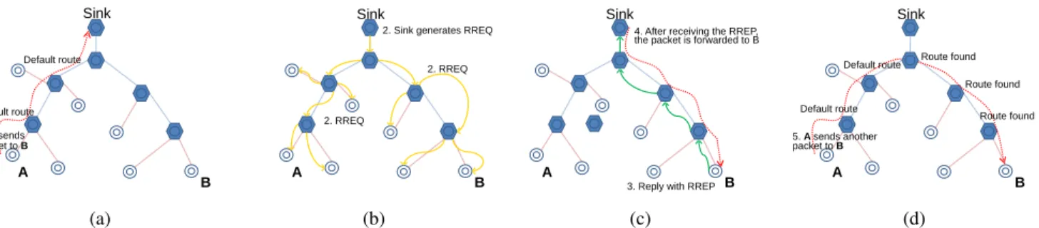
Figure 1 presents the principles of the establishement of host routes [5]. We explain them below with more details.
1) Route Requests: The root searches for downward routes by flooding3 a RREQ message (Route Request) in the network. The root uses its internal sequence number and its address to fill the RREQ message (not the DODAG sequence number, which is used to create and maintain the DODAG itself). There is no need to track the origin of RREQ messages (the LOADng “reverse route”), because the sender is always the root.
2) Route Replies: When a node receives a RREQ mes-sage destined to one of its addresses, it replies by sending a RREP message (Route Reply). The internal sequence number of the node is used to fill the RREP sequence number. The source address holds the address requested in the RREQ message and the destination address is the address of the root. The metric value is initialized to 0.
A RREP message must not be send or forwarded to a node not used as a successor. When forwarding a RREP message, a node creates a host route in its routing table (like the LOADng “forward route”). The destination of this route
A B Sink 1. A sends packet to B Default route Default route (a) A B 2. RREQ 2. RREQ
2. Sink generates RREQ
Sink
(b)
A
B
3. Reply with RREP 4. After receiving the RREP, the packet is forwarded to B
Sink (c) A B 5. A sends another packet to B Default route
Default route Route found Route found
Route found
Sink
(d)
Figure 1: Routing scheme: (a) Packet sent to node B takes the default route up to the Sink; (b) Sink generates a RREQ packet flooded throughout the network; (c) Node B replies with RREP and the packet goes over the created route; (d) Any other packet follows the shortest route. [5]
is the source address of the RREP message. The next hop used for this route is the neighbor from which the RREP has been received. A RREP message deprecates all routes with the same source address and a smaller sequence number.
3) Spontaneous Route Replies: A node may sponta-neously send a RREP to any of its successors. In this case, the destination address must be either the root or the link-local IP address of the successor. Sending a RREP message to its successor allows a node to be accepted by the datapath validation mechanism (cf. Section IV). When receiving a RREP message intended for its link-local IP address, a node must store the described route, but it does not forward the message.
C. Point-to-Point Traffic
A LRP network supports point-to-point traffic without any specific mechanism besides the described operation for upward and downward traffic. Nodes use the default route until the packet reaches a host route to the destination. If no host route exists for the destination, the packet goes upward to the root that generates a RREQ message to find the host route.
III. ROUTINGENHANCEMENT: LOOP-FREEDODAG REPAIR
LRP creates a DODAG structure based on default routes for convergecast upward traffic and takes advantage of the structure to efficiently establish host routes. In this section, we describe the main contribution of the paper: the DODAG repair that guarantees the absence of loops.
A. DODAG Repair
As the network topology may change, we propose two schemes to repair a DODAG.
1) Global Repair: LRP provides a global repair mecha-nism that can only be initiated by the root. The mechamecha-nism entirely recreates the DODAG. To initiate the global repair, the root increases the DODAG sequence number and broad-casts a DIO. The new sequence number will propagate to all
the nodes in the network that renew the choice of the best routes in the new DODAG.
Initiating a global repair may not be an optimal solution in many circumstances. First, a global repair may imply increased energy consumption by requiring a new network-wide broadcast. Second, it may disturb a portion of the network that was already operational and optimal. Third, it cannot be initiated by any node, but only by the root.
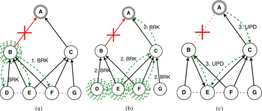
2) Local Repair: The local repair mechanism, or Link Reversal mechanism (LR) provides a solution that does not involve all the nodes in the network and it can be initiated by any node. A node should perform a local repair (later called the detached node) when it cannot re-associate itself with the DODAG (we call the node a detached node in this case), because all its successors are unreachable and all remaining neighbor nodes cannot be chosen as successors without moving away from the sink (the rule for loop free routes). The LR mechanism tries to reverse some links between the detached node and its predecessors to use them as successors without creating loops in the DODAG.
The detached node creates and broadcasts a BRK mes-sage containing the detached node address and its internal sequence number (cf. Figure 2a). Nodes process BRK in the following way (cf. Figure 2b):
• If BRK comes from a successor, the node is in the detached sub-DODAG so it has to rebroadcast BRK. • If BRK does not come from a successor, the mes-sage is compared to the content of a cache: if it already contains a message from the detached node with a route better than the one in BRK, the BRK message is dropped (the comparison of routes takes into account DODAG identifier and sequence number as well as metrics as described above). Otherwise, the BRK came from a successor, the node increments the metric in BRK according to the link cost between the node and the previous sender of BRK. Then, the node forwards BRK to its successor (thus, on the shortest route to the root). The node stores the address of the BRK sender.
(a) (b) (c)
Figure 2: Example of a DODAG local repair when the link A-B breaks. (a) After the link break, B broadcasts a BRK message. (b) BRK message is forwarded to the root. (c) The root answers with an UPD message. The links between B and {E,F} are reversed.
It may happen that a node receives BRK from a node that is not its successor, although it is in the sub-DODAG of the detached node. It is not an issue, as its successors have cached the BRK message and will not forward it further. However, if it subsequently receives a BRK from a successor, it must broadcast and store it in the cache even if it already transmitted it to its successors.
When the root receives BRK, it replies with a UPD message forwarded on the route stored by the passage of BRK messages in the opposite direction until it reaches the detached node. UPD has the same role as DIO: transmit the DODAG sequence number and the metric to the nodes in the network, but UPD is addressed to a specific node and not to all nodes as DIO (DIO is a broadcast and UPD is a unicast). The UPD message carries the new DODAG sequence number and it overrides the route information used in the route cost computation from the previously received DIO messages. However, nodes use the information received in the last DIO message when broadcasting a DIO message and not the information received in the UPD message, which avoids disturbing the nodes not involved in the repair with the new sequence number.
As the UPD message contains a higher repair sequence number than any sequence number sent before, all receiving nodes will accept the sending node as their successor, which does not create loops in the DODAG. Indeed, at the moment a node re-sends the UPD, it has already updated its position in the DODAG with the new sequence number, so it does not use the receiving nodes as successors anymore.
We can see in Figure 2c that the link between nodes B and E is reversed: at the beginning, B was a successor of E and in the end, E is a successor of B. The operation is well founded: B cannot provide access to the DODAG root to E any more, so it needs to use it to reach the root.
This operation limits the number of changes in the net-work but does not rebuild a shortest path tree: for instance, D keeps B as its default route next hop. The benefits of this
method is that the flooding is limited to the detached subtree and only unicast packets flow in the rest of the network. Other protocols use this kind of unicast round trip to the sought destination to rebuild a lost route: TPGF [6] uses one packet to walk through the detached sub-tree until it finds a way out and comes back. In Babel [7], sequence number request may travel all the way to the target and trigger an update.
IV. DATAPATHVALIDATION
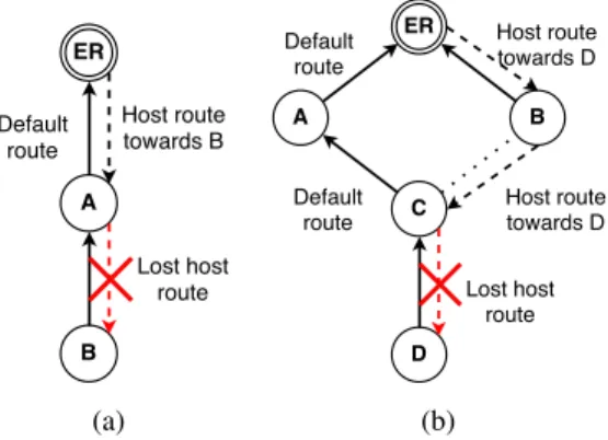
In a LRP network, host and default routes coexist. When the routing tables are not consistent, this coexistence may create a routing loop. Figure 3 gives examples of routing loops:
• Figure 3a presents the simplest example: we assume that node A has lost the route to node B. Any packet destined to B coming from the edge router ER (the root) is in the loop between ER and A.
• Figure 3b gives another example in which more than two nodes are involved. We assume that node C has recently changed its successor from B to A. The route from ER to D through B and C is active. If node C looses its route to D, a loop is created for this destination between ER, B, C, and A.
As it is difficult to keep a distributed system consistent, we will not try to keep the LRP network consistent, but rather, thanks to its reactive operation, we will guarantee that an inconsistent situation is detected and is repaired before causing problems.
A. Loop Detection
Let x be a route entry matching a given destination at a node. x contains the destination (a prefix and its length, plen), the next hop, the sequence number (seq), and a metric (m). Then, we can define an order ≺ on any two
(a) (b)
Figure 3: Examples of routing loops. route entries x and y in the network:
x ≺ y ⇔ x.plen > y.plen ∨
x.plen = y.plen ∧ (x.seq > y.seq ∨ x.seq = y.seq ∧ x.m < y.m)
In a nutshell, x ≺ y if x is more specific, newer, or shorter than y, in this order of priority.
Using the order, we enforce that packets do not loop in the network as long as the routing entries that packets match along their route are strictly decreasing. Thus, the routing entries create a gradient on the nodes leading to the destination node. One of the difficulties is to make sure that packets never “use” a default route after matching a host route at some node.
B y A x
Figure 4: Using routing entry x at A to route a packet coming from B that followed entry y
We consider the case of a packet matching a routing table entry x at node A, coming from node B where it was forwarded according to routing entry y (see Figure 4). We denote by xd, yd, the default routes at A and B.
a) When matching a host route at A:
• If the packet comes from a predecessor node, it was forwarded using a default route, which is a more general routing table entry, so x ≺ yd (this
is the point at which the packet is now going down towards the destination after going up the tree). • Otherwise, if B is closer to the sink (xd yd),
the packet is following a host route. If B points to A for this destination, it means that A sent a RREP to B in the past and thus, x ≺ y. Even if, in the meantime, A got another RREP that was not (yet) sent to B, the new routing table entry in A x+ verifies x+≺ x ≺ y.
b) When matching the default route at A:
• It is the responsibility of B to send packets to successor node A only using the default route entry. So, when B selected A as successor, we impose that B had to remove all host routes in which A is a next hop (Rule 1).
• When A uses route xd, it needs to check that the
previous hop is effectively a predecessor. So, A verifies that it has received a RREP from B in the past (Rule 2), which guarantees that then xd≺ yd.
If B subsequently moves closer to the sink, it will send packets to A only if it gets a RREP from A, so A is not using any more its default route. In general, for a destination outside of the sensor network, only default routes will match, there is no need for any additional check.
B. Predecessor Advertisement
When a node restarts, we impose that it keeps track of its own sequence number all the time to be able to override previous RREPs. Not complying to this principle only puts a node at risk to be unreachable until it catches up its former sequence number.
Another requirement—to keep track of the metric, the sink address, and the associated sequence number is also important: if a node reboots and re-attaches to one of its (indirect) predecessors, a loop is created, and the conditions in the section above are not sufficient to keep the packets from looping around.
To do away with this requirement, we require that nodes check the sequence number of the sender when receiving packets from an unknown node: if A re-attaches further down after a reboot and gets a packet from B (that uses a route dating from an instant before A restarted), this predecessor is unknown. It will send a DVE (Datapath Validation Error) message to B. The DVE contains the default routing entry of A (sequence number, sink, metric) so B can compare it with its local entry, and detach from A in this case.
Conversely, if everything is in order, B advertises itself as a predecessor to A with a DVA (Datapath Validation Ad-vertisement) message. This message may be sent proactively after selecting a successor (i.e. parent) to avoid the DVE— DVA handshake.
C. Routing Loop Erasure
When a node (say node A) detects a loop, it has to erase it. A sends back a DVE message to the neighbor from which the looping packet came from (say node B). There are two cases:
• Either B receives the DVE from its successor (de-picted in Figure 5a), which means that A does not
(a) (b)
Figure 5: Sending DVE after the detection of a routing loop. (a) Node B is not known as a predecessor by node A, B identifies itself with a DVA message. (b) Node B used an obsolete host route, no more known by A, so the route is erased.
know that B is its predecessor. B must answer with a DVA message.
• Or B receives the DVE from another node (depicted in Figure 5b) which means that B used an obsolete host route that A removed. The route must be deleted and not be used again. B deletes this host route and forwards the RERR message to its own successor to avoid using this host route anymore. The RERR message will be forwarded from one node to its successor to delete the host route.
V. IMPLEMENTATIONNOTES
A. Writing Informations on Non-Volatile Memory
To ensure network consistency, some information must not be lost by a node: first, its current position is the DODAG (the sink address DODAG, the DODAG sequence number, and the current distance to the sink), and second, the internal sequence number of the node. The information must not be lost if a node reboots, so we consider storing it in a non-volatile memory.
B. Flood and Broadcast Operation
LRP needs to broadcast (at the link-local scope) and flood (to all nodes in the network) some messages, but it does not define a specific method to perform these opera-tions. The best method to use depends on a given medium access layer, which is let to the implementation.
Flooding a message does not mean that all nodes should send the message, but rather that all nodes must receive the message. The DIO, RREQ, and BRK messages are retransmitted by neighbors, which may generate collisions. The broadcast operation must pay attention to collisions if the MAC layer does not provide mechanisms to mitigate their impact.
Some nodes may be configured not to forward the packets of other nodes, which may be useful if a node has little residual energy. In this case, they do not have to broadcast DIO, RREQ, and BRK messages. Nevertheless,
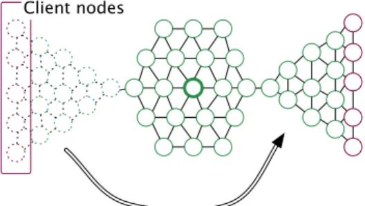
Client nodes
Figure 6: Placement of the nodes during the simulation. A whole subtree moves to a different location after 100s, breaking the routes to and from the clients.
the node must be able to send RREP messages and reply to RREQ and RERR messages.
C. Neighbor Unreachability Detection
The local repair scheme described in Section III starts when the last successor is declared unreachable. LRP does not define a specific method to perform a Neighbor Un-reachability Detection (NUD). If the medium access layer is not able to detect unreachability of a neighbor, the implementation must provide a way to detect it (e.g., by implementing the IPv6 NUD algorithm). The reaction time of the NUD algorithm must be small compared to the global repair frequency (described in Section III-A1).
VI. EXPERIMENTATIONS
To validate LRP, we have implemented it on Contiki OS [8]. To compare LRP with RPL, we have used the ContikiRPL implementation [9] provided with Contiki. We have used the Cooja emulation tool [10] to validate the protocol functionalities. We have also run LRP on real motes on the IoT-lab testbed [11]. We present below the results of experimentations.
A. Emulation in Cooja
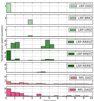
We compare the routing packet emission rates between RPL and LRP in a 10 minutes long emulation in Cooja. Figure 6 presents the placement of nodes: 35 nodes are arbitrarily placed around the sink and start to operate at t = 0. Some client nodes, placed on a subtree structure, send traffic to the sink (upward traffic) that replies by sending back another packet (downward traffic). After 1’40s, the subtree with the client nodes moves from one place to another, which generates a link break. Figure 7 shows the packet emissions during this emulation.
At the beginning, LRP nodes build a DODAG with DIO messages and they proactively establish host routes by transmitting RREP messages. 30 seconds after, the first packets are transmitted. Some of them trigger a reactive host route establishment through RREQ and RREP messages. Indeed, some host routes have not been completely built,
1 LRP-DIO
1 LRP-BRK
1 LRP-UPD
2 4
Packet emission speed (packets/s)
LRP-RREQ 2 4 LRP-RREP 2 4 LRP-RERR 2 4 RPL-DIO 0 1 2 3 4 5 6 7 8 9 10 Time (min) 2 4 RPL-DAO
Figure 7: Comparison between the rates of routing packets generated by RPL and LRP in the scenario of Figure 6. 6 graphs at the top correspond to LRP messages, 2 graphs at the bottom to RPL messages. The comparison shows that LRP is quiet most of the time, contrary to RPL. A local repair takes place around the third minute. (Note that scales are not the same between upper 3 and lower 5 graphs).
because of collisions of RREP messages (all nodes start at the same time).
RPL uses the trickle algorithm [12] to broadcast DIO messages. According to the algorithm, messages are trans-mitted all the time, more frequently at the start and then with more and more delay between repetitions. DAO messages are broadcast at the beginning to establish host routes for downward traffic. They are also emitted continuously to maintain routes, because the sink has no method to solicit the creation of host routes.
Comparing RPL and LRP, it is plain that LRP is much more “quiet” than RPL. RPL needs to constantly broadcast DIO and DAO messages, while LRP benefit from the local repair (no need for constant DIO emissions) and from reactive host route establishment (no need for constant RREP/DAO emissions) mechanisms. RPL is always active contrary to LRP that is only active when maintenance is needed.
We can also observe the local repair done by LRP that occurs because of the subtree movement at time 1’40s. The link break is only detected at 3’ by the Neighbor Unreachability Detection algorithm (NUD). At this time, the nodes send BRK and UPD messages according to the local repair mechanism. However, just after 3’, host routes are not yet repaired, because the used NUD algorithm is only active when there is some traffic on the link. Hence, we have to wait until 4’ to obtain the situation in which the
10
50
Broadcasted packets
DIO Broadcast
10
50
BRK Broadcast
10
50
RREQ
10
50
Packet emission speed (packets/s)
DIS
10
50
Unicasted packets
DIO Unicast
10
50
BRK Unicast
10
50
UPD
0 5 10 15 20 25 30 35 40 45 50 55 Time (min)10
50
RREP
Figure 8: LRP on IoT-lab — Number of routing packets generated per time slices of 30s. A global repair takes place after 30mn.
obsolete host routes are deleted thanks to RERR messages, and rebuild reactively thanks to RREQ and RREP messages. The effect of the subtree displacement is not visible under RPL, because of the constant emission of DIO and DAO messages that automatically repair the default and host routes.
B. Experimentation on IoT-lab
To validate the performance of the proposed schemes in real world conditions, we have run experiments on M3 nodes [13] of the IoT-lab testbed, using 1 server and 34 clients, all placed in a 3D grid. The server is also the sink and it replies to packets sent by each client every 15s. The traffic of routing messages appears in Figure 8. We use the hop count metric, which, in fact, gives surprisingly satisfactory results and causes much less overhead then ETX at the start. This experiment illustrates well several aspects of the behavior of LRP. First, nodes re-broadcast only once after a DIO reception that “improves” the node position, whereas RPL would keep on sending indefinitely, following the trickle algorithm. So, we witness no background DIO traffic, whereas DIS are of utter importance, since it is only the un-associated nodes that actively probe. Here, DIS packets appear regularly, they correspond to one node that is out of range of the rest of the network. Unicast DIOs follow
the reception of DIS messages. Second, after approximately 11mn (and also after 36mn), a node looses its next hop and broadcasts a BRK (after attempting to repair by sending a couple of DIS). This broadcast is followed by unicast BRKs that reach the sink. It triggers the transmission of UPD packets after which, the tree is repaired. Third, spontaneous RREP are transmitted upon attachment to a new successor, so there are few RREQ transmissions.
Finally, at t = 30mn, a scheduled global repair takes place, and DIOs flood the network. Here, LRP does not use any mechanism to reduce flooding overhead (such as trickle), DIS and DIO broadcasts are simply (re)transmitted with a random delay to avoid collisions. This period of 30mn is purely for illustration purposes and it could be much larger depending on the use case.
It is interesting to take a closer look at the reason why BRK packets appear in this experiment. It happens, once per global repair in this case, that node N receives a DIO from successor S that advertises a good metric, although it is not effectively usable, due to a high loss probability, for instance. Then, N will eventually discard S, but it needs to move further down the tree to reconnect. A local repair allows this move with minimal overhead. In RPL, this problem may be solved by using, for instance, the ETX metric initialized at a high value, although this leads to prefer well-known next-hop nodes compared to untested alternative neighbors. Also, using a non-zero DAGMaxRankIncrease authorizes a limited movement away from the sink, although at the cost of transient loops. The point here is that a quick low overhead local repair mechanism changes the criteria for the choice of a metric.
VII. RELATEDWORK
The MANET community has focused more on building and maintaining host routes in a flat network than injecting prefixes, although OLSR [14] allows to publish HNAs (Host and Network Associations). The tacit hypothesis is that host routes and prefixes are disjoint.
The Babel routing protocol [7] considers the case of routing loops due to the default route subsuming a route to a host that has vanished. In Babel, the idea is to mark unreachable and maintain the old route long enough for the stale routing entries to expire. This approach imposes to keep track of past routing events, which increases the amount of information nodes have to keep in persistent memory banks. Moreover, reducing routing traffic leads to using relatively long route timeouts, which makes matters worse. Finally, as we consider a network in which the routing information is localized to the path above each destination, if a sensor changes location, it does not necessarily update its former predecessors; so it becomes unreachable from them.
The Temporally-Ordered Routing Algorithm (TORA) [15] has a route maintenance mechanism, which can repair a link failure. Nodes are organized in a directed acyclic graph oriented to a destination. The
idea is to detect when a node has no more routes to a destination—it is a dead end for this destination. To solve this problem, the node must use the nodes belonging to its subtree. The routes that leads to this dead end must be reverted, until another valid route is found. This approach needs synchronization between two nodes, as they must both revert a route. A packet loss leads to a de-synchronization and results in routing loops, which may be a problem in wireless sensor networks with high loss rates.
A. RPL Datapath Validation
In RPL [1], routing loops are not possible because every data packet bears a RPL option header containing the direction of the packet (bit O) and the rank of the sender. In this way, every packet sent contributes to checking the topology—this mechanism is inherited (like trickle) from the Collection Tree Protocol (CTP) [2]. Unfortunately, this property comes at a rather high price: for the packets originated from outside of the sensor network or for the packets destined to outside, it becomes mandatory to tunnel them so to add an outer IPv6 header. In this way, in case a routing problem is detected for inward traffic, the ER gets the ICMP notification. Strong packet header compression is mandatory to regain a satisfactory efficiency with such over-head. Interestingly, the piggybacking of routing information on each packet was never questioned during the elaboration of RPL.
VIII. CONCLUSION
LRP is a routing protocol dedicated to wireless sensor networks. It is based on a DODAG structure that allows it to easily forward upward traffic to the sink. The DODAG structure can efficiently adapt itself to a changing topology, thanks to a local repair algorithm and a reactive route establishment. LRP is loop free guaranteed by the datapath validation algorithm that allows the protocol to check the distributed routing information consistency while routing data packets.
We have validated the proposed schemes with Cooja emulations and an experimental evaluation on a real-world sensor network testbed. The preliminary results show that LRP has less overhead than RPL, thanks to the local repair mechanism.
The perspectives are numerous:
• The utility of the local repair must be considered. Indeed, it depends on the density of the network, the propagation method, and the mobility of the nodes. For example, in a high-density network, a local repair may generate significant traffic with little benefits. Thus, we need to find an optimal trade-off between the reliability and the traffic overhead generated by the repair.
• There are numerous metrics: hop count, RSSI, ETX or many other metric may be used. However, some
of them are more suitable than the others, depending on the network and on the parameters that have to be optimized.
• Flooding operation may also be optimized. For example, the BRK and RREQ messages can be processed thanks to a expanding ring search. De-pending on the situation, a connected dominating set or a Layer 2 forwarding schemes [16] can also be used to minimize the number of broadcasts needed to flood the whole network. Also, other flooding algorithms may be considered such as trickle [12] or multipoint relays [17].
ACKNOWLEDGMENT
This work was partially supported by the French National Research Agency (ANR) project IRIS under contract ANR-11-INFR-016 and by the LabEx PERSYVAL-Lab (ANR-11-LABX-0025-01) .
REFERENCES
[1] T. Winter, P. Thubert, A. Brandt, J. Hui, R. Kelsey, P. Levis, K. Pister, R. Struik, J. Vasseur, and R. Alexander, “RPL: IPv6 Routing Protocol for Low-Power and Lossy Networks,” RFC 6550 (Proposed Standard), Mar. 2012.
[2] Omprakash Gnawali, Rodrigo Fonseca, Kyle Jamieson, David Moss, and Philip Levis, “Collection tree protocol,” in Proceedings of the 7th ACM Conference on Embedded Networked Sensor Systems. ACM, 2009, pp. 1–14.
[3] T. Clausen, A. Colin de Verdiere, J. Yi, A. Niktash, Y. Igarashi, H. Satoh, U. Herberg, C. Lavenu, T. Lys, and J. Dean, “The Lightweight On-demand Ad hoc Distance-vector Routing Protocol - Next Generation (LOADng),” Work in Progress draft-clausen-lln-loadng-12, IETF, October 2014.
[4] Chi-Anh La, Martin Heusse, and Andrzej Duda Grenoble, “Link reversal and reactive routing in low power and lossy networks,” in Personal Indoor and Mobile Radio Communications (PIMRC), 2013 IEEE 24th International Symposium on. IEEE, 2013, pp. 3386–3390.
[5] Liviu-Octavian Varga, Gabriele Romaniello, Mališa Vuˇcini´c, Michel Favre, Andrei Banciu, Roberto Guizzetti, Christophe Planat, Pascal Urard, Martin Heusse, Franck Rousseau, Olivier Alphand, Étienne Dublé, and Andrzej Duda, “GreenNet: an Energy Harvesting IP-enabled Wireless Sensor Network,” IEEE Internet of Things Journal, 2015.
[6] Lei Shu, Yan Zhang, LaurenceT. Yang, Yu Wang, Manfred Hauswirth, and Naixue Xiong, “Tpgf: geographic routing in wireless multimedia sensor networks,” Telecommunication Systems, vol. 44, no. 1-2, pp. 79–95, 2010.
[7] J Chroboczek, “The Babel Routing Protocol,” RFC 6126, IETF, April 2011.
[8] A. Dunkels, B. Gronvall, and T. Voigt, “Contiki - a Lightweight and Flexible Operating System for Tiny Networked Sensors,” in Proc. of IEEE LCN, nov. 2004.
[9] Nicolas Tsiftes, Joakim Eriksson, and Adam Dunkels, “Low-power wireless ipv6 routing with contikirpl,” in Proceedings of the 9th ACM/IEEE International Conference on Information Processing in Sensor Networks. ACM, 2010, pp. 406–407.
[10] F. Osterlind, A. Dunkels, J. Eriksson, N. Finne, and T. Voigt, “Cross-level sensor network simulation with COOJA,” in Local Computer Networks, Proceedings 2006 31st IEEE Conference on, nov. 2006, pp. 641 –648.
[11] Eric Fleury, Nathalie Mitton, Thomas Noel, Cédric Adjih, Valeria Loscri, Anna Maria Vegni, Riccardo Petrolo, Valeria Loscri, Nathalie Mitton, Gianluca Aloi, et al., “FIT IoT-LAB: The largest iot open experimental testbed,” ERCIM News, , no. 101, pp. 14, 2015. [12] Philip Levis, T Clausen, J Hui, O Gnawali, and J Ko, “The trickle
algorithm,” RFC 6206, Mar. 2011.
[13] M3 Open Node motes, ,” https://www.iot-lab.info/hardware/m3/. [14] T. Clausen and P. Jacquet, “Optimized Link State Routing Protocol
(OLSR),” RFC 3626, IETF, October 2003.
[15] V. Park and S Corson, “Temporally-Ordered Routing Algorithm (TORA) Version 1 Functional Specification,” Work in Progress draft-ietf-manet-tora-spec-04, IETF, July 2001.
[16] Chi-Anh La, Liviu-Octavian Varga, Martin Heusse, and Andrzej Duda, “Energy-efficient multi-hop broadcasting in low power and lossy networks,” in Proceedings of the 17th ACM International Conference on Modeling, Analysis and Simulation of Wireless and Mobile Systems, New York, NY, USA, 2014, MSWiM ’14, pp. 41– 50, ACM.
[17] T. Clausen and U. Herberg, “Comparative study of RPL-enabled optimized broadcast in wireless sensor networks,” in Intelligent Sensors, Sensor Networks and Information Processing (ISSNIP), 2010 Sixth International Conference on, Dec 2010, pp. 7–12.