Controlled Manipulation Using Autonomous
Aerial Systems
by
Manohar B. Srikanth
M.Sc.(Engg.), Computer Systems, Indian Institute of Science (2007)
B.E., Electronics & Communication, University of Mysore (2001)
Submitted to the Department of Mechanical Engineering in Partial Fulfillment of the Requirements for the Degree of
Doctor of Philosophy
at the
MASSACHUSETTS INSTITUTE OF TECHNOLOGY
AcNES
% A SINSTTUTE
APR
S1
3
L BRA R iE S
February 2013
@
2012 Massachusetts Institute of Technology. All rights reserved
A u th o r: ...---
... - - ...
---Departmen of Mechanical Engineering
November 15, 2012
Certified by : ... - - - ...---- ---...---,-
---...---Anuradha M. Annaswamy
Senior Research Scientist, Department of Mechanical Engineering
Thesis Supervisor
A cce pte d by :...
David E. Hardt
Chairman, Department Committee on Graduate Students
Controlled Manipulation Using Autonomous Aerial Systems
by
Manohar B. Srikanth November 15, 2012
Submitted to the Department of Mechanical Engineering
The main focus of the thesis is to design and control Autonomous Aerial Systems, also referred to as Unmanned Aerial Vehicles (UAVs). UAVs are able to hover and navigate in space using the thrust forces generated by the propellers. One of the simplest such vehicles that is widely used is a Quadrotor. While UAVs have been predominantly used for "fly and sense" applications, very few investigations have focused on using them to perform manipulation by contact. The latter is challenging because of the dual goal of performing manipulation and maintaining stable flight. Because Quadrotors can quickly reach a location, their ability to manipulate can be impactful in many scenarios. While efficient flight control of Quadrotor has been an active research area, using Quadrotor to perform manipulation is novel and challenging. In this thesis, a range of Quadrotor designs and control strategies are proposed in order to carry out autonomous manipulation of objects.
We first derive a dynamic model of the Quadrotor that accounts for the presence of contact, object dynamics and kinematics. To improve manipulation performance, a passive light-weight end-effector interface between the Quadrotor and the object is proposed. The complexity of the dynamics is systematically reduced by making certain assumptions. The resulting dynamic model is divided into nonlinear subsystems on the basis of their degrees of freedom, for each of which separate controllers are designed. An efficient docking approach is proposed that permits fast and aggressive docking, even at very high speeds. Because a single Quadrotor UAS is limited in manipulation capability, a multi Quadrotor cooperative manipulation scheme is proposed.
Control strategies are proposed to deal with kinematic and parametric uncertainties. A manipulation scheme to open a door with unknown hinge location is proposed. A nonlinear adaptive controller is
implemented to perform efficient tracking in the presence of parametric uncertainty.
In order to improve robustness to accidental contacts, a novel flexible Quadrotor, denoted as ParaFlex, is designed. The advantages of ParaFlex over a rigid Quadrotor are demonstrated. A Simulation, Test and Validation Environment (STeVE) is developed to facilitate smooth and efficient transition from design
process to simulation to experiments.
Thesis Supervisor & Committee Chair:
A. M. Annaswamy, Senior Research Scientist, Department of Mechanical Engineering, MIT. Thesis Committee:
Prof. Jean-Jacques Slotine, Professor, Department of Mechanical Engineering, MIT Prof. Kamal Youcef-Toumi, Professor, Department of Mechanical Engineering, MIT Prof. Nicolas Roy, Associate Professor, Department of Aeronautics and Astronautics, MIT Dr. Eugene Lavretsky, Senior Technical Fellow, Boeing Research and Technology, CA.
Acknowledgments
First and foremost, I would like to express my deep and heartfelt gratitude to my research advisor Dr. Anuradha M. Annaswamy, who has been an incredible source of support, knowledge, and inspiration throughout the course of my stay at MIT. Right from the beginning, Dr. Annaswamy encouraged novel ideas, even if they deviated from the main stream of work in the laboratory. As openly as she accepted these proposed ideas, she critically forged them to ensure that they really qualified to be challenging, and important. Given that I come from a non-controls background, it was through her able guidance, that I could quickly put myself on the tracks of controls, and at the same time, was able to use my previous skill-set. I consider myself lucky to have her as my Ph.D. mentor, and hope to build further on the concrete scientific foundation inherited by being a part of her group.
Mandayam A. Srinivasan has provided tremendous support since the beginning of my stay at MIT. His suggestions, the resources available as well continuous and open access to the Touch Lab have been a significant help.
I take this opportunity to thank my thesis committee members: Prof. Jean-Jacques Slotine, Prof. Kamal Youcef-Toumi, Prof. Nicolas Roy, and Dr. Eugene Lavretsky for their valuable inputs, which have collectively helped me to shape my research better.
I would like to thank Prof. Slotine, who always found time to provide me with guidance and inputs in the domain of robotics, and for teaching me one of the key courses in non-linear control design.
Prof. Youcel-Toumi' s course on modeling, and his time to time suggestions regarding my research, have been extremely helpful for my thesis. Thank you, Sir, for taking time out of your busy schedule to guide me as and when I needed.
My sincere thanks to Prof. Nicolas Roy for giving me the opportunity to participate in his group meetings, which were indeed very helpful, especially during my early work. I would also like to thank him for letting me use the experimental facility, which was critically important for my project.
Support and advice by Dr. Eugene Lavretsky as an industry expert, was distinctly helpful. It provided me with the necessary check-points to validate the practical relevance of my ideas and methods, and in effect, boosted my confidence.
I am truly grateful to my labmates for essential tips on a wide spectrum of topics starting with how to crack an exam, to the best restaurants in the neighborhood! Zac Dydek, Jinho Jang, and Yildidray Yiadiz, Travis Gibson, Megumi Matsustani, Benjamin Jenkins, Amith Somnath, Yoav Sharon and, Damoon S., you all have been a great company!
I wish I could write a page about each of the visiting students, who worked with me. Their help in carrying out the actual experiments, as well as exchange of ideas, is sincerely acknowledged. Many thanks to Frieder Whittmann, Albert Soto, Erica Nwankwo, Kenneth Guttierez, and Eduardo Steed.
I am fortunate to have a wide circle of friends here at MIT. The time spent with them- having conversations ranging from heated discussions on contemporary topics to light-hearted chitchat over umpteen cups of coffee, as well as loads of fun activities- has always been quite exciting and refreshing. All those moments will be cherished.
I would specifically like to mention my friends and colleagues at the Student Art Association, The Tech newspaper, and Technique club of MIT, with whom, I could discover myself as a photographer, and derive enormous creative pleasure through our joint activities and workshops. Thank you so much, pals! Last but not the least; I would like to thank my family members and well-wishers for their constant encouragement and support. My parents, and my wife- Monali, have been great impetuses behind my efforts, and I feel blessed to have them.
I especially want to thank my wife, Monali Manohar, who has been a tremendous driving force, especially during the second half of my doctoral work.
Table of Contents
I Introduction ... 1...--- 17
1.1 The Big Picture ... 17
1.2 Potential Applications ... 21
1.3 Prior Art...--- 21
1.4 Key Features of the Thesis Approach... 25
1.5 Advantages of the Proposed Approach ... 26
1.6 Thesis Contributions ... 27
1.7 Thesis Organization ... 28
2 Sim ulation, Test and Validation Environm ent ... 29
2.1 Sim ulation Subsystem ... 30
2.2 Hardw are-In-The-Loop Test Facility... 30
2.2.1 Force Based HIL ... 31
2.2.2 M otion Based HIL ... 33
2.3 End-Effector Design ... 35
2.4 Flight Test Environm ent ... 38
2.5 Sum m ary ... ...----... 39
3 Dynam ics of Quadrotor In contact... 40
3.1 Dynam ics of the Quadrotor in Free-Flight ... 40
3.2 Approxim ate Flight Dynam ics ... 43
3.3 Dynam ics of the Quad rotor in Contact ... 44
3.3.1 Xjree Dynam ics ... ... ---.. 46
3.3.2 X Dynam ics...--- 46
3.3.4 An Alternate Representation of X dynam ics ... 50
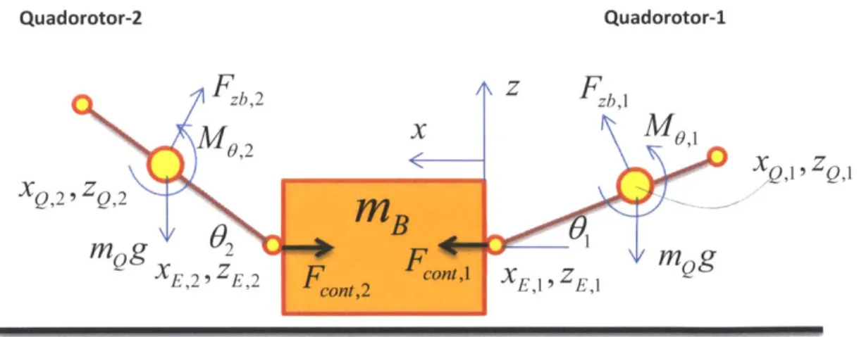
3.3.5 Dynam ics of Two Quadrotors M anipulating an Object ... 52
3.3.6 An Alternate Representation ... 55
3.3.7 Com plete Derivation of X X 2 Dynam ics... 58
mnamp,l~ nmamp,2 3.3.8 Contact Stability Condition for the Two Quadrotor Case ... 64
3 .4 S u m m a ry ... 7 0 4 M anipulation Using Single and M ultiple Quadrotors ... 71
4.1 Control of Quadrotor in Free Flight ... 72
4.2 Control of Quad rotor in Contact... 73
4.2.1 X Controller... 73
4.2.2 X anp Controller...75
4.2.3 Xanipi and Xnanip2 Controllers for Two Quadrotor Case ... 76
4.3 Desired Trajectories for M anipulation... 77
4.3.1 M anipulation Using a Single Quadrotor ... 78
4.3.2 M anipulation using Two Quadrotors ... 79
4.4 Sim ulation and Experiments ... 80
4.4.1 Single Quadrotor M anipulation ... 81
4.4.2 Two Quadrotor M anipulation ... 83
4.4.3 Docking and Controller Switching Approach ... 86
4.5 Experim ental Results...90
4.5.1 Single Quadrotor M anipulation ... 90
4.5.2 Two Quadrotor M anipulation ... 93
4 .6 S u m m a ry ... 9 4 5 M anipulation In the Presence of Uncertainties... 96
5.1 M anipulation In the Presence of Parametric Uncertainty ... 96
5.1.1 Adaptive Nonlinear Control ... 97
5.1.2 Im plem entation of Adaptive Nonlinear Controller...104
5.1.3 Sim ulation ... 106
5.1.4 Experim ental Results ... 108
5.2 M anipulation in the Presence of Kinematic Uncertainty...109
5.2.1 Path of Least Resistance Approach...110
5.2.2 Sim ulation Results... ... 115
5.2.3 Experim ental Results ... ... 117
5.3 Sum m ary ...---..---...--- 119
6 Design and Control of a Flexible Quadrotor ... 120
6.1 Benefits of ParaFlex over a Rigid Quadrotor... 121
6.2 Objectives... ...- .---.. --... 121
6.2.1 Objective - (1) ...-... 123
6.2.2 Objective - (2)...---- .... . --... 125
6.2.3 Objective - (3)...---...---.. 128
6.3 Sum m ary ...---. . . ----. ---... 129
7 Conclusions and Future W ork ...---... 130
7.1 Future W ork ...-.... ---... 131
7.1.1 M ulti Degree of Freedom M anipulation ... 131
7.1.2 Assistive M anipulation ... 132
7.1.3 M anipulation in GPS Denied Environm ents...132
7.1.4 Hum an in the Loop M anipulation ... 132
7.1.5 Force Feedback ...---... 132
Table of Figures
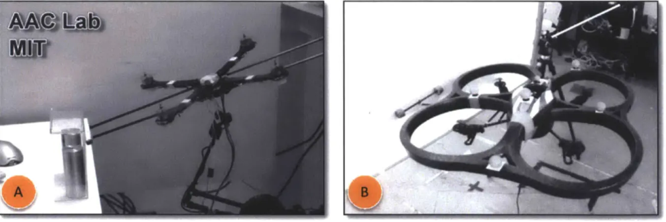
Figure 1.1: Examples of Autonomous Aerial Systems that can perform Vertical Takeoff and Landing. (A,B) Parrot AR Drone [1], (C) Ascending Tech Quadrotor, (D) Quansar QBall4, Quadrotor with a protective cage, (E) A rd uCopter w ith six rotors [2]... 17
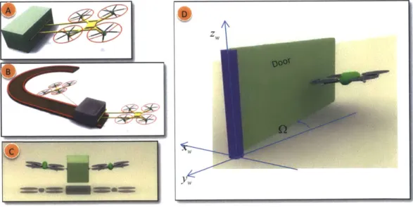
Figure 1.2: Examples of manipulation using Autonomous Aerial Systems (AAVs) or Unmanned Aerial Vehicles (UAVs). (A) A Quadrotor UAV pushing an Object. (B,C) Two Quadrotor UAVs pushing-pulling an O bject, (D) Q uadrotor UAV opening a door. ... 17
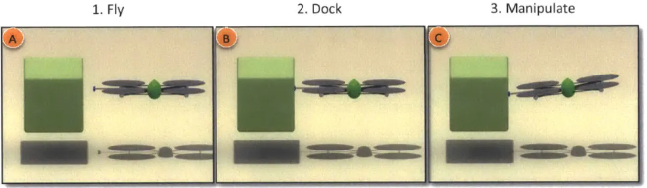
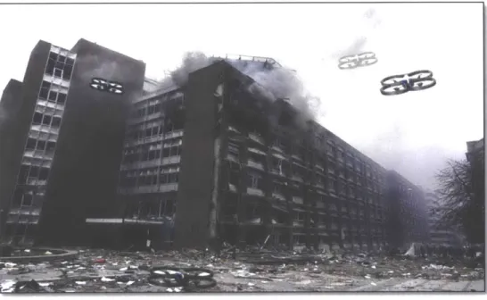
Figure 1.3: The basic approach in manipulation. (A) The UAV flies to close proximity of the target Object. (B) UAV docks to the object by means of an end-effector, and (C) UAV performs manipulation by applying a force. In (A) the UAV is in flight mode with flight dynamics at play, and in (B,C) the UAV is in manipulation mode where both flight and manipulation dynamics are at play. After the manipulation process, the UAV undocks and enter into flight mode as in (A)... 18 Figure 1.4: Illustration: A disaster stuck place (Oslo, Norway, 22 July, 2011). Overlaid on top are the Aerial Vehicles, equipped with manipulation capability, can readily fly and reach the top floor where search and rescue operation can be executed ... 20 Figure 1.5: Performance comparison of Ground Robot with Aerial Robots during a search and rescue mission. In (A,B,C), a ground robot has to traverse a rough and unknown terrain, and may take
prohibitively long time to reach the location. In (D,E) a set of Quadrotor UAV reach the location much faster than the ground robots. Because they can perform manipulation, they cooperatively open the window and let themselves inside. They then perform the necessary manipulation tasks, such as moving hazardous item s out of the way, or clearing the space... 20 Figure 1.6: AAV based manipulation carried out at GRASP Lab of UPenn [12, 13, 19-21]. (A) Three
Quadrotors cooperatively carry a payload using cables are the interface. (B) A Quadrotor is equipped with a gripper that can grasp an object. (C) Using gripper, the Quadrotor assembles the individual pieces to fo rm a stru ctu re ... 24 Figure 1.7: (A) A helicopter with gripper designed at Yale to pick and carry a payload [15]. (B) A group of aerial vehicles designed at ETHZ to dock with each other to form a larger platform [17, 18]. (C) A ball juggling Q uadrotor designed at ETHZ [16]... 24 Figure 2.1: A block diagram representation of STeVE showing some of its key components...29
Figure 2.2: HIL Setup Utilizing a Force-Torque sensor to measure the Actuator generated forces. Equations show the Thrust and moment generated as a function of propeller speed and other system co n sta n ts ... 3 1 Figure 2.3: The fabricated setup of HIL with a Force-Torque sensor. (A) shows the schematic with the actual force-torque sensor shown in the inset. (B) Shows the instrumentation system mainly consisting of analog-to-digital and digital-to-analog converters. The large size of is due to large power drivers for the motors. The computer housed the LabView NID DAQ cards for data acquisition. (C) Shows a DRAGAN FLY Quadrotor frame consisting of brushed DC Motors. (C) Shows Ascending Tech Quadrotor frame with b rush less 3-p hase m oto rs... 32
Figure 2.4: Experimental result of force measurement. The actuator is given an a constant input to generate a fixed lift force of 0.76N. When an obstacle is introduced 12 inches below the propeller, lift force increased by about 0.1N. The plot shows the fluctuation of the lift force as the obstacle was re peated ly intro d uced. ... 33
Figure 2.5: HIL Test Facility showing Quadrotor mounted on a motion sensing platform. Here the
Quadrotor is free to m ove in a confined space. ... 34 Figu re 2 .6 : End-effecto r designs. ... 35
Figure 2.7: End-Effector design showing the joints and degrees-of-freedom... 36 Figure 2.8: End-effectors used in experiments. (A) Application of design shown in Figure 2.6(B). (B) Use of design show n in Figure 2.6 (D ). ... 37 Figure 2.9: The architecture of flight test environment. The position and orientation of the UAVs are sensed by Vicon Motion Capture System [26]. An interface program reads the position and orientation from the network and forwards it to the control/simulation module. The control system then computes the control commands which are then forwarded to the UAVs via WiFi via the interface program. The
interface program manages various events including initialization, take-off and landing. It is also
responsible for visualization and data logging. ... 37 Figure 2.10: Q uadrotor Control Loop. ... .38 Figure 3.1: Coordinate system for the Quadrotor UAV ... 40 Figure 3.2: (Left) Top view of Quadrotor docked to the object showing the end-effector in contact with the object. (Right) The end-effector mechanism degrees of freedom... 44 Figure 3.3: Sim plified m odel for X _n dynam ics. ... 46 Figure 3.4: Two Quadrotors docked to the Object on either side apply a collective force to achieve bilateral manipulation. The top schematic is the top-view and the bottom schematic is the side-view... 54
Fig u re 3 .5 : Reg io n o f stab ility ... 68
Figure 3.6: Region of stability. The black trace enclosing region5 corresponds to the subspace of
LF]
Fbject that satisfies contact stability. As expected, F > 0 suggesting a positive graspFobject,grasp _
force, and Foybec, has both positive and negative excursions... 69 F
Figure 3.7: region5 enclosed within the black trace is the region of permissible subspace for object LFobject grasp
j
. ... 7 0
Figure 4.1: Basic steps in manipulation. (A) The UAV flies close to the object and ensures the end-effector is located at the designated docking position on the object. Here the UAV is in free-flight mode and uses a free-flight controller to perform this step. (B) The UAV docks to the object, at which point the contact dynamics is applicable. From this point onwards, the controller is switched to manipulation controller. (C) By applying a desired amount of force, the UAV performs the manipulation. After the manipulation, the UAV is undocked and the controller is switched to free-flight controller...71 Figure 4.2: Single UAV pushing an Object with a desired push force. The plot shows the desired angle
Ode, (t) that corresponds to a desired push force F .The resulting 0(t) and the push foces
F,sh(t) are shown. The forces are maginified 10 times for visibility in the plot...82 Figure 4.3: Motion of the Object xE due to a single Quadrotor pushing...82 Figure 4.4: Simulation of two Quadrotors manipulating an object with a sine wave reference trajectory. The maximum push force for each of the Quadrotor is F =±1.57N. As seen from the second plot, the resolved push forces are w ithin the lim its. ... 84
Figure 4.5: Simulation of two Quadrotors manipulating an object with a square wave reference trajectory. The maximum push force for each of the Quadrotor is F = ±1.57N. As seen from the
second plot, the resolved push forces are within the limits. However, 01,02 are occasionally exceeding
Omax = 20' because of the ignored dynam ics. ... 85 Figure 4.6: Impact experiment to compare the performance of Free-flight controller with Manipulation C o n tro lle r...8 7 Figure 4.7:
0(t)
plots for Free-Flight (above) and Manipulation (below) controllers...87Figure 4.8: Green trace - Quadrotor is in free-flight with free-flight controller Blue trace - Quadrotor is in free-flight, however is commanded by the manipulation controller. The reduction in performance is
acceptable in view of the benefit of robustness... 88
Figure 4.9: (A) Shows the docking simulation setup. (B) The Quadrotor running the free-flight controller becomes unstable and flips over. (C) The Quadrotor running the manipulation controller remains stable. ... ... 8 9 Figure 4.10: Single Quadrotor experimental setup showing the Quadrotor and the Object. The Object is free to move on the track. The white balls on the cart and UAV are the retro reflectors that are used by the motion capture setup to track the position and orientation. ... 90
Figure 4.11: The Quadrotor is docked (left) and is pushing the cart (right) by making 0 > 0 ... 91
Figure 4.12: Experim ental result of 0 tracking. ... 91
Figure 4.13: Desired force Fshdes (t) and the actual push force Fpus (t) ... 92
Figure 4.14: The position of the Object XE and the angle 0 ... 92
Figure 4.15: Experimental setup for two Quadrotor manipulation system. The Object is a flat foam core weighing about 4Kgs. The two Quadrotors are in docked state. ... 93
Figure 4.16: Object position xE due to a commanded sinusoidal input. The two Quadrotors are docked at t=15sec. One complete cycle of sinusoid position command is executed. The corresponding simulation resu lt is sho w n in Fig u re 4 .5 . ...--.... 94
Figure 5.1: Region of instability shown in shaded area within the ellipsoid. ... 104
Figure 5.2: Tracking performance when only the PD controller is active. (A) Shows the reference command Xd,, (t) . (B) Shows the tracking error when the mass of the system m. changes by 25%. (C) Show s the corresponding control inputs... 106
Figure 5.3: Tracking performance using Adaptive Nonlinear Controller. (A) Shows the reference command. (B) Shows the tracking error when the mass of the system changes by 25%. The mass is increased at around t=14sec, and decreased at around t=22sec. (C) shows the net control inputs computed by the controller. (D) Shows the contribution of adaptive controller towards the control input. The adaptive controller is silent elsewhere, and starts to contribute only when the system parameters have changed ... ...---.. 107
Figure 5.5: Plots shows the tracking error z(t)-zde,(t) in centimeters and O(t)-Od,1 (t) in degrees, for a reference input of Ode(t) = 20 , and z(t) = rsin Ode ... 108 Figure 5.6: Quadrotor end-effector is docked to the door at Pdock .By applying force, the Quadrotor
pushes the door by to rotated it by an angle Q. Xf,,e of the Quadrotor is controlled to ensure the applied force is always normal to the door, which means the Quadrotor yaws as the door rotates. Figure on the left shows the profile view, while the figure on the right shows the perspective view. ... 110 Figure 5.7: Top view of door opening manipulation showing the docking positions and differential m easurem ent of the door dock positions. ... 113 Figure 5.8: A general case of kinematically constrained Object manipulation on a 2D surface. ... 114 Figure 5.9: Door opening simulation. In the plot on top, the door angle Q is measured while in the bottom plot, the estim ated door
o
angle is used. ... 116 Figure 5.10: Manipulation of object constrained to move on an arbitrary trajectory (brown dotted lines). The red-trace shows the End-effector trajectory. The Object is overlaid on top of its trajectory. A disturbance was introduced to the Quadrotor when the Object was at y=900mm, x=750mm, which caused it the end-effector PE to deviate from dock position Pdok ... 116Figure 5.11: Door with hinge located on the left side. The distortion in the image is due to use of wide-a n g le le n s ... 1 1 7 Figure 5.12: Another view of the experiment showing Quadrotor along with the end-effector docked to th e d o o r. ... 1 1 7 Figure 5.13: Experimental result of Quadrotor opening the door. Case-1: The hinge is located on the left hand side, as shown in Figure 5.11. Case-2: The hinge is located on the right hand side...118 Figure 5.14: Plot of yaw angle of Quadrotor V/, the estimated door angle C and, the actual door angle
Q. The docking occurred at around t=45sec. The Quadrotor undocked at around 57 sec. ... 118 Figure 6.1: ParaFlex Q uadrotor UAV ... 120 Figure 6.2: ParaFlex colliding with a wall. Collision force changes the deformation angle A ... 121 Figure 6.3: Simulation of ParaFlex navigating through a tight hallway. Top view shows the ParaFlex and its path. The plot below shows the forces appearing on body. Red-trace is the forces appearing on the
Figure 6.4: Version 1 of ParaFlex. (A) Shows the complete view of ParaFlex. (B) Shows the onboard computer made by X-UFO. (C) Shows the ParaFlex in relaxed state and (D) shows the ParaFlex in
deform ed state. ...---...--.. .. ---... 123
Figure 6.5: Version 2 of ParaFlex showing the protective shrouds around the propellers...124 Figure 6.6: Experimental result of ParaFlex colliding with a wall (Red-trace). Blue trace corresponds to a rigid Quadrotor colliding with the wall with same im pact velocity...125 Figure 6.7: y/ and A - tracking performance during free-flight. ... 127
2
Figure 6.8: Performance of nonlinear controller on flexible Quadrotor. The red trace is the collision performance of a rigid Quadrotor using a baseline free-flight controller. Blue trace is the collision performance of a rigid Quadrotor with the controller presented in Chapter-4.4.3. The Magenta trace is the collision performance of a flexible Quadrotor using the controller of Chapter-4.4.3. The effective area covered under the curve is indicative of robustness...128
1 Introduction
1.1
The Big Picture
Figure 1.1: Examples of Autonomous Aerial Systems that can perform Vertical Takeoff and Landing. (A,B) Parrot AR Drone
[1], (C) Ascending Tech Quadrotor, (D) Quansar QBall4, Quadrotor with a protective cage, (E) ArduCopter with six rotors [2].
Figure 1.2: Examples of manipulation using Autonomous Aerial Systems (AAVs) or Unmanned Aerial Vehicles (UAVs). (A) A Quadrotor UAV pushing an Object. (B,C) Two Quadrotor UAVs pushing-pulling an Object, (D) Quadrotor UAV opening a door.
The fundamental focus of this thesis is to technologically empower the aerial vehicles, such as the ones shown in Figure 1.1, to perform manipulation tasks as shown in Figure 1.2. Autonomous Aerial Vehicles
(AAVs), also referred to as Unmanned Aerial Vehicles (UAVs) shown in Figure 1.1, are able to hover and navigate in space using the thrust forces generated by the propellers. While AAVs/UAVs have been predominantly used for "fly and sense" applications, they can also be used for "contact" based applications. With intelligent redesign, the thrust forces can also be utilized to apply forces to a target Object, thus inducing a motion. The UAVs first fly close to the Object and safely docks to it. While maintaining stable flight, a controlled amount of force is applied to the Object. As the Object starts to move, the UAV continuously ensures flight stability as well as docking stability. This is illustrated in Figure 1.3. While a single UAV is limited in the manipulation capability, multiple UAVs can cooperatively perform more complex manipulation tasks, as shown in Figure 1.2(B,C).
1. Fly 2. Dock 3. Manipulate
Figure 1.3: The basic approach in manipulation. (A) The UAV flies to close proximity of the target Object. (B) UAV docks to the object by means of an end-effector, and (C) UAV performs manipulation by applying a force. In (A) the UAV is in flight
mode with flight dynamics at play, and in (B,C) the UAV is in manipulation mode where both flight and manipulation dynamics are at play. After the manipulation process, the UAV undocks and enter into flight mode as in (A).
While efficient flight control of UAVs has been an active research area, using them to perform manipulation by contact is novel and challenging because of the dual goal: perform manipulation and maintain stable flight. The focus of this thesis is the development of a number of Quadrotor designs and control strategies in order to carry out autonomous manipulation.
In the proposed approach, the UAV uses a lightweight, passive end-effector mechanism to interface with the Object, as shown in Figure 1.3(C). As a result, the dynamics of the UAV is coupled with that of the Object with several free degrees of freedom. Careful design choices have to be made to ensure that the aerodynamic coupling is minimized, which otherwise would complicate the dynamics. A nominal flight controller fails to stabilize the UAV during a contact event. Designing stable and efficient manipulation schemes requires a thorough understanding of the new dynamics. Unlike in free-flight scenarios, the UAV has to perform more precise maneuvers in order to carry out the manipulation task, thus placing stringent requirements on controller performance. When multiple UAVs manipulate a single object, the
resulting complex dynamics has to be systematically simplified and modularized in order to make control design possible. When some of the system parameters are unknown, carryout manipulation becomes inefficient and sometimes impossible. Adaptive control schemes have to be designed to address this issue. While intentional contact is used to perform manipulation, accidental contacts can occur during a free-flight operation and may potentially damage the UAV. In order to robustify the UAV to accidental contacts, control based solution can be obtained, but this alone will not suffice. Therefore, a UAV design solution has to be provided. To address this, a flexible Quadrotor design, designated as ParaFlex, is proposed. These discussions imply that new methods have to be developed for the design and development of novel Quadrotors that are able to successfully manipulate objects while maintaining stable and robust flight. This is the focus of the thesis.
We first derive a dynamic model of the Quadrotor that accounts for the presence of contact, Object dynamics and kinematics. To improve manipulation performance, a passive light-weight end-effector interface between the Quadrotor and the Object is proposed. The complexity of the dynamics is systematically reduced by making certain assumptions. The resulting dynamic model is divided into nonlinear subsystems on the basis of their degrees of freedom, for each of which separate controllers are designed. An efficient docking approach is proposed that permits fast and aggressive docking, even at very high speeds. Because a single Quadrotor UAS is limited in manipulation capability, a multi Quadrotor cooperative manipulation scheme is proposed.
Several control strategies are proposed to deal with uncertainty, particularly in the presence of kinematic and parametric uncertainties. A Quadrotor manipulation and control scheme to open an unknown door is designed, where the door kinematics is assumed to be unknown. When the Quadrotor's parameters are unknown, a nonlinear adaptive controller is implemented to perform efficient trajectory tracking.
While establishing contact was intentional in the above manipulation tasks, contacts can occur accidentally that may lead to a crash. In order to improve robustness to accidental contacts, a novel flexible Quadrotor design is proposed to further improve the robustness.
Figure 1.4: Illustration: A disaster stuck place (Oslo, Norway, 22 July, 2011). Overlaid on top are the Aerial Vehicles, equipped with manipulation capability, can readily fly and reach the top floor where search and rescue operation can be executed.
Ground Robots Aerial Robots
Figure 1.5: Performance comparison of Ground Robot with Aerial Robots during a search and rescue mission. In (A,B,C), a ground robot has to traverse a rough and unknown terrain, and may take prohibitively long time to reach the location. In
(D,E) a set of Quadrotor UAV reach the location much faster than the ground robots. Because they can perform
manipulation, they cooperatively open the window and let themselves inside. They then perform the necessary manipulation tasks, such as moving hazardous items out of the way, or clearing the space.
A simulation, test and validation environment (STeVE) is developed to facilitate smooth transition from design to simulation to experiments. STeVE consists of several software and hardware tools, some of which are developed in house, and includes Hardware-in-the-loop test facility and actual flight systems.
In addition to validation of the Quadrotor designs and control strategies using STeVE, the efficacy of various manipulation and control schemes is demonstrated through extensive flight experiments.
1.2
Potential Applications
With the ability to fly and manipulate objects, several novel applications can be proposed. The ability to fly permits the UAVs to reach a target location with speed and efficiency. The ability to manipulate while being in the air enables them to perform tasks which otherwise would be extremely inefficient or impossible. Consider the scenario shown in Figure 1.4. A number of UAVs that are manipulation capable can readily fly to the top floor of the building where a search and rescue mission has to be performed. If for instance a window or a door needs to be opened to enter, the AAVs can perform such an operation. The main advantage here is the time to reach the location, which is in the order seconds. If a ground robot, like the ones shown in Figure 1.5 (A,B,C) have to reach the location, they may take several minutes to reach because of traversability issues. Once inside the building, UAVs can perform various tasks, some examples shown in Figure 1.5 (D,E).
Another example is remote assembling, where a set of UAVs can move and assemble deployable tents before humans could reach there. UAVs can perhaps help disabled open doors or clear their path as they navigate an unknown environment. They can also be used for contact based inspection or repair, for example, ship or building exterior inspection. They can also aid other larger systems, for example a
heavy crane can lift a large object while smaller UAVs can push the object to precision maneuver.
The proposed approach utilizes dynamics contacts in order to dock and apply forces to another object. Recently, several groups have used other method to perform manipulation. The following section summarizes these methods and compares them to the methods proposed in this thesis.
1.3 Prior Art
In this section, we start with prior art on UAVs in general and then present related work on utilizing UAVs for manipulation tasks.
There has been extensive research on the Autonomous Aerial Vehicles, commonly referred as Unmanned Aerial Vehicles (UAVs). Quadrotor or Multi rotor based UAVs that have the capability of hover have particularly seen more interest in recent research. Modern day mini UAVs can be battery operated for several minutes, and weigh anywhere from around few grams to few kilograms. With wireless capability, onboard sensing and powerful onboard computation capability, they are now being extensively used indoors, urban spaces, and outdoors. As of today, their main limitation are the flight time, payload capacity, and global state estimation [cite]. With the battery technology improving every day, and progress in state estimation research, the UAVs may be much more ubiquitous in the coming days. The original idea of a Quadrotor was proposed in early 1 9th century [3]. Some of the early work on
mini battery operated Quadrotors [4-6] focused on understanding the dynamics and proposed control designs. Approximation of the dynamics is often necessary in order to design a controller and therefore it is important to understand the relative importance of various components of the dynamics. For instance, in most cases the aerodynamics effects and propeller nonlinearities are ignored. [7-11] provides an extensive coverage of state of the art in UAV design, modeling and control.
While a number a research groups have focused on flight controls, only a handful of research groups have investigated the idea of utilizing UAVs for manipulation. GRASP Laboratory at University of Pennsylvania [12, 13] proposed two main methods for object manipulation using UAVs, presented in Figure 1.6. Multiple Quadrotors are connected to a single Object using cable as shown in Figure 1.6(A). An optimum trajectory is designed for each of the Quadrotor in order to carry the object [cite paper]. Although this method is well suited for pick and place task, the method requires that the cables are firmly connected before the start of manipulation, and cables have to be detached after the manipulation, demanding additional mechanism or human assistance. Another method proposed by the same group, shown in Figure 1.6(B), is to use active grippers on the Quadrotor. The gripper is driven by servo motor and can grasp an object of suitable size, weight and shape. [cite the paper] presents the control algorithms, and assembling algorithms to build a structure which is shown in Figure 1.6(C). Although quite useful in several situations, several drawbacks of this system prohibit general applicability. Firstly, the active gripper is an added weight and consumes power. For a UAV that weighs about 0.5kg, the typical payload capacity is approximately 40% (lift capacity of around 200grams with a reasonable flight time of ~15mins). The addition of the gripper (~50-100grams) reduces to the payload capacity by a significant amount. The remaining payload capacity, of the order of 20% of the UAV weight, limits the kinds of objects that can be lifted. Further, the object should have a matching feature for the gripper to obtain a successful grasp, which is very restrictive. Lastly, during lifting, the object
should be grasped at a point closer to the center of gravity. Otherwise, the off-center mass has to be countered by a torque from the UAV, which is already a torque-limited system. From the dynamics point of view, once grasped, the UAV and the Object forms a rigid body with a new mass and inertia properties resulting in a relatively straightforward control design. A minor point to add is that during picking process, the UAV is directly above the object, which means the air flow of the UAV is significantly disturbed by the shape of the Object. Control design has to account for the modified aerodynamics in order to produce corrective inputs.
Figure 1.7: (A) shows the work done at Yale University [14, 15], where an outdoor helicopter is equipped with a gripper to pick up an object. The approach is similar to that of Figure 1.6(B) [12] and suffers from the drawbacks which have been listed above. A minor point to note is that, because this is a large outdoor helicopter, picking an object on ground can be very challenging because of the ground effect. Work done at ETHZ [16-18] , shown in Figure 1.7: (B) utilizes modular UAVs to perform self-docking to become larger UAV structure. Although UAV is in contact, the goal is to create a larger UAV and not
manipulation.
[16] proposes using Quadrotors to perform juggling with a ball, as shown in Figure 1.7: (C). The position of the ball is tracked and predicted. An "impact point" is estimated where the Quadrotor needs to move to pitch the ball up. The Quadrotor is commanded to arrive at the impact point with a desired velocity such that the next hit of the ball produces a desired motion of the ball. [18] proposes using Quadrotors (equipped with a gripper) to assemble a structure with bricks. Again, the idea is similar to that shown in Figure 1.6(A).
Figure 1.6: AAV based manipulation carried out at GRASP Lab of UPenn [12, 13, 19-21]. (A) Three Quadrotors cooperatively
carry a payload using cables are the interface. (B) A Quadrotor is equipped with a gripper that can grasp an object. (C) Using gripper, the Quadrotor assembles the individual pieces to form a structure.
Figure 1.7: (A) A helicopter with gripper designed at Yale to pick and carry a payload [15]. (B) A group of aerial vehicles designed at ETHZ to dock with each other to form a larger platform [17, 18]. (C) A ball juggling Quadrotor designed at ETHZ
1.4
Key Features of the Thesis Approach
The approach used is one where the UAV contacts the object by docking and manipulates it by a combination of push forces. The first step therefore, is the selection of a suitable end-effector that facilitates safe and efficient docking and accurate and agile manipulation. The end-effector also dictates the dynamics of the overall UAV and hence the control design. Aerodynamics that enters the picture when the UAV is in close proximity to the object is also a factor. The aerodynamic effects and the selection of the most suitable end-effector are discussed in Chapter 2.
The next component of our approach is the derivation of the underlying dynamics. As this is significantly different in the case when the UAV is in free-flight versus when it is in contact with the object, we separately derive the dynamic models in both of these cases. In each, case, since the system is underactuated, we propose methods to group the dynamics into two sets, one which describes the states that influence manipulation, and those do not. These models are used both for deriving contact stability while docking and during manipulation, and for deriving control strategies for the manipulation tasks themselves. This is presented in Chapter 3.
The problem of manipulation with a single UAV is first discussed. Insights from this case are used to address manipulation using two UAVs. One of the main bottlenecks in manipulation is slow docking. We propose an aggressive docking strategy where the Quadrotor can impact an object while maintaining stable flight. This strategy is also helpful when there is an uncertainty in object's location. Chapter 4 discusses manipulation schemes using a single and two Quadrotors.
We propose two manipulation schemes when the system parameters are partially known. In the first case, we assume the object parameters, like mass, are unknown and in the second case we assume the Object kinematic constrains are unknown. The latter is illustrated through tasks such as Quadrotor opening a door whose hinge location is unknown, as well as manipulation of an object with a more arbitrary kinematic constraint. Chapter 5 discusses the control solutions in the presence of uncertainty. To address accidental contacts, and to further improve robustness, we design a flexible Quadrotor, denoted as ParaFlex. The main feature of Paraflex is a rigid frame with flexible joints, which allows a safe deformation of the vehicle with the on-set of collisions. This is addressed in Chapter 6, where the underlying dynamics, its response to collisions, and advantages over a rigid Quadrotor are discussed.
In all of the above cases, the proposed modeling approach and control schemes are validated using realistic numerical simulation followed by flight tests wherever possible. An integrated suite of tools is developed to facilitate simulation, hardware-in-the-loop tests and flight tests. This setup is denoted as Simulation Test and Validation Environment, STeVE for short. STeVE consists of various - off-the-shelf and in-house - developed software and hardware components. The main advantage of STeVE is that it enables smooth transition from conceptual design to simulation to flight experiments. The details of STeVE are presented in Chapter 2. The simulation and experimental results for each of the previously
mentioned manipulation schemes are presented in the relevant chapters.
1.5
Advantages of the Proposed Approach
The proposed method utilizes dynamic contacts and performs push-and-pull operation only. Also it does not involve air lifting. Many of the tasks in real-world can be accomplished using a combination of pushing and pulling. Example tasks are the opening of a door or pushing a cart. Because the contact is established dynamically, it neither requires preparatory work like cable attachment nor does it require specific features to grasp on to. Moreover, since we do not lift the object, the payload capacity is virtually unlimited. For instance, a Quadrotor weighing 0.5kg can typically push with a 2N force. Object weighing 10s of kilograms can be easily pushed with such forces. The only limiting factor, however, is the stick friction, which can be dealt to some degree using impact manipulation. Multiple UAVs can cooperatively push-pull an object to achieve higher degree of freedom manipulation and producing larger collective forces and torques. As will be shown later, masses of up to 4Kgs are easily manipulated using a low cost Quadrotor weighing only 400grams. The push operation is power efficient because the UAV virtually consumes almost the same amount of power as it consumes to hover.
Another advantage of our approach is due to the fact that the UAV is on the side of the Object as opposed to being on the top. As a result, the air-flow of the UAV is undisturbed. In addition, the end-effector interface design proposed in this thesis is a passive, light-weight (~10grams or 2% of UAV Weight) mechanism, which translates to significantly more flight time.
Also, the methods proposed in this thesis can also be utilized for applications requiring air lifting by having one powerful UAV lift the Object using a cable system with several light weight UAVs performing
1.6
Thesis Contributions
* The thesis presents the selection of the nature of manipulation scheme using UAVs through a combination of free-flight and docking. Through docking and application of controlled forces, the thesis presents multi-UAV, multi-degree of manipulation schemes.
* The thesis proposes design of passive, light-weight end-effector that facilitates stable docking and efficient manipulation of Objects.
* Through simulation and experiments, the thesis validates the proposed control solutions for several types of manipulation
o Dynamics for a single UAV manipulating an Object is proposed and a control scheme is presented. A reference input is design procedure based on the constraints imposed by the contact stability condition is presented. The modeling approach and control schemes are validated through simulation and flight tests.
o Dynamics for two UAVs manipulating an Object is presented. To ease the control design, a systematically reduced order, fully actuated dynamical system is derived. The necessary contact stability conditions are derived and a method to design the reference input that satisfies these conditions is presented. The proposed approach is validated using simulation and flight tests.
o The thesis proposes manipulation strategies in the presence of uncertainty. Using path of least resistance approach, a scheme to manipulate objects that have unknown kinematic constrains is presented. Through simulation and experiments, a Quadrotor opening a door with unknown hinge location is presented. When the system parameters such as the mass are unknown, the thesis experimentally demonstrates the performance of adaptive nonlinear tracking controller.
o The thesis presents a novel design for a flexible Quadrotor denoted as ParaFlex. The robustness of ParaFlex to accidental contacts is shown using simulation and experiments.
* For the purposes of validation of above mentioned schemes, a Simulation, Test and Validation Environment (STeVE) is developed. The thesis presents the components and interconnection of STeVE and how it permitted fast and efficient validation.
1.7
Thesis Organization
The thesis is organized into the following seven chapters.
Chapter 2: We present the architecture and components of Simulation, Test and Validation Environment (STeVE). Details of how the hardware-in-the-loop and flight test setup were used are presented. Various end-effector designs are presented, and their relative performances are compared.
Chapter 3: We delve in to mathematical modeling of the Quadrotor manipulation system. We present the dynamics of Quadrotor when it is in free-flight and when it is in Contact. We then derive the dynamics when two Quadrotors are manipulating a single object. We show how the complexity of the equations of motion is reduced by splitting the overall dynamics into sub systems. We derive contact stability conditions for the Quadrotors to remain docked.
Chapter 4: Using the equations of motion, we proceed to design control algorithms to perform tracking and in turn to perform manipulation. We demonstrate the efficacy of the controller through simulation and flight experiments. We demonstrate a single and two Quadrotors pushing an Object.
Chapter 5: Here we proposed solutions for more complex manipulation, like the Quadrotor opening a door. We propose control strategies to perform manipulation when some of the system parameters are unknown. We demonstrate the proposed design to manipulate objects with unknown kinematic constraints and unknown mass.
Chapter 6: While ideas presented in preceding chapters proposed stabilizing a Quadrotor when it is in contact and to perform manipulation, in this chapter we present a Quadrotor design solution. The design provides robustness to the Quadrotor in the face of an impact. We present flexible Quadrotor
design and demonstrate its efficacy through numerical simulation and flight experiments.
Chapter 7: We conclude the thesis by summarizing the results from each of the chapters. We briefly comment about the potential future work, listing specific directions.
2 Simulation, Test and Validation Environment
Simulation and Flight experiments are necessary to validate the proposed UAV designs, manipulation schemes and controls schemes. Apart from the function of validation, they also serve as a tool to aid in research. A number of findings happen within the simulation, thus cutting down expensive flight tests. Further, transitioning from simulation to flight tests can bring in unexpected hurdles, for example the Quadrotor models used in simulation are always an approximation to the real Quadrotor. A control system designed and tuned in the simulation thus may not perform well in the flight experiment. In order to address this problem, a standard practice is to use Hardware-in-the-loop (HIL) setups. HIL essentially adds realism to the simulation by replacing the model of the plant with actual components of the plant (in this case a Quadrotor). HIL permits smooth transition from simulation to flight test, isolating any design issues in the early phase. Another advantage of HIL is its ability to provide access to states of the Quadrotor which is not directly measurable in real flight experiments. For instance, forces generated by the actuators can be measured.
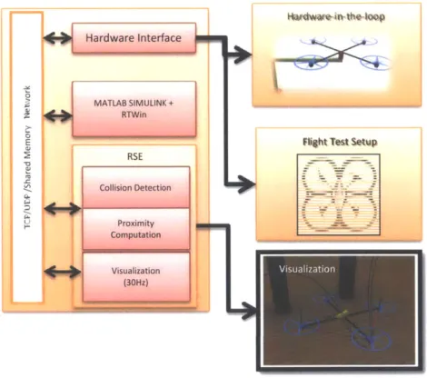
Figure 2.1: A block diagram representation of STeVE showing some of its key components.
The proposed Simulation, Test and Validation Environment, STeVE for short, is a collection of hardware and software tools to address the above mentioned goal. In this chapter, the components of STeVE are
presented, and some of key performance metrics are reported. Results from HIL experiments and how it helped make design choices are presented.
2.1
Simulation Subsystem
We used MATLAB Simulink [22] to perform most of the core computation including simulation of Quadrotor and also implementation of control algorithms. Since the Quadrotor is expected to make contact with an object, collision events have to be detected and collision forces have to be included in the simulation. This particular feature is difficult to implement in MATLAB. In order to perform collision based simulation, we resorted to another simulation tool PhysX [23], a free rigid-body simulation environment (RSE for short) package. We also extensively used MSC Nastran [24] as a replacement for PhysX. PhysX is available as a C++ library and requires extensive programming in order to build and simulate a Quadrotor and the Objects in the environment. Nastran, however provides a modeling environment to interactively build the Quadrotor body and other environmental objects. The main advantage of RSE is that it allows modeling of rigid bodies of arbitrary shapes and can perform collision
based simulation very efficiently at high rate and accuracy. We could achieve frame rate of up to 500Hz in our case using PhysX. Nastran however was non real-time, but more accurate than PhysX. The control algorithm was implemented in MATLAB Simulink, and MATLAB communicated with RSE though a communication interfaces that was developed using C++ and Communication Library Functions.
2.2
Hardware-In-The-Loop Test Facility
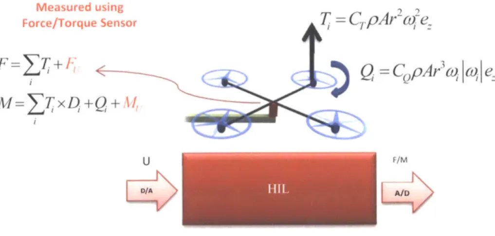
Although RSE handled collision within the simulation, it still lacks the realism of a real Quadrotor. Modeling all of the aspects of a real Quadrotor is time consuming and often impossible. To address this issue, we incorporate some of the hardware components of the Quadrotor into the simulation in order to make the overall simulation more realistic. The hardware component is interfaced to the simulation through necessary digital-to-analog and analog-to-digital converter interfaces. We propose two types of HIL setup. The first one uses a force-torque sensor is shown in the Figure-2.2. The second one uses a motion sensor as shown in Figure 2.5.
Measured using C
Force/Torque Sensor T
Ar2
F=Z
7+I1Q
=C pArq
wt, e
M=7;xD+Q+AI,
U F/M
LS >
Figure 2.2: HIL Setup Utilizing a Force-Torque sensor to measure the Actuator generated forces. Equations show the Thrust and moment generated as a function of propeller speed and other system constants.
2.2.1 Force Based HIL
In the simulation the Quadrotor is modeled using a rigid body. The actuators are modeled as a second order system with quadratic nonlinearities which arise due to propeller aerodynamics [4]. These models, however sophisticated, fail to include all of the nonlinearities of the actuator that arise due to the electronic speed controller and propeller aerodynamics. Moreover, when the Quadrotor is flying close to an object or another Quadrotor, the air flow in the propeller get disrupted, as a result causing disturbances. These aspects are hard to model in the simulation. As a solution, we replace the simulation model of the actuator with a real hardware actuator. The Quadrotor actuators, along with the frame of the Quadrotor are mounted on a force-torque sensor. The developed hardware setup is shown in Figure 2.3 and its function is illustrated in Figure 2.2. Using the HIL setup of Figure 2.3, we performed a number of experiments including (1) system identification of the actuators (2) compare different types of propellers and motors in terms of noise/vibration performance, and (3) proximity effects - when there is an obstruction to the flow of air, assess the changes in lift forces.
Since the actuator is speed controlled, the motor model was assumed to be
H
(s)
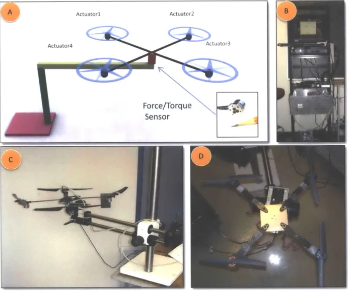
= e- 1 (2.1)Figure 2.3: The fabricated setup of HIL with a Force-Torque sensor. (A) shows the schematic with the actual force-torque sensor shown in the inset. (B) Shows the instrumentation system mainly consisting of analog-to-digital and digital-to-analog converters. The large size of is due to large power drivers for the motors. The computer housed the LabView NID DAQ cards for data acquisition. (C) Shows a DRAGAN FLY Quadrotor frame consisting of brushed DC Motors. (C) Shows Ascending Tech
Quadrotor frame with brushless 3-phase motors.
The time delay TD and the motor time constant r were identified using the system identification tool
box of Matlab. The quadratic response of the thrust force as a function of propeller speed was verified, that is
Fy,
=kw
,,,.
A quadratic function was fitted asWhere F, the lift is force and a,b,c are the constants, and v is the input to the actuator. Equation-(2.2) then was used to linearize the quadratic around the operating point in order to perform control design. In the experimental study, the best motor was found to be of brushless 3-phase type, made by
Hacker. Other motors included geared brushless motors, and geared brushed DC motors.
Proximity effects were studies using the Force based HIL. When the motor was running a fixed speed, an obstacle (a flat piece of wood) was introduced 12 inches below the propeller. This resulted in an increased lift force, as shown in the experimental result in Figure 2.4. This effect is also known as ground effect. 0.9 Obstacle (12" below 0.88t the propeller) 0.86: 0.84 -0.82 0.78
0.78 'Free Flow of Air
076 074 . 0.72 0.7 -12 14 16 18 20 22 24 26 28 Time (s)
Figure 2.4: Experimental result of force measurement. The actuator is given an a constant input to generate a fixed lift force of 0.76N. When an obstacle is introduced 12 inches below the propeller, lift force increased by about O.1N. The plot shows
the fluctuation of the lift force as the obstacle was repeatedly introduced.
2.2.2 Motion Based HIL
In the case of Force based HIL, the HIL replaced the actuators and not the Quadrotor itself. The rigid body dynamics had to be simulated by applying the forces measured from the HIL. To take the HIL one step further, a motion based HIL was developed. In the motion based HIL, instead of a fixed Quadrotor frame, the Quadrotor was free to move in a confined space, and the motion of the Quadrotor was measured. The forces generated by the actuators now act on the frame, and the simulation system uses the measured position and orientation.
The experimental setup is shown in Figure 2.5. A Phantom Haptic Device [25], a mechanical 6DoF motion sensing (and force feedback) device is used to sense the motion of the Quadrotor. It is essentially an articulated 6DoF mechanism with 6 joint angle sensors. The Quadrotor frame is rigidly mounted on the end-effector of the Phantom device. The Phantom device is equipped with high resolution (4096 counts per rotation) optical encoders at each of the joints. The encoder reading translated to angle so the joints. Using the measured angles and performing forward kinematics, the end-effector location was determined. The end-effector location corresponds the Quadrotors position and orientation, which is used in the simulation.
6DoF High-Fid Motion sensor 4: 0 H/W Interface -Motion data Control Computer: Matlab Simulink
Figure 2.5: HIL Test Facility showing Quadrotor mounted on a motion sensing platform. Here the Quadrotor is free to move in a confined space.
The key feature of the above mentioned HIL is it's agility to sense the position and orientation as a high rate of 5000Hz. Such measurement rates are usually hard to achieve in real flight experiments. The main drawback of this HIL is the parasitic dynamics that comes because of the mechanical motion sensor. Another disadvantage of course is the range of motion achievable. The workspace was limited to approximately 200mm cube. The HIL was used to evaluate end-effector designs and also to perform adaptive control based manipulation experiments, which is presented in Chapter-5.
2.3
End-Effector Design
in order to perform manipulation, the UAV has to first establish a mechanical coupling. The interface between the object and the UAV is termed as the End-Effector. The End-effector is part of the UAV, which is used to dock to the object. Since the UAV is on the periphery of the object, the air flow is not disturbed, which otherwise would have caused aerodynamic disturbances as noted in the experimental result of Figure 2.4.
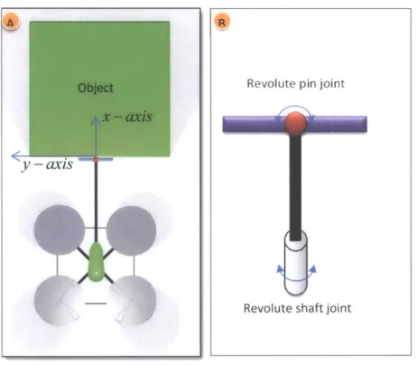
Figure 2.6: End-effector designs.
We proposed and evaluated a number of End-effector designs shown in Figure 2.6. The first design is in Figure 2.6(A), which is point-on-surface constraint. Although it is simple, because of point contact, the end-effector is not robust. The second design shown in Figure 2.6(B) is more robust because two beams and line-on-surface contact. However, when the UAV rolls about the end-effector axis, the bar touching the surface of the object slides, which produces friction torque. This is undesirable because the UAV needs to freely roll to correct for any disturbances. Obstruction to roll can lead to inefficient
FL
manipulation preformation. In both Figure 2.6(A) and (B), the contact reaction force introduces a torque on the UAV, which has to be countered through appropriate control design. As an alternative, Figure 2.6(C) shows a curved segment at the end-effector. As the UAV banks to apply the necessary force, the contact point moves in such a way that the contact reaction force does not introduce a torque. This simplifies the dynamics and also the manipulation process. The main disadvantage of this mechanism is the compliance. Because the contact reaction force is in line with the UAV center, an aggressive docking
may lead to instability. Further, the design in Figure 2.6(C) does not have the soft compliance which exists in the design of Figure 2.6(A) and (B). The final design which captures of the best features of Figure 2.6(A,B,C) is the design in Figure 2.6(D). Design of Figure 2.6(D) is essentially similar to that of the design in Figure 2.6(A), except that it has two revolute joints as shown in Figure 2.7. The joints permit the UAV to perform roll around the x-axis, and also to swivel around the z-axis (point outward from the plane of Figure 2.7). Figure 2.8 shows the experimental setup utilizing two promising End-effector designs.
Figure 2.7: End-Effector design showing the joints and degrees-of-freedom.
y -axis
Revolute pin joint
Figure 2.8: End-effectors used in experiments. (A) Application of design shown in Figure 2.6(B). (B) Use of design shown in Figure 2.6 (D).
A
a
VICON motion capture
TCP
WiFi/UDP
e
TCP Posmon and orientation
VICON MX
Giganet
Figure 2.9: The architecture of flight test environment. The position and orientation of the UAVs are sensed by Vicon Motion Capture System [26]. An interface program reads the position and orientation from the network and forwards it to the
control/simulation module. The control system then computes the control commands which are then forwarded to the UAVs via WiFi via the interface program. The interface program manages various events including initialization, take-off and
2.4
Flight Test Environment
The final validation of the control algorithms is conducted in a flight test environment. The architecture of the flight test setup is shown in Figure 2.9. The position and orientation of the UAVs are sensed at a high rate (up to 250Hz) by the Vicon Motion Capture system (26]. The date reaches the control computer by means of a TCP/IP network. An interface program developed in C++ acts as a junction block for various data streams. The position and orientation is formatted and forwarded to the control system. Matlab Simulink handles the incoming state information and computes the control command for the UAVs, which is then forward to the interface program. The interface program formats the command data and forwards it to the UAVs using UDP protocol through WiFi. All of these events happen synchronously and it is ensured that the delays is as least as possible. The interface program also provides GUI for the user and performs various additional tasks such as takeoff, landing and emergency landing.
Figure 2.10: Quadrotor Control Loop.
From the control loop perspective, there are mainly two main loops. The Quadrotor has onboard gyros that prove angular velocities. A part of the control loop, termed as onboard-control is directly
Output Thrust Yaw Pitch Roll -111.10 Nil IRWIN 1911111111"
![Figure 1.6: AAV based manipulation carried out at GRASP Lab of UPenn [12, 13, 19-21]](https://thumb-eu.123doks.com/thumbv2/123doknet/14482291.524350/24.918.135.771.114.494/figure-aav-based-manipulation-carried-grasp-lab-upenn.webp)