HAL Id: hal-00506377
https://hal.archives-ouvertes.fr/hal-00506377
Submitted on 16 Sep 2015HAL is a multi-disciplinary open access archive for the deposit and dissemination of sci-entific research documents, whether they are pub-lished or not. The documents may come from teaching and research institutions in France or abroad, or from public or private research centers.
L’archive ouverte pluridisciplinaire HAL, est destinée au dépôt et à la diffusion de documents scientifiques de niveau recherche, publiés ou non, émanant des établissements d’enseignement et de recherche français ou étrangers, des laboratoires publics ou privés.
Node contribution to the permeability of liquid foams
Olivier Pitois, N. Louvet, Elise Lorenceau, Florence Rouyer
To cite this version:
Olivier Pitois, N. Louvet, Elise Lorenceau, Florence Rouyer. Node contribution to the perme-ability of liquid foams. Journal of Colloid and Interface Science, Elsevier, 2008, 322, pp.675-677. �10.1016/j.jcis.2008.04.029�. �hal-00506377�
Node contribution to the permeability of liquid foams
O. Pitois*, N. Louvet, E. Lorenceau and F. Rouyer,
Université Paris-Est, Laboratoire de Physique des Matériaux Divisés et des Interfaces, UMR CNRS 8108, 5 bvd Descartes, 77454 Marne la Vallée Cedex 2, France.
Abstract:
This paper deals with the drainage of liquid foams. The liquid velocity is known to be related to viscous dissipation occuring within the elements of the liquid network, i.e. the channels and the nodes. When compared together, available values for the hydrodynamic resistance of a foam node appear to span over more than one order of magnitude. To clarify this point, we propose an alternative experimental method to estimate the value of this parameter. In contrast to previous experimental work performed on the foam scale, the node resistance is not treated as a fitting parameter, but instead it is measured directly on the microscopic scale. The results alow a consistent range of values to emerge for this parameter.
Keywords:
Hydrodynamic resistance, drainage, permeability, Plateau border, vertex
I Introduction
Recent experimental results [1] indicated that the permeability of a liquid foam results from both contributions of the liquid channels (Plateau borders) and their junctions (nodes). The permeability is dependent on the geometrical arrangement of the foam elements and also on the rheological properties of the interfaces that confine the liquid phase [1-4]. Two extreme regimes are expected as soon as the contribution of one element dominates the other: the
channel dominated regime and the node dominated regime [5]. The transitions between these
two regimes have been explained with the Boussinesq number - that compares the bulk dissipation with surface dissipation - as the only control parameter [1]. But, although the resistance of the channels has been found to fit this model for foam drainage, experimental [1-4] and numerical [6] studies do not allow a consistent value to emerge for the resistance of the nodes. More precisely, and as it is shown in the following, reported values span over more than one order of magnitude. The aim of this work is to clarify this point.
II Hydrodynamic resistance of foam nodes
The foam permeability is derived from the analysis of the flow on the microscopic scale, i.e. the foam network unit. For relatively dry foams, it is composed of 1 narrow Plateau border with radius of curvature r and ½ node. The total length of the unit cell L is related to the liquid volume fraction by: 𝜀 ≅ 𝛿𝜀𝑟2⁄ , with 𝐿2 0.171
[2]. Note that more complete expressions
for can be used to describe wetter foams, but as the dimensionless node resistance is expected to be independent on the liquid volume fraction, this latter relation is used in the following. Introducing the hydrodynamic resistances of the channel (Rc) and the node (Rn),
the pressure difference over the network unit is related to the liquid flow rate Q with:
c n 2
P R R Q
(1)
The volume flow rate can be related to the average velocity through the foam channels vpb and
the channel cross-sectional area Apb ar2
3 2
r2. Thus the pressure gradient over the network unit is:2 2 a pb n c r v R P R L L (2)
On the foam scale, the macroscopic pressure gradient G is related to the superficial velocity VS using Darcy’s law:
S
G V
K
(3)
where µ is the shear viscosity of the bulk liquid and K is the foam permeability (we recall that the superficial liquid velocity, i.e. the liquid flow rate flowing through the foam along a given direction divided by the cross-sectional area of the foam perpendicular to that direction, is
3
S pb
V v , where the factor 3 results from the angular average of the network units within the foam [2]). As we are solely interested in the resistance of the nodes, the resistance of the
channels will be neglected in the following, i.e. Rc0. Thus, from (2) and (3), the foam permeability is given by:
2 3 2 1 2 2 3 a n L K R (4) where 3 n n
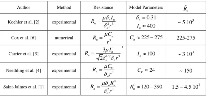
R r R is the dimensionless resistance. Several expressions are available for the foam permeability in literature. Comparisons of eq. (4) with these expressions provide several values for that can now be compared together (see table 1 for details). The values span over a large range although the foaming solutions used by the authors are similar. In fact, reported values in [2] and [1] are consistent, but it should be said that the corresponding authors used the same model for the foam permeability. In contrast, values reported in [6] and [4] are close together although the respective approaches are radically different. Considering the experimental data presented above, one can wonder if these large differences observed in the experimental values of the node resistance could be attributed to the assumptions made by the authors [1-4] about the network geometry. As the measured value for on the foam scale is model dependent - i.e. it is treated as a fitting parameter - the experimental study of a single node appears to be an interesting alternative method to estimate this value.
Author Method Resistance Model Parameters
Koehler et al. [2] experimental n 2 3n n a I R r n 0.31 400 n I 5 10 3
Cox et al. [6] numerical Rn C3n r
Cn 225 275 225-275
Carrier et al. [3] experimental
' 1/ 2 3 3 2 n n a I R r 1 ' 100 n I 3 103
Neethling et al. [4] experimental n V3 a C R r CV 24 150
Saint-Jalmes et al. [1] experimental
0 2 3 n n n a R R r 0 120 390 n R 1.5 – 4.5 103
Table 1: Comparison of available values for the node resistance
1
this expression has been deduced from [3] assuming that < 1% and given by 𝜀 ≅ 𝛿𝜀𝑟2⁄ 𝐿2
n R n R n R
III Measurement of the resistance of a single node
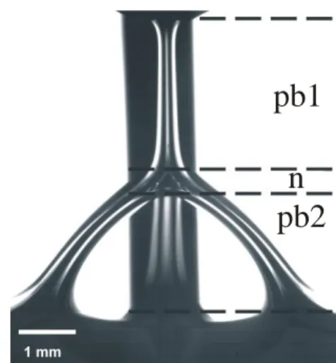
The experimental setup used in this study has been previously described and more details can be found elsewhere [7,8]. We just recall that a Plateau border and the three adjoining films are formed on withdrawing a tripod from a reservoir containing the foaming solution, and that liquid can be injected through the channel at a controlled flow rate Q. For the present study, a gas bubble is released from the reservoir with a syringe allowing a node to be generated (see fig. 1). The total pressure difference P can be measured over the system. P results from the association in series of the upper Plateau border (pb1), the node (n), and the three lower Plateau borders (pb2), themselves in parallel association:
(5)
The determination of Pn requires the pressure drops P1 and P2 to be determined. These quantities are known to be dependent on the surface shear viscosity, µS, characterizing the
interface mobility. This latter parameter has been determined from the study of a single Plateau border, as reported in [7]. Then, the geometrical features of the channels (length and cross-sectional areas) are measured from image processing performed on pictures such as the one in figure 1. We considered that the junctions between the channels and the node correspond to the points of the profile where the curvature of the interface (within the vertical plane in figure 1) abruptly change or reverse. As the cross-sectional area slightly evolves along the PBs, the channels of length can be seen as composed of a set of N small borders, each with a length li, so that
1 N i i l
. At each element i is associated the cross-section pbiA , which is determined from the channel profile, and a local Boussinesq number
1 20i S pbi a
B A . In that case, the total pressure drop P1,2 is [7-9]:
1 0.5 0 1,2 2 0.628 1,2 1 0 0.0655 0.020 0.209 N i i i pbi i l B P Q A B
(6)Note that the liquid flow rate through each channel pb2 is Q2 = Q1/3. Besides, the effect of the
longitudinal curvature of these channels is neglected in the estimation of the corresponding pressure drop.
For this study, TTAB (tetradecyltrimethylammoniumbromid 99 % purchased from Aldrich) was used in solution at a concentration C = 3 g/L (C/ CMC 3). This solution is similar to solutions used in [1-4]. With this solution, we found that µS 3-4 10-5 g/s and Bo 0.1, which
is consistent with values reported in [1] for these parameters.
1 n 2
P P P P
Figure 1: Single foam node formed at the junction of four Plateau borders. The black vertical bar is one of the frame rods.
IV Results and discussion
In figure 2, the dimensionless parameter Rn
r3
P Qn
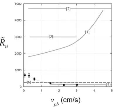
is plotted as a function of the average liquid velocity through the upper Plateau border: vpbQ Apb1 (error bars correspond to values of estimated with values of r at the inlet and the outlet of the node). For comparison, values reported in [1,2,3,4,6] are also presented: 𝑅̃𝑛 varies within the range150-700 (see insert). This behaviour agrees qualitatively with the variation previously reported for a single Plateau border [7]. At low flow rates, pressure differences become close to the accuracy of the pressure measurement so that it is difficult to attribute the observed variation to an evolution of the mobility of the interface as this latter is sheared by the liquid flow. Note that this evolution can not be compared with other experimental data as the authors reported an average value of that has been fitted to their model over the range of investigated flow rates, and that such interfacial effects are not considered in numerical simulation [6]. At higher liquid velocities, full agreement is found with the values reported by Neethling et al. The average value of our data is very close to the numerical value proposed by Cox et al. This good agreement with [4] and [6] allows a consistent range of values to emerge: 150 <𝑅̃𝑛 <
400. In contrast, the full range of data reported in this paper does not overlap with the values reported in [1-3]. Could these discrepancies be explained by the influence of the Boussinesq number ? In fact, an estimation of this influence is available in [6]: in the limit of rigid interfaces, the contribution of the node is expressed as a length correction to the Plateau borders length. The corresponding value of is not explicitly reported, but from this paper, we could estimate 𝑅̃𝑛 = 4 × 0.03 × 49 𝛿⁄ 𝑎2 ≈ 225 . Comparing this value with the one corresponding to the mobile interface, i.e. 𝑅̃𝑛 ≈ 250 ∓ 25, it appears that although a slight increase is obtained for 𝑅̃𝑛 as a function of the interface mobility, this variation is not in
quantitative agreement with figure 2, indicating that the observed discrepancies can not be explained by the effect of the interface mobility. As the values obtained for 𝑅̃𝑛 are model
dependent in [1-4], a reasonable explanation for these discrepancies could be found in the network geometry assumed by the corresponding authors. A complete evaluation of this effect remains to be done.
pb1
n
pb2
n R n R n RFigure 2: Dimensionless resistance parameter of a foam node as a function of the average liquid velocity through the upper Plateau border (see figure 1). Error bars correspond to values of estimated with values of r at the inlet and the outlet of the node.
V Summary
An alternative experimental method has been proposed to determine the hydrodynamic resistance of a foam node. In contrast to previous experimental evaluations, the node resistance is not treated as a fitting parameter, but instead it is directly measured on the microscopic scale. New results have been obtained and have been found to be in good agreement with one previous experimental work and with data obtained from the numerical study of this problem. This consistent set of values is not in accordance with the values recently proposed in the quantitative description of foam drainage, so that the present result seriously questions about the validity of this model, that overestimate the nodes resistance. Acknowledgements
We acknowledge the ANR financial support (ANR-05-JCJC-0234-01). n
References
[1] A. Saint-Jalmes, Y. Zhang and D. Langevin, Eur. Phys. J. E (2004) 53-60 [2] S.A. Koehler, S. Hilgenfeldt and H.A. Stone, Langmuir 16 (2000) 6327-6341 [3] V. Carrier, S. Destrouesse, and A. Colin, PRE 65 (2002) 061404-1
[4] S.J. Neethling, H.T. Lee and J.J. Cilliers, J. Phys.: Condens. Matter 14 (2002) 331-342. [5] M. Durand, G. Martinoty and D. Langevin, Phys. Rev. E 60 (1999) R6307
[6] S.J. Cox, G. Bradley, S. Hutzler and D. Weaire, J. Phys.: Condens. Matter 13 (2001) 4863-4869
[7] O. Pitois, C. Fritz and M. Vignes-Adler, J. Colloid Interface Sci. 282 (2005) 458-465 [8] O. Pitois, C. Fritz and M. Vignes-Adler, Colloids and Surfaces A 261 (2005) 109-114 [9] A.V. Nguyen, J. Colloid Interface Sci. 249 (2002) 194-199