DESIGN FOR MANUFACTURABILITY OF A HIGH-PERFORMANCE INDUCTION MOTOR ROTOR
by
Christopher P. Brown
B.S. Aeronautical Engineering Rensselaer Polytechnic Institute, 1994
B.A. Physics Reed College, 1994
SUBMITTED TO THE DEPARTMENT OF MECHANICAL ENGINEERING IN PARTIAL FULFILLMENT OF THE REQUIREMENTS FOR THE DEGREE OF
MASTER OF SCIENCE at the
MASSACHUSETTS INSTITUTE OF TECHNOLOGY JUNE 1996
© 1996 Massachusetts Institute of Technology All rights reserved
Signature of Author: ... ... .. .. .. ... ... ...
Department of Mechanical Engineering May 10, 1996
Certified by: ...
...
Jung-Hoon Chun Esther and Harold E. Edgerton Associate Professor of Mechanical Engineering Thesis Supervisor Accepted by: ...
.. ... . "
OF TrCHNC'.)OG •'"
Ain A. Sonin Chairman, Department Committee on Graduate Students
Design for Manufacturability of a High-Performance Induction Motor Rotor by
Christopher P. Brown
Submitted to the Department of Mechanical Engineering on May 10, 1996
in Partial Fulfillment of the Requirements for the Degree of Master of Science
ABSTRACT
A study is conducted on the state-of-the-art manufacturing practices of conventional industrial and research-and-development (R&D) firms manufacturing electric induction motors. It is found that current industrial processes cannot produce high-performance motors, and that current R&D processes are too costly. A new manufacturing process for fabricating the rotors of squirrel cage induction motors is developed. The new process addresses the issues raised by the study by delivering high performance at a reduced cost.
The induction rotor manufacturing process presented involves using net shape processes to
manufacture the parts which are manually assembled and subsequently joined. A squirrel cage of extruded chromium copper bars and end rings is used. Investment casting is used to fabricate a core of high-strength Aermet. It is shown that it is necessary to open the slots of the magnetic core of the motor in order to make effective use of investment casting and to ease assembly. The effect on motor performance of changing materials and opening slots is analyzed. The squirrel cage, impellers and shaft can be manually assembled to the core. The assembly is then joined using a diffusion bonding process. The feasibility of a Cr-Cu/Aermet diffusion bond is experimentally verified.
A systematic method of designing and optimizing a manufacturing process is presented. It is based on the experience of designing the process for the rotor.
Thesis Supervisor: Jung-Hoon Chun
Title: Esther and Harold E. Edgerton Associate Professor of Mechanical Engineering
Table of Contents
Abstract Table of Contents List of Figures List of Tables Chapter 1: Introduction 1.1 Purpose1.2 The Significance of High-Speed, High Power-Density Induction Motors 1.3 Induction Motors: Operating Principles and Mathematical Modeling
1.3.1 Induction Motor Operating Principles 1.3.2 Mathematical Modeling
1.4 References
Chapter 2: Current Manufacturing Practice 2.1 Introduction
2.2 Conventional Industrial Manufacturing Practice 2.2.1 Cold Rolled Sheet
2.2.2 Blanking Process
2.2.3 Casting the Aluminum Cage 2.2.4 Shaft Insertion
2.2.5 Summary: The Limitations on Motors Imposed by Current Practice
2.3 Current Practice at SatCon 2.3.1 Magnetic Core
2.3.2 The Glidcop Squirrel Cage 2.3.3 Shaft and Cooling Mechanisms
2.3.4 Summary: Problems Solved by SatCon Current Practice 2.4 References
Chapter 3: The Induction Rotor Manufacturing Process 3.1 Introduction
3.2 Process Overview
3.3 Functional Decomposition 3.4 The Magnetic Core
3.4.1 Performance and Assembly Requirements 3.4.2 Materials Possibilities
3.4.3 Design for Net-Shape Fabrication: The Solid Rotor with Open Slots 3.4.4 Net-Shape Fabrication Options
3.4.5 Core Manufacturing: Conclusions 3.5 The Squirrel Cage
3.5.1 Performance and Assembly Requirements 3.5.2 Materials Possibilities
3.5.3 Manufacturing Process Possibilities
22 23 24 25 26 28 29 30 30 31 33 34 35 36 37 38 41 41 43 44 53 56 56 56 57 58
3.5.4 Squirrel Cage Manufacturing: Conclusions 3.6 The Shaft
3.6.1 Materials Possibilities 3.6.2 Assembly with the Core
3.6.3 Shaft Manufacturing: Conclusions 3.7 Impeller Caps
3.7.1 Material Possibilities 3.7.2 Process Possiblities
3.8 Rotor Assembly Using Diffusion Bonding 3.9 Rotor Manufacturing Process: Conclusions 3.10 References Chapter 4: 4.1 4.2 4.3 4.4 4.5 Cost Estimate Introduction
Cost Estimate for the New Diffusion Bonded Assembly Process Cost Comparison with Other Processes
Cost Estimate: Conclusions References
Chapter 5: The General Manufacturing Process Design 5.1 Introduction
5.2 Problem Definition 5.3 Functional Decomposition
5.4 Processing and Materials Options 5.5 Production Flow Charts
5.6 Manufacturing Process Design: Conclusions 5.7 References
Chapter 6: Conclusion
Appendix A: Finite Element Analysis of Mechanical and Thermal Stresses in Open Slots 99 Appendix B: Phase Diagrams of Ni-Fe, Cu-Ni and Fe-Cu Systems 10!
Appendix C: Vendor Quotations 11
9 1
List of Figures
Figure 1.1 -The SatCon traction motor built for the Chrysler Corporation 10 Figure 1.2 - Schematic of a typical induction motor assembly 12 Figure 1.3 - The magnetic field of a number of current-turns around a ferromagnetic material 13 Figure 1.4 - Conceptual picture of the stator illustrating the three phases a, b, and c 14 Figure 1.5 -Illustration of how the three phases create a radially oriented rotating magnetic field 15 Figure 1.6 - Induction rotor schematic showing the electromagnetic interaction of one slot 17 Figure 2.1 -Conventional rotor production sequence 23
Figure 2.2 -Typical fully assembled rotor 24
Figure 2.3 - Progressive die sequence 25
Figure 2.4 -Impeller for an air-cooled motor 33 Figure 2.5 -Barsky pump for a water-cooled motor 34 Figure 3.1 -Final new production sequence for the high-performance induction rotor 37 Figure 3.2 -Exploded view of the rotor assembly 39 Figure 3.3 - Starter/Generator motor magnetic core 42 Figure 3.4 -Traction motor magnetic core with integrally machined shaft 42 Figure 3.5 -Cross section of the original core contrasted with that of an open slot core 45 Figure 3.6 -Typical wall dimensions of a closed slot core (starter/generator geometry) 45 Figure 3.7 -An illustration of the concept of leakage flux in an electric machine 47
Figure 3.8 - Slot model geometry 48
Figure 3.9 - Flux concentration due to open slots 49 Figure 3.10 - Tooth flux density vs. Slot width for open slots 50 Figure 3.11 - Efficiency vs. Slot width for open slots 51 Figure 3.12 - Power factor vs. Slot width for open slots 52 Figure 3.13 -Integral shaft/core using representative dimensions from the starter/generator 55
Figure 3.14 -Canned rotor assembly 60
Figure 3.15 -Partial assembly showing bars and end rings assembled to the core 61 Figure 3.16 -Slot shape used in the FEA with maximum stress locations shown 66 Figure 3.17 -Schematic of the diffusion bonding process 67 Figure 3.18 -Diffusion bonding using a fusible interlayer in the Cr-Cu/Aermet system 68
List of Tables:
Table 4.1 -Manufacturing process possibilities compared in this chapter 75
Table 4.2 -Summary of costs for the initial shapes of the assembly 76 Table 4.3 -Summary of operations and costs of pre-diffusion bonding assembly 78 Table 4.4 -Summary of the cost per rotor estimate for the new process 80
Chapter 1
INTRODUCTION
1.1 Purpose
When engineers design a product, they are generally faced with an array of manufacturing process options by which to fabricate it. Net-shape processes such as casting, forging, and powder metallurgy offer reasonable material properties and dimensional accuracy at affordable cost and high volume. Subtractive (material-removing) processes such as the various types of machining offer excellent and controllable part quality but at a higher cost. Still other processes can form special classes of materials (such as sheet metals or composites) at great advantage. There are hundreds of fabrication technologies, each of which has
advantages and drawbacks in terms of the geometric capabilities and the material properties of the finished product.
Often, the best process choice for one part in an assembly is not the best choice for another. The processes can also interact: using a given process to make one part may introduce geometrical options which constrain or expand the manufacturing choices for another part. Optimal joining of parts becomes an issue when an assembly contains parts which do not move relative to one another while the device is in operation. In general, an
engineer has no systematic method by which to create a manufacturing process for a part or an assembly of parts which is optimized in terms of part quality (e.g., materials properties and geometry) and cost.
The problem to be solved is: given a part, or an assembly of parts, determine the most cost-effective means of manufacturing it while maintaining a high standard of quality. A systematic method of inventing an optimized manufacturing sequence for a given assembly will be presented in abstract form in Chapter Five. The method will be developed in the context of a specific example of industrial significance: the manufacture of high power-density induction motors.
Sections 1.2 and 1.3 will explain the industrial uses and the functional principles of the high power-density electric induction motor to be fabricated. The manufacturing analysis will be focused on the rotor of the machine. Chapter Two will explain the shortcomings of current industrial manufacturing practice at making high power-density electric motors. It will also present the method currently used by SatCon Technology Corporation (SatCon) to fabricate its high power-density induction motors, in which some material choices have been made to enhance performance. While SatCon has solved some of the problems endemic in current industrial practice, the cost of their induction motors is still unacceptably high. Chapter Three will present the proposed manufacturing process and explain how it was designed. Chapter Four will present a cost estimate of the proposed production sequence and compare it to
existing processes to demonstrate its cost effectiveness.
1.2 The Significance of High-Speed, High Power-Density Induction Motors
Most technologies which use rotating machinery can derive a performance benefit from higher rotational speeds. Turbomachinery, for instance, becomes more efficient with
layers at higher flow rates. As another example, machining efficiency increases with spindle speed due to lower cutting forces. The efficiency and power-density of electric motors increases with speed due to the lower torque required to generate a given power. Lower torque requires a smaller-radius, and hence lighter, machine.
Thus, electric machines are not only themselves more efficient at high speeds, but machinery operated by electric motors/generators (e.g., HVAC, compressors, gas turbine power generators, and machine-tool spindles) are more efficient as well. High-speed (and hence high power-density) electric machines are the enabling technology for the next generation of high speed machinery of all sorts.
High speed electric machines are used to reduce the size and weight and at the same time increase the efficiency of various sorts of drive systems. Currently, electric drives are often gear- or belt-connected to the machinery which they operate. Gears introduce losses, involve higher maintenance efforts, require extra sub-systems (e.g., an oil lubrication system or a water cooling system) and generally reduce efficiencies. Recent advances in power electronics make it possible to improve motor control and realize adjustable-speed drives, eliminating the need for intermediate gears. Power electronics essentially acts as an electronic gear box [1]. The design of high and variable speed drives, however, requires a fresh look at the design and manufacturing processes used to fabricate electric motors.
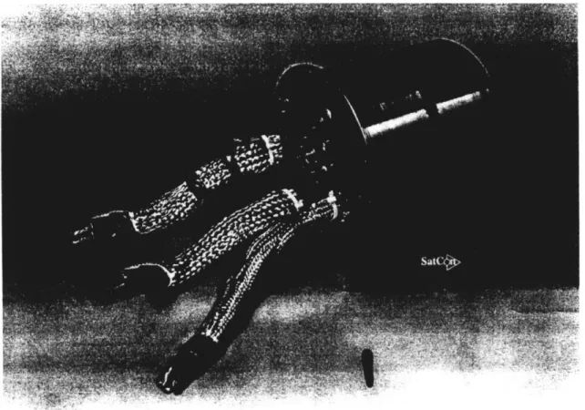
SatCon, the company which supported this research, has developed and constructed several prototype high speed induction machines for electric vehicle, aircraft APU (auxiliary power unit) and HVAC compressor applications. The traction motor shown in Figure 1.1, for instance, exhibits a power density of 3.65 kg/kW at a speed of 24,000 rpm and an output
power of 560 kW. Other SatCon motors have power to weight ratios of 3.5-4 kg/kW at speeds ranging from 60,000 to 100,000 rpm [2]. In contrast, a conventional 373 kW motor has a power density of around 7.3 kg/kW running at an operating speed of 3600 rpm [3], making it twice the weight of a SatCon motor for a given power output.
While the performance of these motors has been excellent, their utility is limited due to high manufacturing costs. The reasons for these high costs will be explored in Chapter Two, in which conventional industrial practice will be contrasted with the requirements placed on the materials and design by these unusually high power densities.
Fig. 1.1. The SatCon traction motor built for the Chrysler Corporation
Based on the experience of SatCon in assembling these motors, the most expensive parts of the assembly have been identified. The cost drivers are the rotor assembly and the stator
stack. This thesis will focus on the design for manufacture of the rotor assembly.
1.3 Induction Motors: Operating Principles and Mathematical Modeling
Clearly, the first step in devising a manufacturing process is to understand the operating principles of the machine to be manufactured. Manufacturing engineers should also have access to design principles and software that allow them to evaluate the impact of design modifications on the performance of the machine. This section contains a brief description of the operating principles of induction motors and a description of the design software used to evaluate modifications. This section illustrates how induction machines work, and puts into context the seminal geometric and materials features of the motor.
1.3.1 Induction Motor Operating Principles
Figure 1.2 shows a typical induction motor. It is primarily composed of a rotor and a stator. By applying three sinusoidal currents 1200 out of phase to the three phase windings of the stator, a radially oriented rotating magnetic field is generated which induces currents in the
bars of the rotor. The currents on the rotor and the stator interact to produce torque on the rotor. Lamination stack, Hiperco 50HS End ring
/
Shaft Coolant' passagend cap
Hub Rotor bar , Coolant line Bearings RotorSchematic of a typical induction motor illustrating the rotor assembly (above) and the rotor and stator (below)
Figure 1.2.
The process can be illustrated more clearly in the following manner. The magnetic field of a current loop (or several current loops) wound around a piece of ferromagnetic material is shown in Figure 1.3. In the loop, X indicates current flow into the page and a dot represents current flow out of the page. This configuration is that of a solenoid. The field is that of a magnetic dipole. It points along the direction of the axis of the loop, in the interior of the loop in accordance with the right-hand rule (e.g., if one points one's right thumb in the direction of the current, the fingers curl in the direction of the magnetic field).
Figure 1.3. The magnetic field ofa number ofcurrent-turns around a ferromagnetic material
The purpose of the ferromagnetic material is to increase the intensity of the magnetic field. The magnitude of the magnetic field (per unit length) in the material is given by:
B=jiNI (1.1)
where g is the permeability of the material, N is the number of turns of wire and I is the current in the wire. The permeability of air (referred to as go) is on the order of 10'7 N/A2 whereas the permeability of a ferromagnetic iron alloy can be more than this by a factor of 104
or more [4]. This leads to a tremendous increase in flux density for an applied current which, it will be seen, increases the possible torque immensely.
Figure 1.4. Conceptual picture ofthe stator illustrating the three phases a, b, and c
Suppose now that there are several current loops arranged in slots around a cylinder, as shown in Figure 1.4. The loops will create essentially radially oriented magnetic fields
(neglecting fringing fields). Now suppose that each of the three loops is connected to a source of sinusoidally varying current and that the current in each loop is 120°out of phase with the
other two. Then, as a function of time, the magnetic field in the interior of the cylinder will rotate as shown in Figure 1.5.
Figure 1.5. Illustration of how the three phases create a radially oriented rotating magnetic field
As the current in each loop reaches a maximum, the dominant field points in the direction shown. Thus, for the simple stator shown, B makes a full rotation at the same frequency as that applied to the phases. If there were more "poles", i.e., if each phase were routed to more than one loop, the field would rotate more slowly.
It is now time to insert the induction motor's rotor into the hollow cylinder with its rotating magnetic field. The time varying nature of the magnetic field will induce currents in the bars of the rotor (the "squirrel cage") due to their mutual inductance. This can be seen from Faraday's law:
VxE -
(1.2)
This shows how a time-varying magnetic field induces a perpendicular electric field. The electric field produces an axial voltage across the conducting bars of the squirrel cage. Since the axial bars of the cage are shorted to one another by the end rings, current flows through them. The rotor currents will produce torque according to the Lorentz force law for the force
on a current-carrying conductor in a magnetic field:
F=JxB (1.3)
Equation (1.3) says that the force on a current carrying conductor is perpendicular to J and B. Since J is axial and B is radial, F is circumferential, producing torque.
IMfh
Shaft
Rotor
Figure 1.6: Induction rotor schematic showing the electromagnetic interaction of one slot
This process is simplified in Figure 1.6 with an axial view of the rotor: one slot is shown, although normally there would be from 15 to 30. The time-varying radial magnetic field induces an axial voltage in the conductors immersed in it, including the ferromagnetic core of the rotor. Since the core material is generally not as good a conductor as the bars (the bars are usually made of aluminum or copper while the core must be made of some ferromagnetic alloy), currents induced in the core generate more losses than torque and are generally considered undesirable. That is why most induction rotor magnetic cores are composed of stacks of strips of sheet metal known as laminations. The thin laminations break up the axial conducting path in the core, effectively confining rotor currents to the squirrel cage [5].
Thus, the torque produced by the machine will be the force on the rotor over the surface area times the moment arm (i.e., the rotor radius) [6]:
where T is the torque developed, R is the rotor radius, 1 is the rotor length and <r> is the average electromagnetic shear. From the Lorentz force law (Equation 1.3), the
electromagnetic shear is:
r ac BX (1.5)
This says that the shear is proportional to the radial component of the magnetic field, B, and the axial component of the rotor surface current density K. The current density will depend on B (generated by currents in the stator), the rate of change of B as seen by the rotating rotor, and the mutual inductance of the stator and rotor windings, which is purely a function of the geometry of the motor.
1.3.2 Mathematical Modeling
SatCon has developed software that calculates the performance of the induction machine [7]. The model uses the geometry of the machine to calculate the mutual inductances of the rotor cage and the stator windings. From that, it can determine what magnetic flux is
produced by the stator windings and thus what currents are induced in the rotor. The magnetic flux, A, induced by a current carrying wire is proportional to the current:
A=LI (1.6)
The constant of proportionality, L, is the inductance of the loop and is solely a function of geometry. The flux is simply the magnitude of the flux density, B, times the area of the loop. The inductance of a rotor loop is comprised of a space-fundamental component, describing the flux which couples the rotor and stator and thus produces power, and a leakage component,
which takes into account flux produced by rotor and stator currents which is not mutually coupled. Thus the inductance of the rotor is [6]:
Lr = 3(pa k2N2)- L, (1.7)
Where Lr is the total inductance of the rotor, L, is the leakage component. The first term on the right-hand side is the fundamental component. For the fundamental component, N is the
number of rotor bars, k is a winding factor which is a function of the angle between the rotor bars, and goag is the air gap permeance. The permeance of the air gap is a measure of how well flux can cross the gap between the rotor and the stator [6]:
4
p
RI
a = ( ) (1.8)
7r pg
Here, R and I are the rotor radius and length, respectively, p is the number of poles and g is the effective gap length. The effective gap length is usually more than the physical gap length due to irregularities on the surfaces of the rotor and stator which affect the permeance of the gap. Rotor currents can thus be found by calculating the flux produced by the stator, and by using the geometry of the machine to calculate inductance.
With the currents on the rotor known, power developed across the air-gap between the rotor and the stator is given by:
31II'RR
P = (1.9)
where P is the power developed, the factor of three comes from the three phases in the machine, Ir is the rotor current (obtained from the fluxes and the inductances), Rr is the rotor
resistance (obtained from geometry) and s is the slip. The slip is an expression of the difference in speeds between the rotor and the stator. It is given by:
s = (1.10)
Here, Or is the rotor electrical frequency and o is the stator electrical frequency. The electrical frequencies are the frequencies at which the B-field rotates. For most machines, the slip at a point near the maximum-torque point is around 0.05. If the rotor and stator frequencies were
the same, would be zero and there would be no electric field and thus no current density in
the bars. This implies no torque.
The electrical frequency of the stator is a function of the frequency of the applied current and the number of pole pairs (i.e., in the previous section, the number of poles would be the number of current loops to which each phase is routed). Due to the phase lag inherent in
Faraday's law (i.e., the time derivative of a sinusoid is an out of phase sinusoid), the rotor field will lag or lead the stator depending on whether the machine is being used as a motor or a generator. The relation between these electrical frequencies and the mechanical speed is:
pCOm=O-C r (1.11)
where p is the number of poles and onm is the mechanical frequency.
A more detailed explanation of the mathematical modeling of an induction machine is beyond the scope of this thesis. It would include more detailed explanations of how mutual inductances are derived from geometry and how the magnetic field and flux densities through the current loops are calculated using Fourier expansions of the fundamental B-field. What is important to this thesis is to understand what is being modeled and how, and to have a tool to
evaluate the effects of changes in material properties and geometry on machine performance. In Chapter Three, a change in geometry required to simplify manufacturing will be analyzed using the concepts developed here. A Matlab code was used for the manufacturing analysis of this machine.
1.4 References
[1] Pasquarella, G., & Reichert, K. (1990). Development of Solid Rotors for a High-Speed Induction Machine with Magnetic Bearings. Technical Report. Zurich: Swiss Federal Institute of Technology.
[2] SatCon Technology Corporation. (1995). Annual Report. Cambridge, Mass: SatCon Technology Corporation.
[3] Baldor Motors and Drives. (1994). Stock Product Catalog 501. Fort Smith, AR: Baldor Electric Co.
[4] O'Handley, R.C. (1996). Unpublished Lecture Notes: Magnetic Materials. Massachusetts Institute of Technology, Cambridge.
[5] Slemon, G.R., and Straughen, A. (1980). Electric Machines. Reading, Mass: Addison-Wesley.
[6] Kirtley, J.L. (1995). Unpublished Lecture Notes: Mathematically Assisted Design of Electric Machines. Massachusetts Institute of Technology, Cambridge. [7] Kirtley, J.L. (1994). MatLab script: Polyphase Motor Design Program MOTOR.
Chapter 2
CURRENT MANUFACTURING PRACTICE
2.1 Introduction
High power densities and high speeds put unusual demands on the mechanical design of electric machine rotors. High speed implies higher mechanical stresses in the core and cage of the rotor. It also requires tighter dimensional tolerances on rotor and stator diameters, concentricities, and slot dimensions. These constraints generally increase manufacturing costs by necessitating the use of higher strength materials and exacting machining and fabrication requirements. High power density implies higher operating temperatures, higher current densities, and the use of higher permeability magnetic materials. These increase cost by requiring high-temperature materials, a copper squirrel cage, and aggressive cooling schemes.
The following two sections will put the manufacturing problem in context.
Section 2.2 will summarize current industrial practice which is able to fabricate low cost, low strength, low power density rotors. It will be shown that these processes are
incapable of making a high performance rotor cost-effectively, if at all. The current fabrication techniques used by SatCon will be the subject of Section 2.3. While SatCon's current technique can address some materials choice issues, it is unable to form these materials optimally.
2.2 Conventional Industrial Manufacturing Practice
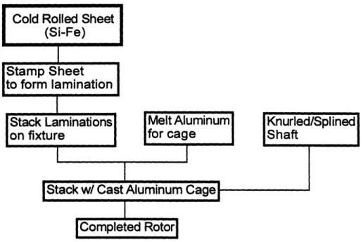
Figure 2.1 shows the basic production flow for conventional rotors for induction machines. The geometric and material properties limitations that each process imposes on the final product will be dealt with in turn.
Figure 2.1. Conventional rotor production sequence
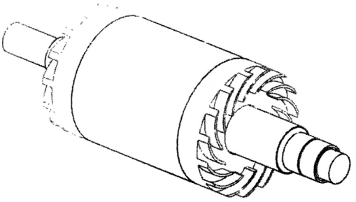
A typical, final-assembled rotor is shown in Figure 2.2. The core appears solid, rather than laminated, for clarity. The impellers on either end are used for cooling and serve as the end rings which short the bars of the cage together. The bars, being embedded in slots in the core, are not visible.
Figure 2.2. Typical Fully Assembled Rotor
2.2.1 Cold Rolled Sheet
The laminations comprising the magnetic core of the rotor must be blanked from rolled sheet. The rolling process introduces a lower limit on the thickness of laminations that can be used (of about 0.1mm thick) [1] and increases the brittleness of the material
due to cold working. The material most commonly used for fractional horsepower motors is low carbon steel. For somewhat higher horsepower applications, where core losses necessitate the use of a magnetically softer, lower conductivity material, iron alloyed with 0.5wt% to 3.5wt% silicon is used. Silicon lowers the electrical conductivity of the iron, leading to lower eddy current losses during operation of the motor. Common motor applications use 24 to 29 gauge (0.6mm to 0.343mm, respectively) laminations [1].
Lower core losses are obtained using "thin" lamination sheets, of 0.1-0.17mm thicknesses [2]. The mechanical strength of silicon-iron is adequate for most low speed applications, having ordinarily a yield strength of around 380 MPa. Cold rolled silicon irons typically have tensile strengths of around 413-448 MPa [1]. A conventional 75 kW motor has a rotor diameter of about 50 cm and a rotational speed of 3600 rpm, maximum [3]. The inertial stresses induced are a maximum on the inner diameter of the rotor and are about
180-200 MPa.
2.2.2 Blanking Process
The rolled sheet must be blanked to a particular shape, stacked to the proper height, and fastened together by riveting, bolting, welding, or the use of an adhesive. The
sheet is blanked in either a progressive or a single station die. The former is used for high volume applications and has the disadvantage of being inflexible. The single-station die
is used for shorter production runs and the shape of the lamination can be changed more easily. A progressive die sequence producing both rotor and stator laminations is shown in Figure 2.3.
Figure 2.3. Progressive die sequence [4]
5 4 3 2 stotion I
00
:.... Moter remoeinsov I 2 EM, 3:3, 4,ilem5El,
--The blanking process is basically a shearing process. It introduces burrs at the edges of the lamination and harms the flatness of the sheet. The dimensional tolerances available from a typical progressive die are as follows. The thickness of the sheet has an error of ±0.05mm, burr size has a maximum around 0.05mm and the tolerances on other dimensions are ±0.05mm per mm of the dimension in question [5].
Excessive burrs can lead to stacking difficulties, and can provide an axial conducting path across sequential laminations, degrading the efficiency of the core. Stacking warped laminations leads to gaps between the laminations. These gaps
represent lost volume of magnetic material in the core. This lost volume can increase the necessary stack length by up to 10% [5]. To make up for this, cores must be longer to contain a given volume of magnetic material. This is especially true for thin laminations, where flatness is more difficult to maintain and burrs are larger relative to total thickness. The loss of volume is expressed as a stacking factor, which is the ratio of actual volume of iron to the measured stack length times its cross sectional area.
2.2.3 Casting the Aluminum Cage
After the stack has been assembled and fastened, the conducting bars are poured directly into the rotor slots to form the squirrel cage. Vertical and horizontal cold chamber die casting are the most commonly used processes to perform this task. The former is used more often for larger motors while the latter is used for smaller (fractional
horsepower) motors. Centrifugal and permanent mold casting are also used to a lesser extent.
To obtain a good casting, the laminated stack must be assembled accurately, be free of burrs, and be placed properly in the mold cavity. Burrs create turbulence in the flow of molten aluminum and lead to voids. Proper placement of the stack in the mold helps ensure fewer cracks and inclusions in the bars due to shrinkage and differential thermal expansion between the stack and the bars.
The aluminum alloys used are primarily the rotor alloys specified as 100.0, 150.0, and 170.0. They are 99.0%, 99.5% and 99.7% pure aluminum, respectively. More impurities in the aluminum make casting easier in terms of better crack resistance and less shrinkage. However, higher impurities mean lower conductivity. For instance, rotor alloy 170.0, the purest of the rotor alloys, has an electrical conductivity of 60% IACS (International Annealed Copper Standard) at room temperature. This number changes only slightly for the remaining two alloys, down to 56% IACS for the 100.0 [6]. Commercially pure copper, in comparison, has an electrical conductivity of 0.568 (•.9-cm)"', which is defined as 100% IACS [7].
Due to its low conductivity and strength (relative to copper), the use of aluminum as the squirrel cage material clearly puts a limitation on the speed and power density of the induction machine. So why not cast copper bars into the rotor as is done for
aluminum? There are several problems with this idea. The aluminum casting alloys melt at around 580*C while copper alloys melt at about 10800C. This makes it very
If made of silicon iron, the stack in the magnetically annealed condition can only be raised to around 750 *C before seeing degradation in its magnetic properties. So it is quite possible that a melt of 1100 'C copper would at least locally degrade the properties of the stack.
In spite of these difficulties, one company, THT Presses, does have a patented copper squirrel cage casting technique. Since the technique is proprietary, it is unknown exactly how the problems are overcome. The process has been described as a
modification of the high-pressure vertical die casting process commonly used for aluminum (Ted Thieman, personal communication, July, 1995). The results of the process will be described in more detail in Section 3.5.
2.2.4 Shaft Insertion
Most shafts in conventional motors are centerless ground bar stock, inserted using a spline and a thin layer of epoxy resin to resist spline corrosion and eliminate the gap between the shaft and the core. The formation of the spline does require an extra broaching operation on both the rotor core (internal) and on the shaft itself (external). The broaching operation is a fast, accurate process which produces a reasonably good surface finish on both the internal and external faces.
Tolerances required on the spline are not all that tight. For instance, on a 10 kW motor with a 25.4mm shaft, the tolerance on the major diameter of the spline is +0.76mm, -0.00mm [8]. This is not difficult to achieve.
2.2.5 Summary: The Limitations on Motors Imposed by Current Practice
The limitations of current industrial practice can be listed as follows:
* Strength Limitations: silicon iron laminations typically have yield strengths around 380 MPa with tensile strengths around 413-448 MPa, making them relatively weak and brittle. The more costly cobalt iron laminations used for some high
performance applications can have yield strengths upwards of 520 MPa [9]. This still puts a severe limitation on the rotational speed of a motor of sizable radius. Additionally, the aluminum used in the cage yields at 100 MPa, potentially making it the strength-limiting material.
* Electrical Performance Limitations: The aluminum used for the squirrel cage has an electrical conductivity of less than 60% IACS while even high strength copper alloys have conductivities of above 85%.
* Dimensional Limitations: The dimensional accuracy of the stack is limited by both the stamping and the stacking processes. For example, the inaccuracies are such that on a 76mm round stack, the OD cannot be held to better than ±0.25mm [5]. For a high performance machine this can be 50% or more of the design air gap.
* Cost Limitations: the stamping process used to make the laminations is very capital-intensive and is only cost effective in large volumes. It is also expensive to change geometry.
2.3 Current Practice at SatCon
SatCon's method to date of manufacturing high performance electric motors has addressed several of the materials choice issues that limit the performance of
conventional motors. However, since SatCon has been involved primarily in making prototypes, the materials are not formed optimally. The following sections describe the materials substitutions currently made by SatCon to overcome the shortcomings of low power density machines.
2.3.1 Magnetic Core
The choice of magnetic core material for a high power density motor is primarily dictated by strength considerations. According to finite element analyses performed at SatCon, for a motor with rotational speeds of 60,000 rpm and a diameter of 110mm (e.g., the SatCon low speed turbine alternator), the stresses on the inner diameter of the core can be upwards of 1450 MPa. These stresses rule out the use of silicon iron or cobalt iron laminated cores. The metals are simply too weak, and the lamination of the core
dangerously decreases the stiffness of the core/shaft. This leads to the fundamental shaft mode being at frequencies very close to the rotational speed.
Some of the lower surface speed motors can use the higher strength but more expensive Co-Fe alloys. Even these alloys, however, are too weak for the very high stress applications. For these, the solid rotor material Aermet 100 (Aermet) [11.1% Ni,
Aermet, though it has inferior magnetic properties, has a yield strength of upward of 1725 MPa, giving it more than adequate strength for even the most demanding applications.
Both of these alloys are formed using the Electric Discharge Machining (EDM) process for final shaping. In the case of Co-Fe alloys, this is done because the material is very brittle, and thus sensitive to vibratory cutting forces. In the case of Aermet, EDM is used as a finishing operation because the toughness of the material makes it difficult to machine conventionally, and because of the complex shape of the slots. Tolerances on the core are very tight since everything that gets assembled to the core (e.g., bars, end rings, shaft and cooling mechanisms) are press fit to it. Another advantage of EDM, especially when used to form magnetic alloys sensitive to heat treatment, is the relatively small heating zone in comparison to conventional machining. Unfortunately, EDM has a relatively slow material removal rate, making it less than optimal for volume applications [11].
2.3.2 The Glidcop Squirrel Cage
SatCon uses a cage of machined Glidcop bars instead of a die cast aluminum cage. Glidcop is a patented, dispersion-hardened copper alloy [Cu/A1203], made by mixing copper powder with particles of aluminum oxide and sintering the product. The oxide particles both strengthen the copper and allow it to maintain its properties at high temperatures of up to 700 OC. It has higher strength than pure copper and maintains its electrical and mechanical properties even after prolonged exposure to high temperatures [12]. The highest operating temperature of SatCon's motors is 200 *C.
The highest stresses in the squirrel cage are those arising from centrifugal forces. Like the magnetic core, these stresses are highest at the inner diameter of a rotating toroid. Thus they are found at the inner diameter of the end rings. For example, the stresses on the inner diameter of the 76mm OD -38mm ID end ring found on the SatCon starter-generator induction motor are around 310 MPa. This is far above the yield
strength of aluminum and a little above that of pure copper.
Glidcop has superior strength at some sacrifice of electrical conductivity. There are three grades of Glidcop, reflecting three concentrations of the aluminum oxide particles that strengthen the material. As the volume of alloying particles increase, the
strength increases and the electrical conductivity decreases. Hence the grade with the highest strength (AL-60) has a yield strength of 503 MPa and an electrical conductivity of
78% IACS while the grade with the lowest strength (AL- 15) has a yield of 310 MPa and a conductivity of 92% IACS [12].
To fabricate the squirrel cage, the Glidcop is machined to very exacting tolerances and press fit into the slots of the core. The end rings are machined and press fit to the bars. To ensure continuity of electrical conductivity from the bars to the end rings, the assembly is brazed with a silver-based alloy. To prevent the diffusion of silver into the bulk of the Glidcop, which would lower both the strength and electrical conductivity of the cage, the Glidcop must first be electroplated, making the brazing procedure
2.3.3 Shaft and Cooling Mechanisms
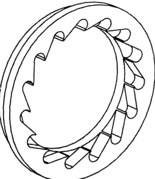
The shafts of SatCon's motors are fabricated and assembled in two ways. Some motors' shafts are centerless and cylindrically ground bar stock shrunk fit into the core. Other shafts are machined integrally with a machined core. Cooling mechanisms vary from motor to motor depending on whether they are water or air cooled. Air cooled rotors have machined impellers of 4340 steel press fit onto the end rings on either side of the rotor (Figure 2.4). Water cooled rotors have machined, 4340 steel water impellers called Barsky pumps press fit onto either end (Figure 2.5). The pump provides a pressure rise at one side of the rotor and a drop at the other in the fashion of a compressor/turbine pair. The water flows through axial holes in the rotor.
Figure 2.5. Barsky pump for a water-cooled motor
2.3.4 Summary: Problems Solved by SatCon Current Practice
The main problems that have been solved by SatCon involve using higher
performance materials for higher performance motors. High speeds require high strength materials for the magnetic core and the squirrel cage. High power densities require high
conductivity materials and materials that can operate adequately at high temperatures. These problems have been addressed by materials substitutions.
The problem of optimal forming of the materials remains. Currently, all parts are machined and mechanically press fit together. The materials are slow to machine, especially to the tight tolerances required for mechanical fitting. This main problem will be addressed in Chapter Three.
2.4 References
[1] Metals Handbook (1990). Metals Park, OH: American Society for Metals. [2] Arnon Data Sheet (1995). [Arnold Engineering Company]: Marengo, IL. Arnold
Engineering Company.
[3] Stock Product Catalog 501 (1994). [Baldor Motors and Drives]: Fort Smith, AR. Baldor Electric Co.
[4] ASM Handbook, Vol. 14: Forming and Forging (1995). Materials Park, OH: ASM International.
[5] Tempel Steel Services Division (1993). [Tempel Motor Laminations]: Niles, IL Tempel Steel Company.
[6] ASM Handbook, Vol. 2: Non-ferrous Materials: Properties and Materials Selection Guide. (1995). Materials Park, OH: ASM International.
[7] Avallone, E. A. (ed.) (1987). Mark's Standard Handbook for Mechanical Engineers, 9th ed. New York: McGraw-Hill.
[8] Machinery's Handbook. (1994). New York: Industrial Press.
[9] Alloy Data Sheet: Hiperco 50 HS (1995). [Carpenter Steel Division]: Reading, PA. Carpenter Technology Corporation.
[10] Alloy Data Sheet: Aermet 100 (1995). [Carpenter Steel Division]: Reading, PA Carpenter Technology Corporation.
[11] Kalpakjian, Serope. (1995). Manufacturing Engineering and Technology. Reading, MA: Addison-Wesley.
[12] Glidcop: Copper Dispersion Strengthened with Aluminum Oxide (1994). [SCM Metal Products]: Research Triangle Park, NC. SCM Metal Products.
Chapter 3:
THE INDUCTION ROTOR MANUFACTURING
PROCESS
3.1 Introduction
This chapter will describe the induction rotor manufacturing process in detail, describe its inherent trade-offs, list the possibilities considered, and demonstrate some of general principles of this kind of manufacturing process analysis. A generalized approach to devising the most effective manufacturing process will be presented in Chapter Five.
Section 3.2 will give an overview and flow chart of the complete process. The sections following will detail each step and each process considered. Section 3.3 will discuss the functional decomposition of the rotor into its components. This conceptualizes the function of each part to ensure no duplication of function across various parts and to focus the design so that no parts or materials have properties or features that do not relate to their function. Sections 3.4 through 3.7 will describe the techniques and trade-offs involved in each functional component. Section 3.8 will detail the chosen diffusion bonding assembly process.
3.2 Process Overview
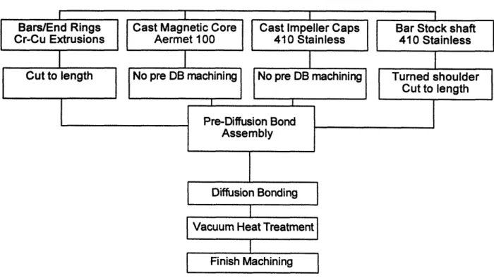
A flow chart of the process is shown in Figure 3.1.
Proposed Process for Induction Rotor Manufacture Bars/End Rings
Cr-Cu Extrusions
Figure 3.1. Final new production sequence for the high-performance induction rotor
The top row indicates the material, process, and initial form of each functional element of the rotor. Net shape processes are used to manufacture each element. They require minimal machining before assembly. Since the tolerances of parts produced by net shape processes are
generally higher than those of machined parts, the elements initially form a loose assembly. Final joining is accomplished through the diffusion bonding of the copper bars/end rings and impeller caps to the cast magnetic core using an electroless nickel interlayer. The entire assembly is then heat treated to optimize the electrical, magnetic, and mechanical properties of each material. Thus only one heat treat operation is used for the whole assembly, rather than for each part separately. Finally, the outer diameters (OD) of the rotor and shaft are ground to fit the stator and bearings.
3.3 Functional Decomposition
Functional decomposition of a part or an assembly separates the assembly into groups of parts with the same function. The function of each part is identified in the simplest terms possible for two primary reasons; they are to ensure that:
* unnecessary duplications of functions are eliminated, and
* parts do not contain features or have properties that add cost and do not relate to their function.
First, the function of the assembly as a whole must be stated (the starter/generator rotor assembly is shown in Figure 3.2). The function of the rotor is to produce mechanical power by the conversion of electrical energy.
Figure 3.2. Exploded view of the rotor assembly
The rotor can be seen as the assembly of four components (Figure 3.2): the magnetic core, the conducting squirrel cage, the cooling mechanism (in this case, impellers at either face of the rotor), and the shaft. The function of each component is:
* cage -carries current induced by the stator to produce torque,
* core -transmits torque from the cage to the shaft, enhances torque produced by the cage (by increasing the magnetic flux density through the current loops),
* shaft -transmits torque from the core to outside the machine, and
* impellers -dissipates heat generated by losses in the conversion of electric to mechanical energy
A few design issues are immediately identified by the functional decomposition. The first is that there is a duplication of a function. The core transmits torque from the cage to the
shaft and the shaft transmits torque from the core to outside the machine. This suggests that the core and the shaft should be manufactured integrally, as one piece. This possibility will be examined in the section focusing on core fabrication. It is, however, important that this issue was identified by the functional decomposition. That is precisely its purpose.
Another point to notice is that the decomposition reveals that the core merely needs to suspend the cage in the magnetic field. Usually this is done by geometrically constraining the bars using holes in the core. This is not the only solution, however. Other methods ofjoining the cage to the core should and will be considered.
Finally, the decomposition shows that the cage should not be made to bear anything but inertial loads. The core should be the torque-transmitting member.
The following five sections will demonstrate the details of how the fabrication process for each functional element was determined. A similar analytical process will be carried out for each
element. First, the performance requirements of each element will be explained. These are obtained from the functions of each element and translated into engineering specifications. Second, the assembly requirements will be enumerated. This explains how the part needs to fit into the entire assembly. Both the performance and the assembly requirements are listed
explicitly as guidelines to which the manufacturing and joining processes must conform. Finally, the various manufacturing process possibilities will be listed and discussed. An optimum
3.4 The Magnetic Core
3.4.1 Performance and Assembly Requirements
As was seen in the functional decomposition, the function of the magnetic core is to suspend the cage in the magnetic field, enhance the magnetic flux through the cage bars, and transmit torque. The primary material properties required of the core are therefore mechanical and magnetic. To be more specific, the mechanical properties required are primarily high yield strength and high stress-rupture strength. Stress-rupture strength is the applied stress necessary to cause rupture in a specified time, usually 1,000 hours or 100,000 hours [1]. Magnetic
properties necessary for successful operation are high saturation induction, high permeability, high electrical resistivity, and low AC (alternating current) core loss. Saturation induction is the highest magnetic flux density possible in a material, when all the magnetic moments in the material are aligned with the applied field. Permeability is the ratio of the magnetic flux density obtained for a given applied magnetic field. It is roughly linear until saturation is reached.
The assembly requirements for the core are two-fold: the cage must be held to the core and the core must also be held to the shaft.
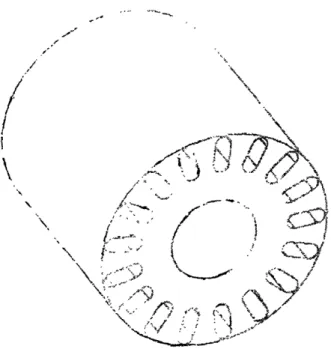
Two cores are shown in Figures 3.3 and 3.4. One is the starter/generator core and the other, more unusual, configuration is that of the traction motor (a photograph of which was given in Figure 1.1). The original starter/generator core was a laminated Co-Fe stack. The laminations are not pictured here for clarity.
/
/t
t'
I
Figure 3.3. Starter/Generator motor magnetic core
3.4.2 Materials Possibilities
In contrast to a conventional induction motor, the limiting material property that almost by itself dictates core material choice for a high speed machine is mechanical strength. The maximum stress in a spinning cylinder is the tangential stress (hoop stress) on the inner diameter generated by inertial forces. This maximum stress is [2]:
max 2
(3 + v)
(1-
)
(3.1)
'
4
(L
+
(3 +
G)
(Owhere p is the material density, v is Poisson's ratio, v is the tip speed and ri and ro are the inner
and outer radius, respectively. Since density and Poisson's ratio are quite similar (within 10% of each other) for most materials considered, the dominant term in Equation 3.1 is the tip speed. The ratio of inner to outer radius has little effect unless the rotor has no interior hole (e.g., an integral shaft/core) in which case the maximum stress is decreased by a factor of two [2]. For example, the tip speed of the high speed alternator, which has a diameter of 66 mm and runs at a design speed of 100,000 rpm, is 345 m/s. The stress on the inner diameter of the core is 1450 MPa.
The only magnetic alloys with the necessary strength are the cobalt-irons (for some of the lower tip speed applications) and Aermet. Not only are the cobalt-iron alloys five times as expensive as Aermet ($50/lb compared to $10/lb for Aermet, based on a quote from Carpenter Technology Corporation), but they are only available in sheet and are difficult if not impossible to cast effectively due to segregation of phases during cooling. An additional problem with the
Co-Fe alloys is that their magnetic properties are severely damaged at temperatures above 870 *C [3]. This limits manufacturing and processing options.
3.4.3 Design for Net-Shape Fabrication: The Solid Rotor with Open Slots
The main issue to be dealt with regarding the form of the magnetic core is the necessity of using a solid, rather than laminated, core. While cores are laminated to reduce eddy current losses and improve the performance of low tip speed machines, stresses in high tip speed rotors are too high for a laminated core. It seems the use of a solid rotor is unavoidable for high stress applications. For a solid rotor, the eddy currents induced by the field on the rotor surface will increase, degrading the efficiency of the machine. Since some axial currents will be induced in the rotor, torque will increase at a given speed. Efficiency, however, will decrease.
There are ways to minimize the increased losses. One way is to reduce the ripple in the field that the rotor encounters by closing the stator slots as much as possible [4]. Most
conventional stator slots are left wide open so that an automated winding machine can insert the stator windings. In SatCon's designs, however, the stator slots are largely closed.
In order to use any net-shape process effectively in this application, another geometry change must be made to the core. It will be necessary to "open" the slots of the core, making the cross section of the core look more like a gear. Figure 3.5 shows the cross-sectional change. This is done for two reasons. The first is that it would be very difficult to cast the thin walls around the exterior of the slots, typical dimensions of which are shown in Figure 3.6. Unless such a rotor were gated at the wall of every slot, which might require the gating of upwards of 30 slots, some slots would have voids due to premature freezing. Second, if a casting process were
used, closed slots (i.e., holes in the core rather than grooves in the surface) would require the
insertion of cores in the mold. For the starter-generator rotor, as an example, this would mean
the insertion of 17 cores in each mold. This would make the casting process excessively costly.
Figure 3.5. Cross section ofthe original core (left) contrasted with that of an open slot core
(right)
i C002000
R
1.645
-.
000
l
.o002
JA
085
+.000
-.
002
34X
R
FULL
Figure 3.6. Typical wall dimensions of a closed slot core (starter/generator geometry)
17X
11 7"\11 . * 1", ý "•
The effect of open slots on motor performance must now be analyzed
electromagnetically. The quantitative effect was calculated using the mathematical model embodied in the Matlab code described in Chapter One [5].
There are two competing phenomena in operation with respect to the opening of the slots: one which tends to improve performance (i.e., efficiency) as the slots are opened and one which tends to degrade it. The first is the decrease of leakage flux, expressed by a decrease in the leakage inductance of the rotor as shown in Equation 1.7. A decrease in leakage inductance results in an increase in total rotor inductance. If rotor inductance is higher, rotor current is higher for a given stator flux, as shown by Equation 1.6, and therefore developed power is higher according to Equation 1.9.
The second effect is flux concentration due to the presence of less iron. This latter effect is usually expressed as a larger equivalent air gap, which decreases the air gap permeance, g ag from Equation 1.8. A decrease in air gap permeance results in a decrease in rotor inductance,
hence decreasing the current induced on the rotor, hence decreasing power.
Leakage flux is a magnetic flux that does not couple the rotor and the stator windings and therefore does not assist in the conversion or production of power [6]. Ideally, the path of least magnetic resistance (called the lowest reluctance path), is across the motor's air gap and through
the current loops in both the rotor and stator. Figure 3.7 illustrates the mechanism of leakage. For a closed rotor slot (left), some of the flux produced by current in the rotor can go through the iron (a low reluctance path until the iron is saturated). This flux does not cross the air gap and couple to the stator, but it still requires power (i.e., rotor current) to create. For the open slot
(right) the lack of iron increases the reluctance of that path, reducing the amount of flux through it. More flux therefore crosses the gap and produces power.
age Flux
Slot
Rotor
Slot
SLeakage
Stator
Coupling
[Power
Producing)
Flux
Rotor
Figure 3.7. An illustration of the concept of leakage flux in an electric machine
The leakage inductance L, is proportional to the slot permeance, P,1sot, which is given by
[7]:
(3.2) ioslot :Ao{ 2 s
where I is the rotor length and hd,wd,hg, and wg are defined by the slot model geometry in Figure 3.8. For an open slot, hd=O so the slot permeance is reduced.
WA
Figure 3.8. Slot model geometry (after [7])
Figure 3.9 illustrates the effect of flux concentration. When slots are closed, the flux can distribute itself uniformly across the air gap and be essentially radial. With open slots, the flux becomes concentrated in the teeth between successive conductors (conductors are not
ferromagnetic and therefore are a high reluctance path for flux). The fringing has several
negative effects: the iron gets closer to becoming saturated, increasing the reluctance of the path across the gap; the fringing creates components of B in the circumferential direction which are useless for creating torque; and leakage on the stator side of the gap is increased.
HRC(
I
I
I
I
a) Closed Slots
b) Open Slots
Flux Uniformly Distributed
Flux Concentrated
Mostly in Teeth
Figure 3.10. Flux concentration due to open slots (after [6])
The increased reluctance of the air gap is expressed as an increase in the effective length of the air gap by an empirically derived coefficient. The reluctance of any flux path is the reciprocal of the permeance and is given by a formula similar to that of electrical resistance:
L
Rm (3.3)
where L is the length of the path, A is its cross-sectional area and gt is its permeability.
In order to determine how these effects play out quantitatively, a numerical experiment was carried out using the Matlab code with the geometry of the (closed-slot) starter-generator. The geometry of the slot is modeled as was shown in Figure 3.8. To model an open slot, hd was set to zero and wd was set equal to ws.
To run a comparison with the closed slot results, the total cross sectional area of the bars remained the same as the height and width were varied. Tooth flux density (i.e., the flux density
in the iron around the slots) as a function of slot width is shown in Figure 3.10. The code
calculates flux density from geometry (inductances), stator currents and an average permeability of the rotor iron. In reality, however, the permeability of a ferromagnetic material drops off to
2.5 2 -, IO = 5 ,€,. ©~ b--(• 3 4 5 6 7 8 9 10 11 12 x 103
Slot width (meters)
Figure 3.10. Tooth flux density vs. slot width for open-slot starter/generator rotor. The tooth iron is taken to saturate at 2 Tesla. The highest feasible slot width is thus about 9.5mm, as shown.
n C0oA
0.982
I I 11 1
Slot width (meters) x 10.3
Figure 3.11. Efficiency vs. slot width for the open-slot starter/generator rotor
o 1 0 t-C 0 0
0
A 2`---~-·--7----~_--i----T----?--_T-.-H I -i I 0.75 0.7 0.65 o 0..6 0.55 0.5 n045; I . i 1II I II 3 4 5 6 7 8 9 10 11 12
x 10
Slot width (meters)
Figure 3.12. Power factor vs. slot width for open-slot starter/generator
nearly zero when the iron is saturated. As the slots become too wide (to the right of the plot), the
teeth become too small and the iron is saturated at a flux density of about 2 Tesla. The slot width
at which the flux density is equal to 2 Tesla is therefore the useful limit of the results. The
effects on efficiency and power factor (an expression of the difference in phase between output
voltage and current giving real power output) for the variances in slot width are shown in Figures
3.11 and 3.12. The efficiency and power factor of the original configuration were 98.2% and
75.3%, respectively.
It can be seen that the effect of opening slots is a second order effect. In the useful range
of the plot (i.e., before the tooth iron saturates) efficiency varies by about 0.3% and power factor
varies about 8%. As the conductors become too thin (on the left of the plot), leakage decreases
while the increase in effective air gap increases faster, thus degrading performance. There is an
optimum open slot width which is fairly close to the width of the original slots (about 8mm).
3.4.4 Net-Shape Fabrication Options
It seems, therefore, that the best option in terms of best performance at lowest cost is a
solid Aermet rotor. The issue now becomes how to form it. Briefly, the options to be considered
are: casting (investment, sand, or centrifugal), machining, powder metallurgy, forging, or
extrusion. Powder metallurgy (PM) and extrusion can be ruled out immediately for similar
reasons. Aermet is too strong and the cross-sectional area of the rotor too large to be extruded
cost-effectively, if at all. The press capacity required would be enormous. Aermet itself has never been extruded. It is similar, however, to some stainless steels in terms of composition and heat treatment so some comparisons can be made. In order to soften stainless steels for
successful extrusion, most are heated to 8150C or above [8]. Due to the sensitivity of Aermet's properties to the presence of impurities [9], these temperatures would require the extrusion to be carried out in an inert atmosphere furnace, further adding to cost. In addition, the directionality inherent in the grain structure of an extruded product would adversely affect the magnetic properties of an extruded Aermet core by introducing axial anisotropy [10].
The cross-sectional area of the rotor is too large to compact the powder of a sintered product without a tremendous press capacity. An additional consideration for powder metallurgy is the length of the core. The length (upward of 150 mm for some rotors) would lead to density and other property gradients in the final product [I1 ].
Several of the listed processes can be ruled out for other reasons. The core has a constant cross section, which would seem to make it ideal for centrifugal casting. Aermet, however, owes its good properties to tight control of impurities which requires the material to be vacuum cast. Although centrifugal vacuum casting should be possible in principle, it cannot be done with currently available equipment.
Figure 3.13. Integral shaft/core using representative dimensions (British units) from the starter/generator
The other issue, raised by the functional decomposition, is whether the core and shaft be constructed as an integral piece as in Figure 3.13. For the investment and sand casting processes the cost of the process is related directly to the largest dimension of the mold or die. In
investment casting, for instance, each wax mold must fit onto the sprue. The more molds that can be fit on the sprue, the more cost-effective the process is. Since the shaft increases the length of the mold by about a factor of two, fewer molds can fit on the sprue, diminishing the
effectiveness of the process. A similar argument can be made for the other processes. Since the shaft is such a simple geometry and can be bought from stock, it makes no sense to increase the size of the mold so dramatically to make such a simple piece. Thus, using a net-shape process to manufacture an integral shaft/core would be counter-productive.
3.4.5 Core Manufacturing: Conclusions
For strength reasons, a solid Aermet core must be used. The most cost-effective manufacturing process for this will be an investment, sand, ceramic, or resin mold casting process. For any of these processes, it is best not to cast an integral shaft/core. It will be
necessary to open the slots in the core to use a casting process effectively. This has been shown to have a second-order positive effect on performance. Open slots will, however, create an assembly problem with the cage, since the bars will no longer be geometrically constrained. This problem will be addressed with diffusion bonding in Section 3.8.
3.5 The Squirrel Cage
3.5.1 Performance and Assembly Requirements
The squirrel cage is an efficient shape for providing several conducting loops through which a changing magnetic field passes to produce a current. Loops on SatCon's motors range from 17 to 48 copper conducting bars. Since their primary function is to conduct electricity, their most important material property is electrical conductivity, which should be as high as possible. The highest grades of aluminum that are conventionally used in induction machines have conductivities of only 58% IACS at room temperature. High performance applications would require at least a conductivity of around 80% IACS. This conductivity must not fall off
precipitously when raised to the operating temperature of the motor, the upper limit of which is about 200 °C.
Also important in high speed applications is mechanical strength. Finite element analysis of a typical squirrel cage rotating at high speeds (50,000 rpm with an OD of 76mm for the