HAL Id: hal-02072144
https://hal.archives-ouvertes.fr/hal-02072144
Submitted on 18 Mar 2019
HAL is a multi-disciplinary open access
archive for the deposit and dissemination of sci-entific research documents, whether they are pub-lished or not. The documents may come from teaching and research institutions in France or abroad, or from public or private research centers.
L’archive ouverte pluridisciplinaire HAL, est destinée au dépôt et à la diffusion de documents scientifiques de niveau recherche, publiés ou non, émanant des établissements d’enseignement et de recherche français ou étrangers, des laboratoires publics ou privés.
Production and Patterning of Liquid Phase-Exfoliated
2D Sheets for Applications in Optoelectronics
Samanta Witomska, Tim Leydecker, Artur Ciesielski, Paolo Samorì
To cite this version:
Samanta Witomska, Tim Leydecker, Artur Ciesielski, Paolo Samorì. Production and Patterning of Liquid Phase-Exfoliated 2D Sheets for Applications in Optoelectronics. Advanced Functional Materi-als, Wiley, In press, pp.1901126. �10.1002/adfm.201901126�. �hal-02072144�
1 DOI: 10.1002/ ((please add manuscript number))
Article type: ((Review))
Production and patterning of liquid-phase exfoliated 2D sheets for applications in opto-electronics
Samanta Witomska, Tim Leydecker, Artur Ciesielski,* Paolo Samorì*
S. Witomska, Dr. T. Leydecker, Dr. A. Ciesielski, Prof. P. Samorì Université de Strasbourg, CNRS, ISIS,
8 alleé Gaspard Monge, 67000 Strasbourg, France E-mail: [email protected], [email protected] S. Witomska, Dr. A. Ciesielski,
Center for Advanced Technologies, Adam Mickiewicz University Umultowska 89c, 61614 Poznań, Poland
S. Witomska,
Faculty of Chemistry, Adam Mickiewicz University Umultowska 89b, 61614 Poznań, Poland
2
Abstract
Two-dimensional (2D) materials (2DMs), which can be produced by exfoliating bulk crystals of layered materials, display unique optical and electrical properties making them attractive components for a wide range of technological applications. In this context, attaining a full control over the generation of high-quality 2DMs with methods that can be employed for large-scale production of exfoliated nanosheets and inks thereof represents a major challenge of potential technological interest in the numerous fields, even beyond opto-electronics and sensing, such as those associated to energy applications. This Review describes the most recent developments in the production of high-quality 2DMs based inks using liquid-phase exfoliation (LPE), combined with the patterning approaches, highlighting convenient and effective methods for generating materials and films with controlled thicknesses down to the atomic scale. Different processing strategies which can be employed to deposit the produced inks as patterns and functional thin-films are introduced, by focussing on those that can be easily translated to the industrial scale such as coating, spraying and various printing technologies. By providing insight into the multiscale analyses of numerous physical and chemical properties of these functional films and patterns, with a specific focus on their extraordinary electronic characteristics, this Review offers the readers crucial information for a profound understanding of the fundamental properties of these patterned surfaces as the millstone towards the generation of novel multifunctional devices. Finally, we discuss the challenges and opportunities associated to the 2DMs’ integration into working opto-electronic (nano)devices.
3
1. Introduction
The cutting-edge results by Geim and Novoselov on the extraordinary physical properties possessed by graphene, has seeded and catalysed a tremendous effort on the development of new protocols to controllably exfoliate single layers (SLs) of other two-dimensional (2D) materials starting from their multi-layered bulk analogues. In parallel, such unique properties have also triggered immense research endeavours on the use of such materials for applications in numerous technological fields. In particular, 2D transition metal dichalcogenides (TMDs), such as SL of molybdenum (IV) disulfide (MoS2), molybdenum (IV) diselenide (MoSe2),
tungsten (IV) disulfide (WS2), tungsten (IV) diselenide (WSe2), etc., black phosphorus (BP)
or hexagonal boron nitride (h-BN) and have emerged in the last years as complementary materials to graphene and are being extensively explored as potential components in the next-generation flexible (opto-)electronic devices.
Graphene is an attractive 2D nanomaterial which has revolutionized the field of nanoscience and nanotechnology due its high thermal conductivity (5000 W m-1 K-1)[1] and high optical
transmittance reaching 98%,[2] large (theoretical) specific surface area (2630 m2 g-1)[3] and
outstanding mechanical strength and flexibility (Young’s modulus ~ 1 TPa).[4] Alongside
graphene, other 2D materials are attracting more and more interest because of their exceptional chemical and physical properties along with their thermal stabilities. Among them, group-6 semiconducting TMDs, in their SL form, display a sizeable direct energy bandgap (1-3 eV), extremely high Ion/Ioff ratios reaching ~108 and field-effect mobilities
within the 10-100 cm2 V−1 s −1 range.[5] Conversely, h-BN was found to be an electrical
insulator (band gap of ~ 6 eV).[6] Additional, metal halides (such as PbI
2 and MgBr2), layered
metal oxide (such as MnO2, MoO3 and LaNb2O7), black phosphorus (BP) and also silicates
represent interesting alternative layered compounds exhibiting distinctive properties. Such diversity of properties renders 2D materials (2DMs) ideal components for a variety of
4
technological applications, which include thin film transistors,transparent and flexible electronics, memory devices,light-emitting diodes,solar cells, sensors,etc.
Since the physical and chemical properties of 2DMs are unique and strongly dependent on their thickness at the very atomic-scale,[7] establishing exfoliation or delamination processes
to produce extremely thin sheets from layered system is of paramount importance. The deposition of such sheets to generate films is also crucial towards their use as electrodes or active components in many applications in opto-electronics, energy storage and generation as well as functional composites/foams for sensing, mechanical reinforcement and gas/ion barriers.[8] Depending on the employed exfoliation method, the obtained materials can be
extremely defective or almost defect-free, which are critical factors for their integration in working devices. Hitherto, different methods have been employed to produce 2DMs, and each of them yields material with drastically different properties.
This Review briefly introduces the recent advancements in the generation of atomically thin 2D nanosheets by means of an extremely mild and easily up-scalable top-down approach, i.e. the liquid-phase exfoliation. We discuss the wide range of techniques that can be used
towards the deposition of the produced inks into space confined patterns or continuous thin-films. We examine aspects related to the structure vs. property relationship. In particular, we focus on the importance of reaching a fine control over the material’s properties through a detailed understanding over their structure on the nanometer- to sub-nanometer-scale and interconnectivity between deposited sheets. Achieving such a thorough control will make it possible to harness the electrical and optical properties of the 2D nanosheets, being a mandatory step towards the realization of commercial high-performance applications based on 2DMs.
5
2DMs can be produced by using either bottom-up or top-down production strategies.[9] The
use of bottom-up techniques, such as chemical vapour deposition (CVD)[9-10] and epitaxial
growth,[9, 11] makes it possible to generate high quality materials with small number of
defects, which makes them good candidates for applications in nanoelectronics. However, these substrate-based techniques suffer from the limited scale and expensive production. Conversely, the production of 2D materials by means of low-cost and up-scalable methods has been demonstrated by employing top-down techniques, which are based on the
mechanical cleavage of layered materials using exfoliation methods.
Numerous 2DMs exist in their bulk form as stacks of multi-layered architectures. They all share a common structural characteristic, i.e. their composing atoms are held together in-plane by strong covalent forces whereas their inter-plane interactions are much weaker, usually being of van der Waals type. Upon breaking these weak bonds two-dimensional
nanomaterials can be exfoliated into individual flakes or few-layered (FL) sheets.
Among various exfoliation techniques, liquid-phase exfoliation (LPE) is extremely appealing since it allows the production of highly-concentrated inks of 2DMs, which can be deposited on different substrates by means of printing or other methods, enabling large-area patterning. LPE process typically involves three steps: dispersion of layered material in a liquid media, exfoliation and purification, which is necessary to separate exfoliated from un-exfoliated flakes is usually carried out via ultracentrifugation.[7, 12] The successful exfoliation occurs by
overcoming the van der Waals (dispersive London type) interactions holding together adjacent layers. Immersion in a liquid represents one of the most effective method to reduce the strength of these attractive forces.[13] When a solid surface is immersed in a liquid medium
the interfacial tension is high, therefore the dispersibility of the solid in the liquid is poor. The suitable solvent balances the inter-sheet attractive forces and stabilizes the nanosheets against
6
aggregation. The solvents which turned out being suitable to disperse 2D sheets are those that minimize the interfacial tension [mN m−1] between the liquid and the 2D flakes.[12]
Given that the properties of 2D sheets strongly depend on their lateral and vertical sizes, it is important to note that liquid-dispersed sheets can be sorted by thickness and size, which is instrumental for the production of high-quality functional films.[10b] Interestingly, such an
approach is applicable to a widest range of layered materials.[14] This Review introduces the
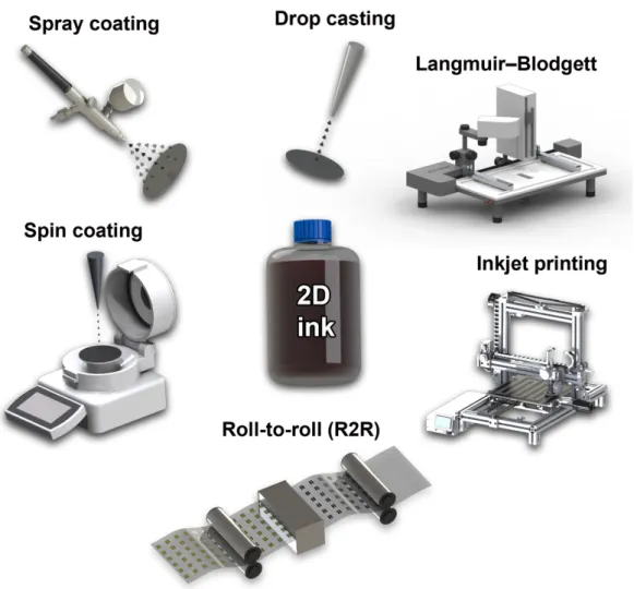
reader to the various LPE based methods such as ultrasound induced LPE (UILPE),[15]
electrochemical exfoliation (EE),[16] high-shear mixing exfoliation (HSE),[17]
solvothermal-assisted LPE (SALPE),[18] microfluidization[19] and ball-milling[20] (see Figure 1). The LPE
strategy is gaining attention because it represents a potentially up-scalable route for the mass-production of inks of a wide variety of 2D nanomaterials, yet not all LPE approaches can meet the requirements of industrial protocols. Significantly, it is extremely versatile, cost– effective and does not require specific substrate and production conditions (high vacuum and temperature) towards the 2DM integration in working devices.
The LPE approach can be assisted by the simultaneous chemical treatments of 2DMs with e.g.
n-butyllithium or inorganic acids to obtain colloidal stable suspensions.[21] Such a combined
approach render it possible to exfoliate other interesting classes of 2DMs such as graphene oxide (GO) or 2D carbides and nitrides (MXenes).[22] However, the use of such chemical
treatment is beyond the focus of this Review article, therefore it is not included below.
2.1 Characterization method
Both qualitative and quantitative information are required in order to thoroughly characterize the materials exfoliated via LPE methods. In particular, spectroscopic and microscopic characterizations of exfoliated 2DMs are vital to determine exfoliation yields and full understanding of the overall 2DMs’ properties as well as the morphology of the exfoliated
7
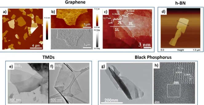
flakes (size, shape and thickness). Nowadays, there are a vast number of characterization techniques that can be utilized to investigate 2DMs’ properties in a fast and non-destructive manner. Noteworthy, most of these techniques can be used in laboratories and at mass-production sites. The lateral size, morphology, shape and thickness of the 2D nanosheets are usually determined via microscopic characterization by high-resolution transmission electron microscopy (HR-TEM) and atomic force microscopy (AFM) (see examples in Fig. 2). While the former allows the estimation of the number of layers of exfoliated (NL) sheets by counting
the number of sheet’s edges and by using electron diffraction patterns,[23] the latter enables the
estimation of NL by measuring the height of the flakes and dividing it by the corresponding
interlayer distance.[24] Yet, it is important to note that estimation of SL flakes height via AFM
varies with the nature of the substrate (e.g. roughness, hydrophobicity or hydrophilicity) and depends on the magnitude of the force applied by the tip to the sample as well as the
experimental conditions such as relative humidity.[25] Nevertheless, AFM can be employed to
gain in-depth insight into the surface morphology of exfoliated flakes of 2DMs, as shown in Fig. 2a and 2d for graphene and h-BN, respectively. Moreover, AFM can reveal the presence of structural defects on the surface of SL graphene flake (Fig. 2b).[25]
Recently, Backes et al.[29] introduced photoluminescence excitation spectroscopy as a mean to
identify the NL in MoS2 and other TMDs[30] as well as BP.[31] Another widely utilized
spectroscopic technique is Raman spectroscopy,[32] which is commonly used to examine
whether the exfoliated material is structurally similar to the bulk material and more importantly how much defects (if any) are introduced during LPE process. Raman
spectroscopy is also a powerful tool to identify unwanted by-products, structural damage and doping of 2DMs. It has been a key experimental technique to study the bonding nature of graphene[33] or MoS
2.[34] The main features in the Raman spectra of graphitic carbon-based
8
of the D peak, called 2D peak, appears around 2680 cm–1, and its shift and shape has been
correlated with the number of graphene layers (Fig. 3).[23a, 36] Furthermore, the intensity ratio
ID/IG is commonly used to quantify the disorder level in graphene.[37] After a certain degree of
disorder the addition of defects lead to an attenuation of the peaks, and consequently, to a decrease of the ID/IG ratio. Raman spectroscopy shows also its potential for different types of
2D layered materials.[38] The anomalous frequency trends for E1
2g and A1g modes for MoS2
and WS2 can be used for layer thickness determination for 1-5 layers MoS2/WS2 (Fig. 3).[38a, 38c] Nevertheless, it is not enough for 2D flakes with layer number greater than 5. Besides the
information on layer thickness of TMDs,[38c] Raman spectroscopy can provide details about
atomic coordination and crystal lattice, e.g. trigonal prismatic (2H) vs. octahedral (1T).[39]
Figure 3c presents also the Raman spectra of BP as a function of the number of atomic layers, from the SL to an optically thick bulk sample.[40] From bulk to atomically thin samples, slight
frequency variations and the appearance of two new Raman active vibrational modes located above A1g and A2g, were observed. It is important to note, that the Raman spectrum of 2DM’
sheets produced by LPE differs from the one of 2DMs produced by micromechanical exfoliation (MME) using the scotch tape approach.[41] This can be anticipated since during
LPE process, the material is strongly interacting with the solvent and as in the case of UILPE it is subjected to strong mechanical stress because of the collapse of bubbles and voids in the liquid, which results in the fragmentation of the flakes: overall the LPE may produce
significant changes in the Raman peaks, which could be related to structural changes, but also doping – caused by solvent residuals, and re-stacking of the exfoliated sheets.
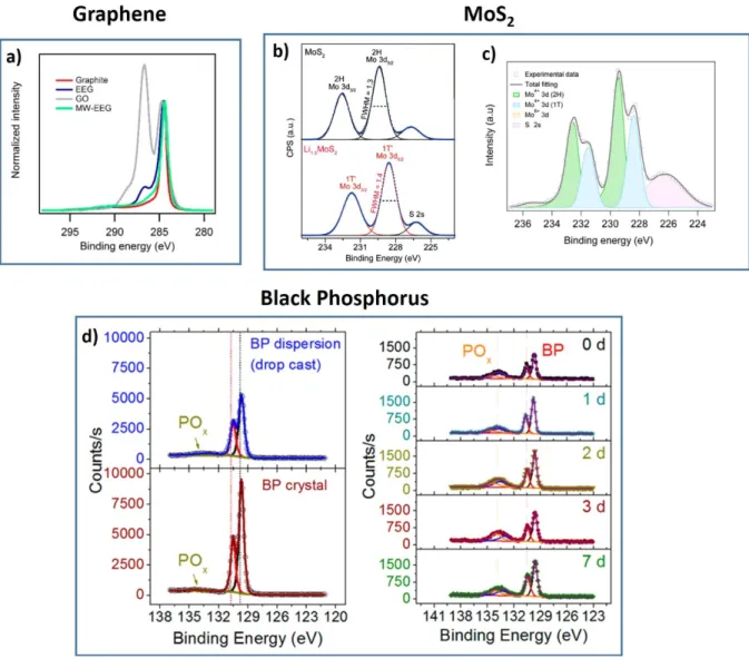
X-ray photoelectron spectroscopy (XPS) represents a powerful tool to analyse the chemical components and electronic states of the elements in the graphene and other 2DMs. Moreover, XPS analysis allows monitoring of chemical composition of the material as a function of LPE duration. Changes on the XPS spectrum of exfoliated graphene can be follow on the C1s
9
spectrum, as shown in Figure 4a.[25] Oxidation of the material during LPE is observed on the
C1s spectrum of graphene, compare to pristine graphite (Fig. 4a). Moreover, the content of oxygen, and consequently the C/O ratio determined by XPS can be used for comparing samples of different research groups. XPS spectroscopy can also be employed to evaluate the composition of 1T and 2H phases for the TMDs like MoS2 (Fig.4b-c).[16b, 42] Kang et al.[43]
presented spectroscopic analysis of BP nanosheets using XPS, as shown in Fig. 4. Small oxidized phosphorus (i.e., POx) bands are also apparent on the XPS spectra (Fig. 4d).Oxygen
defect are introduced during solvent exfoliation. Additionally, Figure 4d reveals that, despite 1, 2, 3, and 7 days of ambient exposure the BP nanosheets, the POx content are similar,
indicating slowed ambient degradation of BP nanosheets obtained by LPE, compare to mechanical exfoliation.[44]
The current state-of-the-art on the successful LPE procedures by providing a quantitative description and mechanism of the most relevant production procedures exploited to exfoliate high-quality 2D materials are detailed below.
2.2. Ultrasound induced liquid phase exfoliation (UILPE)
Ultrasounds induced liquid-phase exfoliation (UILPE) process is one among the most straightforward approaches for the production of homogeneous dispersions of 2DMs, being commonly exploited to exfoliate layers from bulk materials in liquid media. Noteworthy, the quality of 2D nanosheets produced by UILPE method is affected by the exfoliation medium (water or organic solvents), the experimental set-up (probe or bath sonication) and by the parameters (conditions) used for the exfoliation. The role played by the exfoliation medium, such as (organic) solvents, stabilizing agents as surfactant/water solutions, ionic liquid, salts and polymer solution etc., has been discussed in several up-to-date reviews.[12, 15b, 45] During
10
of the micrometer-sized bubbles or voids in liquids due to pressure fluctuations, act on the bulk material breaking up the layered structure and induce exfoliation to produce SL or FL nanosheets.[13]
It is commonly accepted that the liquids with a surface tension of around 40 mJ m−2 are
applicable for the dispersing of graphene, graphitic flakes and TMDs.[46] However, majority
of nanosheets are obtained at room-temperature and short sonication time, and therefore it is important to note that if the temperature is increased, the surface tension will vary. A library of organic solvents was exploited in the pioneering work of Coleman’s group in 2008,[23b] and
only a few solvents have been selected and are being used worldwide as optimal UILPE media. These include N,N-dimethylformamide (DMF) and N-methyl-2- pyrrolidone (NMP)
ortho-dichlorobenzene (o-DCB). In particular, dispersion of SL and FL graphene nanosheets
have been obtained in NMP at concentrations of up to 0.01 mg mL−1. However, such a
concentration is far too low to meet the industrial demands and find practical application. Undoubtedly, the selection of ultrasonication parameters such as time and power plays an important role during the UILPE and there are extensively investigated to increase the yield of the exfoliation process. In the past, we examined the effect of the ultrasonication power in both NMP or o-DCB.[15a] Towards this end, we have carried out the UILPE at 600 W and
1000 W. The analysis of independent UILPE experiments revealed that when UILPE is performed at 600 W, comparable values of exfoliation yields, and in particular the
concentration of obtained dispersions in NMP and o-DCB are obtained. It was concluded that the exfoliation yield of NMP-based dispersions does not depend on the power of the
ultrasonic bath, while the concentration of dispersions obtained from o-DCB decreased drastically. These results highlight the importance of the choice of the UILPE solvents. Moreover, the power of ultrasonication can strongly influence on the lateral size of the exfoliated SL and FL nanosheets in o-DCB. In particular, when UILPE is carried out at 600
11
W, the dispersions have been found to be composed of graphene nanosheets with a lateral size of 180 nm, whereas at higher power (1000 W) graphene nanodots (GNDs) with an average width of ∼17 nm have been produced. While in the specific case the great difference in the lateral size of the exfoliated sheets can be ascribed to the sonication-induced activation of chemical processes such as radical formation in the o-DCB solvent molecules, which are highly reactive species that can strongly interact with the graphene flakes during the
exfoliation thereby determining their lateral size, other physical phenomena can be brought into play by varying the sonication power.
Numerous attempts have been made to increase the yields of the UILPE by exploring
parameters such as severely longer sonication (up to ca. 500 hrs).[47] Nevertheless, such
time-consuming method demands high energy input and results in the severely reduced size of the flakes.[48] In addition to the reduced size of the produced flakes, long sonication of graphite
can also affect the quality of the produced graphene. For short ultrasound treatments the exfoliated graphene displays defects predominantly at the edges of the graphene flakes whereas the basal plane of the flakes is defect free.[48] Yet, the prolonged sonication
significantly affects the morphology of the flakes. In particular, defect formation during cavitation was precisely monitored by Bracamone et al.[49] It was found that for short
sonication (30 min) defects are located mainly at the edges of the flakes, while they start appearing on the basal plane for sonication times exceeding two hours. In contrast to the common belief that UILPE is a non-destructive process,[23b, 45b, 47, 50] these results indicate the
existence of defects both in the basal plane and the edge. Therefore, a selection of appropriate conditions of UILPE, like solvents, sonication time or power, is highly recommended.
Another important drawback of UILPE, which ultimately hampers its use on the industrial scale is the fact that the majority of solvents employed for UILPE possess a high boiling point and are thus extremely tough to be removed after exfoliation. Because of this reason, the
12
deposition of 2DMs inks produced via UILPE onto plastic substrates is extremely challenging since thermal annealing at high temperatures is required to achieve the complete solvent removal.[51] In particular, the use of NMP as a prime solvent in 2DMs inks results in long
drying time and is impractical for the majority of printing technologies. A much better solution would be to exfoliate graphene in a low boiling point solvent such as ethanol,
isopropanol, chloroform, etc. However, they fail to meet the aforementioned characteristics of solvents required for the suitable 2DMs exfoliation. As the number of possible solvent
mixtures is virtually unlimited, the strategy based on mixed-solvent gives researchers great freedom in designing ideal solvent systems for each specific application. In this context, the library of low-toxic and low-cost solvents with low boiling points for UILPE is infinitely enlarged when extending to common co-solvents. However, the use of such approach supports only comparatively low concentration of 2DMs without stabilization of exfoliated 2D sheets.[52] Nonetheless, O’Neill et al.[50d] demonstrated the exfoliation of graphene at
concentration up to 0.5 mg mL−1 in low boiling point solvents such as chloroform and
isopropanol (IPA). Graphene flakes of the lateral size of ∼1 μm and with a thickness of less than 10 layers (≤5 layers for isopropanol) have been obtained. In addition, the deposition of graphene flakes into substrates by spray-coating was also investigated. Some aggregation during evaporation of volatile solvents was observed. However, the deposited flakes tend to assemble into features which are thinner than those obtained with flakes deposited with high boiling point solvents. Moreover, the substrate coverage is much greater when using more volatile solvents, predominantly due to faster evaporation.
On the other hand, in order to match the surface tension between solvent and 2DMs, one can add to the liquid either polymers,[12, 51] ionic and non-ionic surfactants,[50b, 50c, 53] ionic liquids
(ILs),[54] organic compounds[45a, 55] or inorganic salt.[56] In contrast to exfoliation in organic
13
flakes, providing electrostatic repulsion, which prevents reaggregation of 2D nanosheets and supports higher concentration of stabilized flakes in the liquid environment.[12, 15b] Coleman et
al. first proposed the exfoliation of graphene from graphite powder with a concentration of
0.1 mg mL−1 by UILPE in sodium dodecylbenzenesulfonate (SDBS) aqueous solution.[50b] It
was pointed out that SDBS cannot be easily removed and the films contained ∼35% SDBS surfactant. Moreover, it was found that the residual surfactants affect also optical and electrical properties of graphene films. In the case of non-ionic surfactants, which typically have a hydrophobic tail and a long hydrophilic part, steric repulsions stabilize exfoliated 2DMs.[57] One of the best effective non-ionic surfactant for the preparation of graphene
dispersions is triblock copolymer Pluronic P-123.[53] It has been demonstrated, that increase in
sonication time, from 2 to 5 hrs, significantly raised the concentration of stably dispersed graphene, from 0.9 to 1.5 mg mL−1.[53]
The polymer can also encapsulate the 2D flakes enabling a physical separation between the flakes to allow enhanced exfoliation and further stabilization. Furthermore, Li et al. [58]
presented one of the most interesting techniques to form inks for printed electronic.[59] The
authors prepared graphene dispersion for inkjet printing for electronics purposes. In particular, the procedure involves UILPE of graphene in DMP for 40 hrs followed by the addition of ethyl cellulose (EC) to obtain stable graphene dispersion. After being exchanged by terpineol through a vacuum distillation process, the graphene concentrations were
estimated to be 1.2 mg mL−1. Interestingly, Hyun et al.[60] showed that it is possible to obtain
the stable graphene dispersion in EC/ethanol/terpineol with concentration up to 80 mg mL−1.
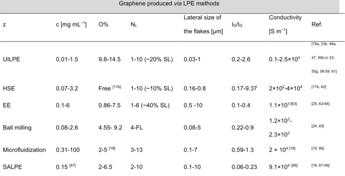
The quality of the exfoliated graphene and the conductivity values achieved in various LPE methods as presented in the recent literature are summarized in Table 1.
Coleman’s group was the first to extend UILPE towards other 2DMs beyond graphene.[70] It
14
for exfoliation of h-BN with concentration around 0.3 mg mL−1 and 0.15 mg mL−1 and 0.06
mg mL−1, respectively. TEM revealed the existence of 2D flakes consisting of thin nanosheets
(Fig.2. e-f). Moreover, it has been demonstrated that this process is also suitable for
exfoliation of other TMDs, such as NbSe2, TaSe2, MoSe2, MoTe2, NiTe2.[70] This exfoliation
method made it possible to prepare films of MoS2 and WS2 by vacuum filtration and spraying,
with thickness ranging from a few nanometers to hundreds of micrometers. Recently, Kelly et
al.[71] generated TMDs inks for thin-film transistors using UILPE. Towards this end, WSe2,
WS2, MoS2 and MoSe2 crystals have been sonicated in NMP and size selection has been
performed to isolate the thinnest nanosheets (˂ 6 layers). To obtain the printable inks the materials were redispersed in IPA with concentration ˂ 0.8 mg mL−1, using solvent-exchange
method. In further studies, Coleman’s group systematically investigated the role the experimental parameters during the UILPE of MoS2 in NMP including the starting mass,
sonication power, sonication time, and centrifugation conditions.[72] The dispersed
concentration of MoS2 increased to ∼40 mg mL−1 by increasing the sonication time to 200
hrs. The concentration of MoS2 nanosheets scales linearly with the starting MoS2 mass and
was maximized for an initial MoS2 concentration of 100 mg mL-1. However, the flakes
produced by long-time sonication exhibited small lateral size and broad size distribution as observed previously for graphene dispersions.[47] Furthermore, by controlling the
centrifugation process, large-size flakes can be obtained with mean flake lateral size of
approximately 2 μm and maximum lateral size of 4–5 μm. Smith et al.[73] exfoliated inorganic
layered compounds such as h-BN, TMDs (MoS2, WS2, MoTe2, MoSe2, NbSe2, TaSe2) in
aqueous surfactant solutions (sodium cholate/water mixture). Nonetheless, MoS2 exfoliated in
presence of surfactants yielded nanosheets with up to 10 stacked layers, indicating a low degree of exfoliation. Recently, Wang et al.[74] applied thermo-responsive polymeric ionic
15
aqueous medium. The concentration of exfoliated MoS2 and h-BN nanosheets in suspensions
was found to amount to 1.24 and 0.43 mg mL−1, respectively. Morishita et al.[75] achieved
highly concentrated boron nitride dispersions by direct exfoliation of bulk hexagonal boron nitrides using ionic liquids (ILs). In particular, 1-butyl-3-methylimidazolium
hexafluorophosphate [bmim][PF6] afforded a highly stable h-BN suspension at concentration
(1.9 mg mL–1) containing less than 10 layers. Therefore, the cation–π interactions between
[bmim][PF6] and h-BN surface N atoms play the most important role in the h-BN exfoliation,
even more important than the matching of their surface energies.
The UILPE approach has been also successfully extended to BP, by using NMP as solvent to produce BP nanosheet dispersion.[43, 76] Additionally, other high boiling point solvents[31, 77] as
well as water[78] or acetone[79] were utilized for UILPE of BP. Recently, Hanlon et al.[31]
reported UILPE of BP under ambient conditions in solvents such as N-cyclohexyl-2-pyrrolidone (CHP), which stabilizes the BP nanosheets against oxidation, probably due to protection by the solvation shell. However, production of high-quality BP flakes inevitably leads to the formation of small sized flakes ~ 1 μm2. Concentrations as high as ~ 1 mg mL−1
can be realized during prolonged sonication (100 hrs). Chen et al.[28] prepared water
dispersion of FL BP nanosheets with 0.4 mg mL−1 concentration, which corresponds to a yield
of 6.7 wt%. HR-TEM images revealed the presence of good quality nanosheets with orthogonally symmetric structure, without visible impurities or defects (Fig. 2g-h). They suggest that the high stability of BP sheets can be attributed to their intrinsic high crystallinity and high purity, as well as the oxygen-isolated measurement conditions. The results indicated that this BP dispersion is stable enough for further processing, when it is stored in oxygen-isolated containers.
It is well known that, some of the extraordinary properties of 2D nanomaterials, such as the electronic bandgap, are strongly layer dependent, especially at their atomically thin limit.[7]
16
The broad size distribution of 2DMs produced by UILPE is one of the main limitation for their application. Moreover, the yield of the SL nanosheets in the exfoliation suspension is low and the lateral size of the produced nanosheets is relatively small because the sonication force breaks down the big nanosheets into small fragments. Furthermore, there are also some disadvantages in using intercalants/stabilizers to assist the UILPE process of 2D nanosheets. The preferable liquid medium for the electronic application is a pure solvent as this does not introduces impurities into the exfoliated 2DMs. Regardless of whether the 2D films are prepared by deposition techniques like drop-casting or spraying, in most of the cases, the resulting films still comprise surfactants, which do not possess any appealing electronic properties; in other words, their presence can be problematic for applications in electronics. A definite downside is that polymers cannot be easily removed from the 2DMs’ surface after the exfoliation. However, it should be pointed out that the presence of polymers can also be highly beneficial. Polymer adsorbed onto the material surface after exfoliation can allow the tuning of the physical properties of the ink, which can be desirable for printing electronics as they can affect the properties of devices, e.g. by n-doping of 2D materials-based devices.[80]
Semiconducting polymers can also be added before or during the LPE as demonstrated in a recent report on the production of hybrid graphene/semiconducting polymer films. These hybrid films have proven superior field-effect mobility (as compared to the bare organic semiconductor) and improved processability (as compared to the pure 2D ink).[81]
Table 2 and Table 3 list the key variables describing the electronic properties of 2D materials
beyond graphene.
2.3. High-sheer mixing exfoliation (HSE)
Although UILPE achieves ultrathin 2D nanosheets with concentrations up to ∼1 mg mL−1,
17
the step forward from the laboratory to industrial scale production, it is imperative to develop scalable methods to produce large quantities of 2DMs at low-cost and relatively short time. Towards this end, Paton et al.[17b] and Liu et al.[86] demonstrated shear force-assisted
liquid-phase exfoliation (HSE) for producing dispersions of graphene flakes (Fig. 5). In this method, the high-shear mixer consisting of rotor and stator (or rotating blades) was used to generate high shear rates in liquids, to which the layered powders were added. The working
mechanisms of the high shear mixer are based on hydrodynamics and can be divided into high shear force, collision effects and jet cavitation.[87] In a high-shear mixer, very high shear rates
are achieved in the gap between the rotor and stator and in the holes in the stator. It has been concluded that the graphene exfoliation process is most likely localised in the vicinity of the rotor–stator.[17b, 88]
The Coleman’s group developed a simple model that shows the occurrence of exfoliation once the local shear rate exceeds a critical value that was found being ~ 104 s −1.[17b] This
allowed graphene to be efficiently exfoliated in NMP up to the hundred-litre scale with production rates exceeding 5.3 g hrs−1 in 10 m3 yet the concentrations of graphene are
relatively low, being ca. 0.07 mg mL−1. Although the HSE allows producing large quantities
of inks, the quality of exfoliated material is not extraordinary. In particular, the thickness distribution (1-10 layers) and the lateral size of the flakes (200-800 nm) suggest that the fragmentation of the flakes occurs much faster than the exfoliation. Importantly, the production rates can indeed be enhanced by increasing the volume, which is an ideal case scenario for scale-up. Interestingly, Liu et al.[86] showed the green alternative to HSE by using
IPA-water mixture to exfoliate graphene. The concentration of the graphene dispersion prepared in 40 vol% IPA-water mixture is about 0.27 mg mL−1 which is far greater than that
18
important parameters in hydrodynamics and can influence the motion of the liquid layer. Consequently, the best experimental volume fraction was proposed as 40 vol% IPA-water for preparing graphene nanosheets via the HSE. Electronic properties and quality of high shear exfoliated graphene are presented in Table 1, Section 2.1.
It is not surprising that HSE approach on a number of layered crystals beyond graphene, such as TMDs and h-BN has already been demonstrated (see Table 2. Section 2.1).[17] HSE route
was also extended to exfoliate BP bulk crystal into FL nanosheets.[84] After 9 hours 0.04 mg
mL−1 suspension was obtained. In this dispersion, nearly 25% of the sample was SL and the
lateral size was similar to the material produced using bath sonication at a smaller scale. All the aforementioned results indicate that HSE is a promising new technology for large scale production of 2DMs that can be processed by using existing industrial technique, such as real-to-real manufacturing.[17b, 89] Industrial rotating blade stirrer tank reactor can be used
for LPE offering a low cost alternative to sonication, in view of the exfoliation efficiency, which is much higher than that in standard sonication or ball milling exfoliation methods. The main advantage of HSE is its simplicity and production of high quality with few defects 2DMs. Nevertheless, HSE provides nanosheet at relatively low concentrations (<0.1 mg mL−1), limiting the efficiency of the process. If high concentrations are required, then better
results will be achieved by sonicating at high energy density. However, if high production rate is needed, shear mixing seems to be the only possible solution.
2.4. Electrochemical exfoliation (EE)
Electrochemical approaches are becoming more and more popular towards exfoliation of 2DMs and it have drawn increasing attention over the past years as a potentially scalable method. Among them, electrochemical exfoliation (EE) of graphite in both aqueous and organic electrolytes is extensively explored as it can be used to produce graphene flakes of
19
different sizes, thicknesses, and quality. The basic concept of EE relies on the use of
intercalating ionic species, which penetrates into bulk 2DMs under an electrochemical bias to drive structural expansion at a graphite electrode.[90] EE of graphite into graphene - commonly
referred to as electrochemically exfoliated graphene (EEG) - can occur either under anodic or cathodic conditions.[16a] While the anodic exfoliation process can be carried out in the mixture
of water and ionic liquids,[91] aqueous solution of inorganic salts or mineral acids,[64a, 64b, 90b, 92]
the cathodic method relies on the use of organic solvents (e.g., propylene carbonate (PC),[93]
dimethyl sulfoxide (DMSO),[94] NMP,[95] acetonitrile[96]) containing lithium or
alkylammonium salts.
In the anodic process, the potentials required for the anions to intercalate are usually greater than the potentials needed for graphite oxidation,[16a] thus anodically exfoliated graphene tend
to be significantly oxidized due to the generation of reactive oxygen species from water at the graphite anode. While it is not desirable for the electronic applications, in general extensive oxidation should be avoided.[25] In EE, both the exfoliation time and the type of employed
electrolyte can led to the formation of defect-free graphene sheets at high concentrations.[97]
To address this issue, researchers have explored some approaches to hamper the oxidation process, e.g. by using specific types of graphite as the anode[98] or inorganic salts instead of
acids as the electrolyte,[25, 64b, 99] multifunctional electrolytes[97] and also by performing EE in
confined space.[64d] In anodic process, Liu et al.[100] exfoliated graphite rod using protonic
acids like H2SO4, H3PO4 and H2C2O4 in the voltage range of 6-8 V. Among these various
inorganic acids, sulfuric acid attracts the attention in exfoliation of graphite because the ionic size of SO42– (0.46 nm)is similar to the graphite interlayer spacing (0.34 nm), which is
favourable for the intercalation process.[101] Moreover, electrolysis of sulfate ions and water
can lead to the generation of gaseous species such as oxygen, hydrogen and sulfur dioxide and cause the expansion of the interlayer distance of graphite. Su et al.[92b] also examined a library
20
of different electrolyte for the EE of graphite, including HBr, HCl, HNO3 and H2SO4 and only
the electrolytes containing H2SO4 exhibit ideal exfoliation efficiency, which is consistent with
the report of Liu et al.[100] This method allows producing thin graphene sheets, more than 60%
of which are less than 2 nm in thickness, with a lateral size of 1–40 µm. In Su’s work,[92b] the
authors applied a relatively high (10 V) voltage to graphite anode for the synthesis of graphene sheets. Parvez et al.[64a] demonstrated EE of graphite using 0.1 M H
2SO4 and 10V
for 2 min. The optimized electrolyte concentration produced high yield (>80%) of graphene sheets with 1–3 layers and a lateral size around 10 μm. It is important to note, that in all known reports where acidic electrolyte has been employed, a significant amount of oxygen-containing functional groups which is due to the strong oxidation of graphite by the acid.[64a, 92b, 100] For this reason, aqueous electrolytes containing inorganic sulfate salts became
extremely popular.[25, 64b, 99, 102] Parvez et al.[64b] reported the EE of graphite in aqueous
inorganic salts, such as ammonium sulfate ((NH4)2SO4), sodium sulfate (Na2SO4), and
potassium sulfate (K2SO4). The obtained graphene sheets showed a high yield of 85% (1-3
layers) with a lateral size up to 44 µm and an oxygen content reduced down to 5.5 atomic %, being lower than that obtained in acidic electrolyte solution (i.e., 7.5 atom %).[64a] It was
concluded that applying bias voltage results in the reduction of water molecules at the cathode, creating hydroxyl ions (OH−) that act as a strong nucleophile in the electrolyte.
Because of the high chemical reactivity of those species, subsequent nucleophilic attack takes place, where (OH−) react with the graphite - initially at the edge sites and grain boundaries.
While this process takes place in the initial seconds of the EE, it leads to the depolarization and expansion of the graphite layers, thereby facilitating the intercalation of SO42− between
the graphitic layers. Subsequently, reduction of SO42− anions occurs and is accompanied by
self-oxidation of water, which produces gaseous species such as SO2 and O2. While EE
21
nanosheets can be easily reduced by employing microwave irradiation – as previously
explored for GO reduction.[103] In particular, we recently showed that EEG oxygen percentage
decreases from 12 to 7% upon microwave irradiation.[25] In addition, we have investigated the
correlation between the EEG structure and electrical characteristics. AFM images showed that most of the EEG flakes appear damaged and characterized by rough surfaces (Fig. 2a-b). Surprisingly, when MW treatment is performed on EEG films, no noticeable changes in electrical performances are observed before and after MW irradiation Therefore, charge transport within EE graphene is mostly hindered by structural defects rather than by oxygen-containing defects.
Furthermore, not only inorganic sulfate salt can be used for the electrochemical exfoliation of graphite but also organic sulfate and sulfonate salts exhibited promising applications when EE of graphite is carried out. Munuera et al.[97] investigated various molecules incorporating a
hydrophobic units ehhibiting with one or several anionic groups. It was proved that sodium sulfate (SS) afforded a large amount of expanded product upon anodic treatment, in
agreement with previous results.[64b, 104] Unfortunately, the sulfate salts failed to colloidally
stabilize the resulting graphene sheets. On the other hand, homogeneous, opaque black suspensions stable for weeks to months were shown for EE of graphite in disodium naphthalene–1,5–disulfonate (SNDS). EEG dispersion (0.84 mg mL−1)with low (2%) of
oxygen content of graphene flakes was obtained. These results indicate that oxidation of anodically exfoliated graphene can be largely prevented as long as a suitable electrolyte is employed. The same group has confirmed that the type of starting graphite material impacts both the oxygen and defect content of anodically exfoliated graphene obtained thereof.[98] A
comparison between graphene obtained from highly oriented pyrolytic graphite (HOPG), graphite foil, flakes and powder by electrolytic treatment with potassium sulfate was carried out. These results indicated that graphene nanosheets obtained in the same conditions from
22
graphite foil are significantly less oxidized than their HOPG-derived counterparts, which can be a significant information from the scale-up point of view. For the first time, Yang et al.[63]
achieved dual EE at both electrodes simultaneously using aqueous solution of organic sulfate salts, mainly TBA·HSO4 as a conductive media. The electrochemical system consisted of two
graphite foils as anode and cathode. A scalable exfoliation strategy was showed using five types of graphite foils (10 pieces) in a laboratory trial, producing 5.50 g EEG within 15 min, with a high yield up to 75% (1-3 layers). A homogeneous dispersion (0.10 mg mL−1) of
graphene nanosheets in DMF was obtained. Graphene-derived materials is often characterized by the changes in the ratio of the D (1350 cm-1) and G (1600 cm-1) bands areas on the Raman
spectrum.[105] In fact, I
D/IG is commonly used to quantify the disorder level in graphene. The
authors produced graphene with the low value of the ID/IG=0.16,[63] which revealed low level
of defects and high quality graphene sheets, being superior to EEG produced under anodic conditions from aqueous electrolytes (0.25-0.4).[64a, 64b] On the other hand, the oxygen content
of graphene sheets was calculated to be 4.5 atom % and C/O ratio of 21.2, being higher than values reported previously.[64a, 64b] Yang et al.[64c] studied the radical assisted EE of graphite in
the presence of a series of antioxidants in a neutral aqueous electrolyte ammonium sulfate. Remarkably, (2,2,6,6-tetramethylpiperidin-1-yl)oxyl TEMPO suppresses the formation of radicals (e.g., HO•) from water electrolysis, which disrupt the graphitic structure during the
EE process.[64a, 90a, 106] The exfoliation mechanism predict the reaction of (HO•) radicals with
the surrounding TEMPO radicals (nitroxides) to form metastable intermediates (e.g., TEMPO−OH), which are converted to oxoammonium cations. In the next step, the oxoammonium cations can be electrochemically reduced at the cathode, forming pristine TEMPO radicals.[107] In addition, the electrolysis of sulfate ions and water resulted in
evalution of gaseous species such as oxygen and sulfur dioxide and caused expansion of the interlayer distance of graphite layers.[64b] Therefore, the high quality graphene flakes with the
23
low oxygen content (as low as 3.8%) and a yield of 75 wt% has been achieved.[64c] The EEG
sheets were large in size, ranging from 5 to 10 μm. Moreover, re-dispersion EEG nanosheets in DMF allowed formation of stable dispersions at the concentration of ca. 6 mg mL−1. In
addition, Wang et al.[64d] designed an approach for the electrochemical exfoliation of graphite
in confined space (EECS) so as to prevent the graphite sheets from prematurely peeling off from the graphite electrode using paraffin wax and promote the sufficient intercalation of electrolyte ions. Strong alkaline electrolyte (10 mol L−1 NaOH) under a low voltage of 3 V
was used, so as to prepare graphene with decreased amounts of defects (ID/IG= 0.26) and an
increased yield (60%, <5 layers graphene). Ozone generated during electrochemical process can form holes in the graphene sheets, which is additionally accelerated when the electrolytic voltage increases.
The quality of the exfoliated graphene and the conductivity values achieved in EE described in this section are summarized in Table 1, Section 2.1.
Similarly to other LPE approaches, the electrochemical exfoliation can be employed for other 2DMs, e.g. bulk MoS2 can be electrochemically exfoliated in ionic electrolyte e.g. Na2SO4
solution.[16b] In anodic process, the lateral size of as-produced SL and FL MoS
2 nanosheets
can reach 50 µm. The MoS2 nanosheets were redispersed in NMP, however with a low
concentration of 0.014 mg mL−1 and a yield of ≈9%. Most of the synthesized nanosheets were
FL (70% of them comprised 2–5 layers) instead of well-dispersed SL nanosheets. The Raman spectra showed the high quality of the exfoliated MoS2 nanosheets. You et al.[83] introduced
EE method to produce SL or FL MoS2 semiconducting nanosheets in sulfuric acid solution.
The exfoliated MoS2 sheets exhibited lateral size up to 20 μm. A mechanism of the process,
similar to the one of graphite EE[64b] was proposed.[83] This intercalation process led to the
formation of gaseous SO2 or O2 gas bubbles between adjacent layers and exfoliates MoS2
24
Black phosphorus (BP) can also be exfoliated using EE method (Table 3, Section 2.1). In recent study, BP was obtained from bulk BP in acidic and Na2SO4 electrolyte solutions in
anodic conditions.[85a, 108] Ambrosi et al.[108a] proposed electrochemical exfoliation method in
aqueous solution of H2SO4 to produce FL sheets of BP starting from bulk crystals.
Unfortunately, oxide layers on the surface could not be avoided due to the fact that BP is highly unstable in open air[109] and the oxidation process is favoured by the anodic exfoliation
method itself. Zheng et al.[108b] obtained 2-4 layers of non-oxidized BP, during the
intercalation and electrochemical exfoliation process of 60 min in Na2SO4 solution. The entire
process was conducted at a constant voltage of −8 V for the intercalation of the Na+ ions
between BP layers, since Na+ has been proposed to be a reliable intercalant of BP to form
Na3P.[110]
In comparison, cathodic exfoliation of 2DMs in a non-aqueous system would not suffer from oxidation and can offer an alternative approach towards production of non-oxidized
nanosheets with high quality. Thus, cationic EE may be an alternative approach to produce the 2DMs for electronic application. Zhou et al.[111] prepared FL graphene by EE of a graphite
cathode using Na+/DMSO complexes as the intercalant and thionin acetate salt as stabilizer.
Raman spectra indicated that the graphene material had lower content of defects.
Nevertheless, the oxygen content on the surface of graphene was not lower than in anodic EE.[25, 64b] The electrochemical intercalation of tetraalkylammonium (TTA) cations was
reported to produce graphene dispersion.[95, 112] However, the very low concentration (0.01 mg
mL−1- 0.04 mg mL−1) exclude this method to produce graphene for practical application.
Furthermore, the cathodic EE of BP nanosheets was attempted via the intercalation of cations into BP layers. Recently, TTA intercalation was widely investigated in EE of bulk BP.[85b-d, 113] Huang et al.[85d] proposed cathodic EE method via controlling the intercalation rate of
25
using tetrabutylammonium hexaflorophosphate (TBAP) in DMF solution. The voltage adopted in the exfoliation process was -5 V. During 30 min process tiny flakes separating from bulk BP were obtained where the slight oxidization assigned to the partial degradation of BP[114] were observed. Li et al.[85b] reported cathodic expansion of BP in the non-aqueous
electrolyte of different TTA salts. It was proved by using in situ CV measurements that around −3.5 V the intercalation of TAA cations into the interlayer space of BP was occurred. When potential decreased below −4 V, the electrochemical decomposition of DMSO[115] and
TAA ions[116] produces gaseous species such as dimethyl sulfite and alkane, resulting the
expansion of bulk BP. The influence of the size of cations on exfoliation efficiency was investigated. Tetrabutylammonium tetrafluoroborate (TBAB) turned out to be the most valuable, which results in the production of high-quality BP flakes (average thickness ~5 layers, lateral area ∼10 μm2 in average) with ultrahigh yield (> 80%), which is significantly
higher than that produced by another LPE methods.[28, 31, 84] DMSO with a high boiling point
can effectively protect as-exfoliated BP sheets from being attacked by O2 during air exposure.
The BP nanosheets can be readily re-dispersed in various solvents ranging from non-polar (e.g., toluene, chloroform), polar protic (e.g., H2O, acetic acid, IPA, dichloromethane) to polar
aprotic (e.g., ethyl acetate, acetone, acetonitrile) solvents with the mild sonication (100 W for 1-3 minutes). The dispersion in low-boiling solvents such as IPA with a concentration of 2 mg mL−1 can form inks for use in large-area inkjet printing on a wide range of substrates.
Recently, Yang et al.[85c] used PC and TAA cations to electrochemical exfoliate bulk BP
crystal. The cathodic intercalation of TAA cations under ambient conditions hindered formation of defects in the BP flakes, leading to a high exfoliation yield (up to 78%) and a large lateral dimension of exfoliated flakes (up to 20.6 μm). Moreover, the PC as a solvent
26
was proved that TBA cation was the most effective thanks to the size and flexibility of n-butyl chains. The most relevant results reported so far are listed in Table 3, Section 2.1).
EE has recently emerged as a promising approaches for producing 2DMs, most notably graphene, yet, with increasing attention being paid to TMDs an BP with high efficiency and at low cost.[90a] In contrast to sonication or shear mixing routes which are typically run over
periods of several days,[47, 50c, 72] EE can be performed on the order of minutes or hours.
Furthermore, the production yield of SL to FL 2D flakes is much greater than using UILPE, which can produce relatively low fraction (ca. 30%) of SLs. Anodic EE gives excellent production rate, exceeding 10 g hrs −1[64b] to 20 g hrs−1.[63] Anodic exfoliation dominate the
literature. However, electrolysis in aqueous solution affects the oxidation degree of the produced material, which is not desired outcome for electronic applications. On the other hand, the oxidation degree of anodically exfoliated graphene can be controlled (minimized) by means of some process variables (e.g., type of starting material).[98] Cathodic exfoliation of
2DMs in a non-aqueous system offers an alternative for the isolation of high-quality nonoxidative 2D flakes. The cathodic EE efficiency is controlled not only by the cathodic potential but also by the size of the solvated cations such as tetrabutylammonium cations (TTA). By choosing an appropriate TTA cation, bulk material can be rapidly expanded in the organic electrolyte within several minutes.[85b, 85c]
2.5. Ball milling- assisted exfoliation
Ball milling, a common technique employed in powder production industry, has been successfully used in preparation of FL thick graphite nanosheets (Table 1, Section 2.1).[20, 65, 117] In the milling process the 2DMs’ particles are stressed between the milling balls.
27
delamination of thin sheets. During the thinning process, the low energy ball milling does not cause significant damage to the in-plane structure of 2D nanosheets and generates fewer defects and impurities, in contrast to EE and UILPE.[117c] Long time milling at a low speed
ensures the domination of shear forces, which is highly desired for achieving large-size 2D sheets.[117c] Moreover, it minimizes the collision or compressive impacts, thereby limiting the
fragmentation of large flakes into small ones and improving the quality of the ball milling products. Nonetheless, the concentration of inks produced via ball-milling in solvents like DMF, NMP, THF is relatively low and typically do not exceed 0.1 mg mL−1.[117c] In 2010,
Knieke et al.[117b]. and Zhao et al.[65a, 117c] used both stirred media mill and planetary ball mill
to achieve the exfoliation of graphite to SL and FL graphene.After these initial works, the research on producing graphene by ball milling is prospering. Recently, Teng et al.[65e]
developed effective route to construct ultrahigh conductive graphene paper by preparing graphene dispersion in NMP at high yield through ball milling and subsequently fast filtration, thermal treatment and mechanical compression. The calculated graphene concentration in supernatant was as high as 2.6 mg mL−1.
In the case of wet or dry ball mills, the introduction of exfoliating agent (solvents[65e] or
solids[65d]) are essential to avoid reaggregation of 2D flakes and increase the exfoliation
degree. Non-covalent interaction assisted ball milling, especially π-π interaction between aromatic molecules (melamine, triazines, pyrene) and the surface of graphite, led to the faster exfoliation and production high quality graphene.[20, 65b, 118] Ding et al.[24] developed an
effective method to formation an ultrahigh thermal conductive graphene flexible paper by ball milling technique in the presence of sodium lignosulfonate, which enabled to exfoliate SL and FL graphene from natural graphite (Fig. 2d). As a result, high concentrated graphene
28
On the other hand, hitherto very little research has been conducted on layered crystals beyond graphene with this technique.[119] In particular, Yao et al.[120] used a combination of planetary
ball milling and ultrasonication to exfoliate both h-BN and MoS2. These fabricated 2D
nanosheets can be well dispersed in aqueous solutions at concentrations, 1.2 mg mL−1 and 0.8
mg mL−1 for h-BN and MoS
2, respectively. It has subsequently been shown that ball milling
in stirred media mills can indeed be used to exfoliate MoS2 and WS2 without using additional
production techniques.[119c] The preparation of FL h-BN with a thickness around 2.5 nm and
lateral dimensions mostly below 100 nm by solid-state ball milling of commercially available h-BN and urea powder was reported by Lei et al.[119a] It was shown that the urea not only
assists the exfoliation but also protects the h-BN from excessive mechanical damage, preventing an extensive formation of lattice defects.
Notwithstanding the drawbacks, ball milling process has attracted much attention and inspired numerous researchers because of its promising results and potential scientific values.
Moreover, ball milling technique is very interesting method from the industrial point-of-view. Nevertheless, since the collision among grinding media cannot be prevented during the milling process, the fragmentation and defects are unavoidable. Compared to UILPE or EE, exfoliation by ball milling is a rather premature technique that requires further studies and optimization of process parameters (stirrer rotation speed, delamination tool and media size) to demonstrate its broader applicability.
2.6. Microfluidization
Microfluidization represents one among many high pressure homogenization approaches, which have found a wide range of application in pharmaceutical and food industries.[121] The
working principal of microfluidization relies on passing the fluid under high pressure (up to 207 MPa) through micro channels (diameter, d < 100 μm) into an interaction chamber.[19] The
29
exfoliation process occurs as a result of turbulence, cavitation and shear effects that occur during the passage through the microfluidizer. In contrast to UILPE and HSE, in which shear rates are localized in the rotor-stator gap, in microfluidization high shear rate (>̇ 10−6 s−1) is
applied to the whole fluid volume due to the passing through microchannel.[19] Recently, it
was demonstrated that the use of microfluidizer allows the production of FL graphene directly from natural flake graphite (Table 1, Section 2.1).[19, 66] Karagiannidis et al.[19] designed
microfluidization in a cyclic process flow, making the procedure highly scalable for graphite exfoliation. The quality of graphene nanosheet obtained at different processing cycles (from 5 to 100 cycles) was investigated. Lateral size of the flakes decreased with increasing in
number of passes through the microfluidizer. After 100 cycles, the mean flake lateral size was measured as ∼1 μm and thickness distribution of the flake between 4 and 70 nm with the maximum number of flakes at ∼7.4 nm. Additionally, excessive oxidation does not occur during microfluidization. The oxygen content was estimated between 2%-5%. The analysis of the intensity ratio of the D to G peaks on the Raman spectra for 20 −70 cycles did not show a significant difference with respect to the starting graphite. However, for 100 cycles a more disordered material with edge- and basal-plane defects was observed. Therefore, the sample after 70 cycles was selected to formulate conductive printable graphene inks.
Microfluidization has proved to be highly efficient in the exfoliation of graphite and even this method is not widely used, it is a very promising technique for the exfoliation of other layered materials.
2.7. Solvothermal assisted liquid-phase exfoliation (SALPE)
Solvothermal assisted liquid-phase exfoliation (SALPE) is another method to exfoliate layered materials, yet it is rather uncommon. The process involves the use of a solvent under various pressures and temperatures through complicated procedures and by means of specific
30
equipment such as autoclave. Such characteristics render SALPE not very interesting from the industrial point-of-view. SALPE requires time-consuming post-treatments of the exfoliated materials, such as long ultrasonication and therefore has the same disadvantages as UILPE, e.g., limit the size and yield of thin graphene layers.[12] However, there are some examples of
using SALPE to produce graphene directly from graphite.[18, 69a, 122] The most relevant results
reported so far are listed in Table 3, Section 2.1. In 2009, Qian et al.[18] showed that SL and
bilayer graphene could be produced by a SALPE process in ACN at high temperature of 180°C and pressure of 1.1 MPa. After centrifugation, the yield of graphene nanosheets (thickness: 0.5–1.2 nm) was as high as 10 wt%. A significant variation was developed with a solvothermal process using oleyl amine as a solvent and intercalating reagent for exfoliation of graphite.[67, 123] Zheng et al.[67] combined many strategies such as acid
pre-intercalation-solvothermal exfoliation and ultrasonication dispersion to achieve concentration of graphene (0.15 mg mL−1) with large flake size (lateral dimension 4 µm and areal dimension 300 µm2)
of which 80% were SL. The high temperature and pressure induced by solvothermal treatment may have facilitated the exfoliation. The quality of the flakes was examined by Raman
spectroscopy, which showed oxide defects at the edges of the flakes. The contamination from oleyl amine could easily be removed by thermal annealing. In addition, XPS analysis gave the atomic percentages of oxygen 2 % for the large-flake film and 4 % for the small-flake film and 0.5% of nitrogen after annealing. SALPE followed by simple microwave irradiation was also used to exfoliate graphene. Khai et al.[69b] obtained FL graphene during 72 hrs at 250 °C
starting from commercial expanded graphite. The graphene flakes had a lateral size of 3–10 μm and low oxygen (6.5%) content.[124] Park et al.[68] introduced eutectic based method for
fabrication of high-quality graphene flakes. The mixture of intercalated salts (KCl, NaCl, ZnCl2) and pristine graphite were heated in autoclave vessel (10 hrs, 210-350 °C). Then,
31
graphene flakes were dispersed in pyridine to improve the exfoliation (after 24 hrs, 60% yield) and to enable a stable dispersion (>6 months).
In recent study, Huang et al.[125] demonstrated liquid phase exfoliation of MoS
2 assisted by
formamide solvothermal treatment. Bulk MoS2 was pre-treated in formamide in an autoclave
for 48 hrs at different temperatures of 120 - 140 °C. Afterwards, the mixture was sonicated for 3 hrs with NMP as SALPE solvent. The high concentrations estimated was ∼ 0.21 mg mL−1. The exfoliated MoS2 nanosheets were less than or equal to 0.9 nm in thickness, which
is a little larger than of the theoretical value (0.65 nm) in single layer regime. The lateral size of the nanosheets mostly ranged about 40 nm. Recently, the acetonitrile SALPE technique was proposed by Yan et al.[126] to produce FL BP nanosheets with the lateral size up to 10 μm
with a thickness of 2 nm. After ACN intercalation under solvothermal conditions (200 °C for 24 hrs), the resulting solution was sonicated for an hour. The XRD results indicated that ACN is an effective solvent to weaken the van der Waals forces and further realize the effective exfoliation of bulk BP in SALPE.
In this sub-chapter, we have highlighted the recent development on the liquid-phase
exfoliation of 2DMs from their bulk counterparts by using a variety of LPE methods. It has to be noted, that like any other processing method, LPE has various advantages when compared to other top-down production methods of 2DMs, yet, there are several major drawbacks which have to be considered. LPE is versatile and potentially up-scalable approach to produce high quality inks at relatively low price, nevertheless, as-produced nanosheets exhibit broad thickness and lateral size distributions,[29] especially when the most common technique such
as UILPE and HSE are used. Extensive effort has been made to improve the yield of exfoliation, yet, the yield of single-layer 2D sheets is still relatively low and requires long lasting sonication treatments, which also severely reduced size of the flakes and affect the
32
quality of nanosheets.[47] HSE is a promising technology for large scale production of 2DMs
with high production rate, yet, relatively low concentrations (< 0.1 mg mL−1 ) limit the
efficiency of the process. Among LPE approaches, EE is attracting more and more attention as it allows production of relatively large (up to 10 μm in lateral size) good quality SL and FL nanosheets. Electrochemical methods have been demonstrated by a number of research groups to produce 2D flakes in milligram and gram quantities.[63, 85b, 85c] Finally,
microfluidization has appeared lately as an interesting alternative for well-established LPE-based.[19] This technique seems to be very promising from the industrial point-of-view and
after further studies can be a widely used for LPE of 2DMs. Over the past few years both EE and very recently microfluidization have been identified as suitable candidates to replace UILPE for scalable layered materials exfoliation and both hold potential to be employed at the industrial scales. Besides LPE techniques presented above, alternative approaches are still emerging. In particular, Bonaccorso et al. has recently demonstrated a novel approach
developed for the LPE of graphite, h-BN and TMDCs. The process is based on high-pressure wet-jet-milling (WJM), resulting in a 2 L h-1 production of 10 g L-1 of SL and FL flakes in
dispersion making the scaling-up more affordable.[127]
3. Patterning of 2D inks into functional structures for electronic applications
2DMs possess numerous exceptional mechanical and optical characteristics making them suitable for a wide range of applications. Additionally, they exhibit highly diverse and well-defined electronic properties as they can be metals, semimetals, insulators and
semiconductors with direct and indirect band gaps ranging from ultraviolet to infrared throughout the visible range. Nevertheless, the exploitation of such properties requires the patterning of the materials onto a wide variety of rigid or flexible substrates.[51] Hence,