Publisher’s version / Version de l'éditeur:
Active Suspension Technologies for Military Vehicles and Platforms, pp.
12-1-12-13, 2011-05-01
READ THESE TERMS AND CONDITIONS CAREFULLY BEFORE USING THIS WEBSITE.
https://nrc-publications.canada.ca/eng/copyright
Vous avez des questions? Nous pouvons vous aider. Pour communiquer directement avec un auteur, consultez la première page de la revue dans laquelle son article a été publié afin de trouver ses coordonnées. Si vous n’arrivez Questions? Contact the NRC Publications Archive team at
PublicationsArchive-ArchivesPublications@nrc-cnrc.gc.ca. If you wish to email the authors directly, please see the first page of the publication for their contact information.
This publication could be one of several versions: author’s original, accepted manuscript or the publisher’s version. / La version de cette publication peut être l’une des suivantes : la version prépublication de l’auteur, la version acceptée du manuscrit ou la version de l’éditeur.
Access and use of this website and the material on it are subject to the Terms and Conditions set forth at
Development of an active suspension system for adaptive vibration
control of helicopter seats
Wickramasinghe, Viresh; Chen, Yong; Zimcik, David
https://publications-cnrc.canada.ca/fra/droits
L’accès à ce site Web et l’utilisation de son contenu sont assujettis aux conditions présentées dans le site LISEZ CES CONDITIONS ATTENTIVEMENT AVANT D’UTILISER CE SITE WEB.
NRC Publications Record / Notice d'Archives des publications de CNRC:
https://nrc-publications.canada.ca/eng/view/object/?id=5f303fbc-9a93-42ba-bcaf-c5306126fb24 https://publications-cnrc.canada.ca/fra/voir/objet/?id=5f303fbc-9a93-42ba-bcaf-c5306126fb24DEVELOPMENT OF AN ACTIVE SUSPENSION SYSTEM FOR
ADAPTIVE VIBRATION CONTROL OF HELICOPTER SEATS
Viresh Wickramasinghe, Yong Chen and David Zimcik
Institute for Aerospace Research National Research Council Canada Ottawa, ON, CANADA, K1A 0R6
viresh.wickramasinghe@nrc-cnrc.gc.ca
ABSTRACT
The high level vibration of helicopter flight can cause physiological damage to the aircrew and may lead to occupational health issues. This paper presents the development of an active suspension system for helicopter seats to reduce the vibration levels transmitted to the aircrew body. Flight test on a Bell-412 helicopter was conducted to measure the aircrew body vibration levels and vibration transmission through the seat structures. In addition, an experimental modal analysis on a Bell-412 pilot seat equipped with a mannequin was carried out to investigate the seat and aircrew dynamics to identify critical vibration modes. Based on these tests, an active suspension system for the helicopter seat has been developed to be integrated on helicopter seats to reduce the vibration locally. This active suspension system included two stacked piezoelectric actuators installed on the seat frame as active struts to provide effective control authority to the critical mannequin vibration modes. A proof-of-concept active suspension system has been retrofitted on a full-scale Bell-412 pilot seat and the performance has been evaluated through extensive closed-loop control experiments performed on a mechanical shaker system. The mechanical shaker system was able to generate the representative vibration environment of the seat during flight. Test results demonstrated simultaneous suppression of the critical mannequin vibration modes and achieved significant global reduction of body vibration levels, which verified the effectiveness of the active suspension system for the helicopter seat to mitigate the vibration transmitted to the helicopter aircrew. The test results verified the effectiveness of an active suspension system implemented on the seat as a potential solution to reduce long term health issues faced by the helicopter aircrew.
1.0 INTRODUCTION
Most military vehicles, particularly, helicopters, are susceptible to excessive interior vibration levels that may lead to a poor working environment for personnel. In helicopters, the fuselage vibration primarily generated by the rotor system is transmitted through the seat structure to expose the aircrew to whole body vibration. Exposure to this high vibration environment leads to short-term impacts such as discomfort, fatigue and interferes with their operational performance by degrading situational awareness that may affect decision making. More importantly, extended exposure to the adverse whole body vibration environment have also been well documented by the rotary aircrew communities to cause long-term impacts on the aircrew‟s health such as neck and spine strain injuries [1, 2]. Unfortunately, the integration of novel equipment to the pilot helmet such as night vision goggles (NVG) and heads-up display (HUD) on modern military helicopters has increased the adverse effects of vibration loads, creating more physiological challenges to the aircrew‟s health. Therefore, reduction of vibration levels experienced by the helicopter aircrew is essential to enhance
the ride quality of the vehicle and to mitigate health concerns of the rotary wing community.
In the past decade, extensive research efforts have been performed to reduce vibration levels of helicopters through active suspension systems on the rotor system to control transmission of vibration caused by aerodynamic loads [3 ,4 ]. However, technical difficulties have yet to be overcome in order to apply a high performance active suspension system to full-scale helicopter rotor systems to reduce global vibration levels. Moreover, the implementation of such advanced active systems has been restricted to newly designed helicopters, such as the Agusta-Westland EH101 helicopter with an active suspension systems known as the active control of structural response (ACSR) system installed on the struts [5]. To reduce helicopter aircrew whole body vibration levels in the short-term, an alternate approach is proposed to implement an active suspension system on the seat structure to mitigate the vibration locally.
Currently, helicopter seats are designed primarily to meet crashworthy criteria while vibration isolation is achieved passively through the seat cushions [6]. However, the impedance properties of the conventional passive seat cushions are difficult to optimize without compromising pilot handling quality and seat comfort. Most seat cushions are designed to be relatively firm to avoid excessive displacement during flight manoeuvres. Varying pilot weight and flight configurations also impose compromises in the design of helicopter seat cushions. In contrast, an active suspension system installed on the seat is able to address the variation in vibratory frequencies due to changes in aircrew size and flight configuration through embedded adaptive control systems. Moreover, active suspension system locally implemented on the seat structure does not require significant changes to primary helicopter structures or modification to the rotor and flight control systems. Therefore, an active suspension system implemented on the helicopter seat offers a viable solution to reduce the harmful vibration effects on helicopter aircrew health over broad operating conditions.
Several active suspension systems for seat vibration isolation devices have been investigated for heavy industrial vehicles based on emerging active material actuators, including the magnetorheological (MR) fluid dampers [7] and electrorheological fluid dampers [8]. Active suspension system based on MR fluid dampers was developed for helicopter seat damping control previously [9]. However, the MR fluid dampers are known to provide apparent stiffness at high frequency excitations while high apparent stiffness for low-frequency excitations. Therefore, the vibration isolation performance in the low frequency range can be compromised, which is generally known to have harmful effects on human body in helicopter vibration environment.
In this paper, an active suspension system for helicopter seat is developed using stacked piezoelectric actuators to provide effective vibration isolation to the aircrew without compromising the aircrew comfort. Helicopter vibration spectra are obtained through flight tests and the seat dynamic are characterized using experimental modal analysis techniques. Flight tests were conducted by the National Research Council Canada (NRCC) on a modified Bell-412 helicopter platform, the civilian equivalent of CH-146 operated by Canadian Forces, in order to evaluate the realistic vibration levels experienced by the aircrew in representative flight conditions. The effectiveness of the adaptive seat mount system is demonstrated through extensive closed-loop tests on a mechanical shaker using representative helicopter floor vibration profiles. The active suspension system that uses piezoceramic actuators offers a viable solution to mitigate the harmful vibration transmitted to helicopter aircrew.
2.0 CHARACTERIZATION OF HELICOPTER SEAT DYNAMICS
2.1
Flight Tests
Prior to developing an active suspension system for the helicopter seat, it was important to characterise the dynamics of the structure during operation. In order to accomplish this objective, flight tests were conducted
on the NRCC four-bladed Bell-412 helicopter to measure the vibration levels and spectra experienced by the helicopter aircrew. The standard Bell-412 non-armoured energy absorption seat shown in Figure 1 was used for the flight test. The seat weighed approximately 50lbs. The seat base and cushions were attached to the seat rails and energy absorption tube column through a shear pin. The shear pin was pre-engineered with a notch and would break in the case of a crash, allowing the seat base and pilot to slide downwards along the side rails. The springs fitted inside the energy absorption tube was designed to mitigate the impact energy and provide the required impact protection to the pilot.
Figure 1: Bell-412 non-armoured pilot seat.
A total of 16 miniature accelerometers were installed to measure the vibration levels of the pilot, co-pilot and their seat structures. The measured acceleration data were used to characterize the vibration transmissibility from the helicopter floor to the aircrew body through the seat. Selected locations included the aircrew helmet and shoulder, seat cushion, seat bottom and helicopter floor. At each location, the vibrations in Fore-Aft (X) and Vertical (Z) directions were measured simultaneously because these represented the two major directions that caused the aircrew health concerns. The tested pilot size represented a 50 percentile adult male and the co-pilot represented a 95 percentile adult male in terms of height and weight. The aircrew seating postures and accelerometer locations are shown in Figure 2. The flight plan covered major flight conditions of the vehicle, which included grounding, translational lift, hover and cruise. The measured vibration spectra were analysed between 1 Hz and 50 Hz.
Flight test results demonstrated that the vibration spectra at the floor, seat and aircrew body were dominated by the N/rev harmonics of the blade passage frequency despite the variation of vibration levels due to changing flight conditions. For the floor vibration, the dominant peak was 21.5Hz, which corresponded to the 4/rev of rotor passage frequency (N=4); other peaks included the 1/rev, 2/rev, 6/rev and 8/rev. Vibration levels measured on the aircrew body, including helmet and shoulder locations, also varied with flight conditions. In general, the vibration levels increased with flight speed. The worst vibration scenario according to the aircrew‟s perception was the translational lift condition, in which significant 1/rev and 4/rev peaks were observed simultaneously in both front-back and vertical directions of the pilot and co-pilot helmets and shoulders. The vibration spectra of front-back and vertical directions measured at the pilot helmet location at typical flight conditions are shown in Figure 3.
Figure 2: Accelerometer locations on the aircrew and seat structures
Figure 3: Front-back and vertical vibration levels measured at the pilot helmet location
Analysis of the results revealed that the vibration transmission from the floor to the pilot body showed similar spectral components but varied in the level of vibration. The frequency spectra of the vibration transmission path from the floor to the helmet at 120kt forward flight condition are shown in Figure 4. Comparing the vibration spectra at the floor and aircrew body locations, it was found that the higher frequency vibration peaks were reduced effectively through the isolation effect of the passive seat cushion as well as the aircrew body. However, the aircrew body vibration at the low frequency range was amplified in both front-back and vertical directions, especially at 1/rev harmonic at 5.4 Hz. Due to the difference in aircrew weight and posture at the time of the measurement, the aircrew body vibration amplitude also varied.
The flight test results demonstrated that the helicopter aircrew were exposed to high levels of whole body vibration during flight. The vibration levels varied substantially depending on flight conditions as well as the aircrew weight and posture. Significant 1/rev and 4/rev vibration peaks were observed on the aircrew body. The flight test also verified that the currently used passive seat cushions did not provide satisfactory vibration
isolation at the low frequency regime which may be particularly harmful to aircrew health. Recognizing these challenges, it is necessary to develop innovative active suspension technologies to reduce the vibration levels experienced by the aircrew.
Figure 4: vibration spectra of the transmission path for the pilot and co-pilot
2.2
Experimental Modal Analysis of Helicopter Seat
Helicopter seat structures should be designed to satisfy both crashworthy criteria and vibration isolation performance in accordance to the MIL standard. However, the vibration isolation performance of most helicopter seats is implemented through the seat cushion only, which may not be able to provide satisfactory vibration isolation under varied aircrew weight and flight configurations. Therefore, an experimental modal analysis was conducted on a typical Bell-412 co-pilot seat to identify the major vibration modes of the seat frame that may contribute to the aircrew body vibrations.
The LMS Test.Lab experimental modal analysis system was used for this purpose. The Bell-412 pilot seat was installed on a 10,000 lbs(f) Unholtz-Dicke mechanical shaker table in the vertical direction for modal tests. Since the MIL-S-85510 standards stipulate that no vibration amplification shall occur within the frequency range of 4 to 50 Hz, a random vibration spectrum within the range and a level of 0.05grms was used to drive the seat structure through the seat frame serving as the experimental modal identification excitation source.
The Bell-412 seat cushion was attached to an L-shaped composite seat base which is attached to the seat frame as shown in Figure 1. To characterise the dynamics of the seat structure, a mannequin equipped with a flight helmet was strapped to the seat in normal seating posture using the accommodated safety belt. The legs and arms of the 95 percentile male Sierra Sam mannequin were removed in the active control study. However, this mannequin configuration generated representative dynamic characteristics of the seat structures including the major modes despite the fact that the modal frequencies identified may be slightly different from the actual configuration due to differences in pilot weight and postures. Accordingly, the tested mannequin configuration was reduced to 150lbs, and was fastened to the seat using the safety belt. Since the pilot is usually involved in various operations and the seating posture may change constantly, the mannequin configuration only provided a qualitative mass distribution of a seated pilot on the seat structure rather than a quantitative representation of the human pilot vibration levels. However, the mannequin configuration provided important information about the dynamics of the seat and aircrew structures including the major modes despite the fact that the modal frequencies identified may be different from the actual configuration
due to differences in pilot weight and postures.
Figure 5: Bell-412 seat/mannequin vibration modes
Modal test and analysis of this seat configuration identified six vibration modes as shown in Figure 5. The primary bending mode was at 5.6 Hz (Mode 1). The mannequin head/helmet showed a localized bending mode in the front-back direction at 9.7 Hz (Mode 2). Due to the mannequin mass and seat cushion stiffness, a vertical mannequin mode was identified at 10.8 Hz (Mode 3). The cushion on the tilted seat back introduced two major vibration modes in the front-back direction: a mannequin body bending mode at 16.6Hz (mode 4) and a combined mannequin head/body movement mode at 19.8 Hz (Mode 5). Both these two vibration modes incurred significant vibration levels to the mannequin head/helmet in the front-back direction. A second bending mode of the seat cushion/base/frame was also identified at 43.2 Hz due to the mass of mannequin. Analysing of the vibration spectra revealed that the vibration modes at 5.6, 9.7, 10.8, 16.6 and 19.8 Hz contributed dominantly to the vibration levels at the mannequin helmet location. Suppression of these vibration modes could lead to relieve of the back and neck injury problem to the helicopter aircrew.
2.0 ACTIVE SUSPENSION SYSTEM FOR HELCIOPTER SEATS
Measurement of aircrew body vibration levels during Bell-412 flight test revealed an amplified vibration phenomenon at the low frequency domain. Based on the modal tests performed on the seat structure, the amplification was introduced by the dynamic coupling of the seat bending mode at 5.6 Hz with the 1/rev rotor aerodynamic input at 5.4 Hz [10]. Increase of seat frame support stiffness at critical locations could eliminate this vibration mode and avoid the amplification of vibrations at the corresponding frequency regime. Based on this observation, two stacked piezoelectric actuators were installed as active struts to support the seat base structure as shown in Figure 6. The two struts were connected to each side of the L-shaped seat base through two carefully designed attachment mechanisms. Shear pins could be integrated into the attachment mechanisms to allow for free seat movement downwards in case of a crash to meet the crashworthy criteria of helicopter seats. In the hardware design phase of the active suspension system, two stacked piezoelectric
actuators were selected as the active struts. They were developed not only to increase the static bending stiffness of the seat frame in order to avoid the low frequency vibration amplification at 1/rev, but also to suppress the harmonic vibrations at higher N/rev frequencies through adaptive control.
It is known that the dominant aircrew body vibrations are introduced by the N/rev harmonics of the rotor aerodynamic load. Active control force is required to counteract the N/rev harmonic loads in order to provide effective vibration suppression to the aircrew body. Therefore, the two stacked piezoelectric actuators were designed to provide active control authority for this purpose. With a properly designed adaptive control law, this adaptive seat mount concept should be able to provide active vibration suppression to the N/rev harmonics as well as the resonant structural modes to significantly improve the performance of current helicopter seat designs to reduce transmission of vibration to the aircrew.
Figure 6: adaptive seat mount configuration
2.1
Identification of Actuator Control Authority
In the proof-of-concept hardware design, the Pst 150/14/200 VS20 stacked piezoelectric actuators made by the PIEZOMECHANIK GmbH were selected for the active seat suspension system. The free stroke was rated at 0.2mm and the maximum tensile force was 1000 lbs(f). The stack actuators have been preloaded in a ruggedized stainless steel casing for protection. However, it should be noted that further investigation is required before the actuators can be used in military helicopters with confidence. Despite the fact that the piezoelectric stack actuators were used in this proof-of-concept study due to the compact design features, other candidate designs such as electric-magnetic linear actuators may qualify to provide the required control authority as well.
The proof-of-concept adaptive seat mount has been retrofitted on a full-scale Bell-412 helicopter seat frame and installed on the mechanical shaker as shown in Figure 6. To evaluate the control authority of the active suspension system, the mannequin equipped with a flight helmet was strapped to the seat in normal seating posture using the accommodated safety belt. The two piezoelectric struts were installed between the shake table and the L-shaped seat base at a tilt angle, which allowed the stacked adaptive struts to control the seat
vibrations in both vertical and front-back directions simultaneously.
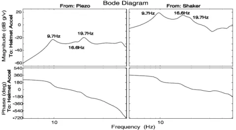
To evaluate the actuation authority of the two active struts, transfer functions from the mechanical shaker and the piezoelectric struts to the mannequin helmet location in the front-back direction were identified experimentally as shown in Figure 7. The transfer functions demonstrated that the vertical vibration input from the mechanical shaker through the Bell-412 pilot seat frame mainly excited the localized mannequin helmet mode at 9.7 Hz and the vertical mannequin body mode at 16.6 Hz. The two stacked piezoelectric struts were configured in parallel as one control channel in the present investigation. This parallel configuration provided effective control authorities to the vibration modes at 9.7 Hz and 19. 7Hz. However, it is important to note that the actual modal parameters could vary depending on the mannequin mass and the seat cushion impedance properties. Therefore, adaptive control laws are required to perform identification of the transfer functions on-line for effective vibration suppression of the aircrew body vibrations when implemented in the helicopter during operation.
Figure 7: Transfer functions from piezoelectric actuator and mechanical shaker
2.2
Adaptive Control Law Development
The helicopter seat and aircrew body vibrations are directly driven by the floor vibration of the vehicle where the seat frame is installed. Within the interested frequency range, it is dominated by N/rev harmonics of rotor dynamic load. As shown in the flight test data, the measured aircrew body vibration was dominated by the 1/rev and 4/rev harmonic peaks while other higher N/rev peaks could be ignored due to the passive damping of the seat cushions. Among the strategies to eliminate harmonic disturbances, the filtered-x feed forward algorithm has been proven effective to cancel the harmonic components while the floor vibration can be used as a reliable reference signal.
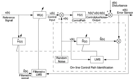
The accelerometer that measured the helmet front-back vibration was selected as the error sensor in the current investigation, while accelerometers in the vertical direction and the aircrew abdomen were monitored for overall performance evaluation purposes. This configuration enabled the implementation of a Single-Input-Single-Output (SISO) control system on the adaptive seat mount as shown in Figure 8. However, reconfigure of the accelerometers and actuators within the proof-of-concept adaptive seat mount hardware could also enable a multiple-input-multiple-output control system for improved performance.
In the block diagram of a SISO adaptive feed forward control law, the control path represents the transfer function between the stacked piezoelectric actuators and the accelerometer at the helmet location. The control path was experimentally identified off-line in this investigation, and approximated as a linear time-invariant (LTI) system, as shown in Figure 7. The floor vibration that drives the seat frame was measured directly using an accelerometer, and used as the reference signal in the adaptive feed forward control law. This approach guaranteed that the control system was purely feed-forward so that the system stability was not affected because no feedback loop was created in the closed-loop system. A robust feedback control law can also be formulated and implemented in parallel with the feed forward control law to suppress the resonant vibration modes that might be present due to random excitations. This paper focused on the evaluation of the adaptive seat mount concept, while details of the control law strategy have been published previously [11].
Figure 8: Adaptive feed-forward algorithm for N/rev harmonics suppression
3.0 EXPERIMENTAL VERIFICATION
Extensive closed-loop control experiments have been conducted on the retrofitted full-scale Bell-412 pilot seat structure. The objective was to verify the reduction of primary N/rev harmonic peaks of the mannequin vibration using representative helicopter floor vibration spectra. The test configuration installed on the mechanical shaker was the same as shown in Figure 5. In the experiments, the “no control” curves represented the cases that the seat was equipped with the passive piezoelectric stack actuators, while the “control” curves represented the cases when the piezoelectric stack actuators were actively controlled by the adaptive feed-forward actuators.
3.1
Sinusoidal Vibration Spectrum Test
Sinusoidal tones were used to simulate the N/rev harmonic excitations of the Bell-412 helicopter. Four major harmonic peaks were generated using the mechanical shaker, namely, 1/rev, 2/rev, 4/rev and 8/rev; and the fundamental frequency was set at 5.4Hz to correlate with the Bell-412 rotor speed. The amplitude of each harmonics was set to 0.03g and the overall input vibration was 0.045grms. Although the input vibration level represented only 25% of floor vibration levels at 120kt cruise flight, the vibration measured on the mannequin helmet was comparable to the level of pilot helmet location during the fight test. This is attributed to the significant impedance differences between the very rigid shaker table and the relatively flexible helicopter
fuselage floor that may have provided additional vibration reduction.
Effective reductions of the mannequin vibration levels at all critical locations have been obtained using the active suspension system. As shown in Figure 9, the four plots described the helmet vibration measured in all three axes as well as the body vibration in the vertical direction. Through adaptive control of the two stacked piezoelectric actuators using the adaptive feed forward control law, the overall vibration levels at the mannequin helmet location and the body location were reduced effectively and simultaneously. The 2/rev harmonics in the front-back direction of the helmet location was reduced by 68%; the 4/rev harmonics reduced by 25% and the overall vibration levels in the front-back direction reduced by 52%. Although the vertical and side vibrations at the helmet location were not included in control strategy design, the overall vibration levels were also suppressed simultaneously, with 10% reduction in the vertical direction and 23% reduction in the side direction. Considering the vibration in all three directions, the equivalent overall vibration level was reduced by 35% at the mannequin helmet location. Moreover, the vibration level at the mannequin abdomen location was also suppressed by 35% with the 2/rev harmonics reduced by 49%. Despite the dynamic nonlinearity of the seat cushion and mannequin body, no significant control spillover was observed during this investigation.
Figure 9: Vibration control results under sinusoidal harmonic profile
3.2
Combined Vibration Profile Test
Closed-loop experiments were also conducted using combined vibration profiles which included the N/rev harmonic tones on top of a background random spectrum. The N/rev harmonic spectrum was kept the same as used previously. The random vibration spectrum covered the frequency range from 4 to 50 Hz as specified by MIL standard, and the level was kept at 0.02grms. This combined vibration input profile provided an overall
vibration level of 0.05grms.
The vibration spectra at the mannequin helmet and body locations were dominated by the 2/rev and 4/rev peaks when not controlled as shown in Figure 10. As expected, the seat with mannequin modes at 9.7 Hz and 16.6 Hz were excited by the random vibration profile. Similarly, the dynamic coupling of the vertical mode at 10.8 Hz with the 2/rev harmonics resulted in the highest peak, and the 4/rev harmonics was also found prominent in the mannequin body vibrations.
The adaptive feed forward control law also achieved simultaneous suppression of the major N/rev harmonics as well as the resonant peaks of the mannequin vibrations. Closed-loop control results demonstrated significant vibration reduction at the mannequin helmet location: the 2/rev harmonics in the front-back direction was suppressed by 69% and the 4/rev harmonics reduced by 50%. For the resonant peaks, the localized helmet bending mode at 9.7 Hz was reduced by 44%. The mode at 16.6 Hz was not controlled effectively. As a result, the overall vibration level in the front-back direction was suppressed by 39%. Similar to the previous control attempt, both the helmet vertical and side vibrations have been reduced, by 7% and 16% respectively. Also, no significant control spillover was observed. The overall equivalent vibration reduction at the helmet location was 26% when considering the vibrations in three directions. Notably, vibration at the mannequin abdomen location was reduced by 33%. The 2/rev and 4/rev harmonics at abdomen location was suppressed by 50% and 26% respectively. The vibration modes at 9.7 Hz and 16.6 Hz at the abdomen location were suppressed by 53% and 23% respectively.
3.2
Results Discussion
It was noted that no appreciable reduction to the 1/rev harmonics was obtained so far. Several factors may have contributed to this effect. Firstly, the objective of feed forward control law is to minimize the root mean square value of the error signal, which was selected as the front-back acceleration at the helmet location in current investigation. This would imply more control weights are applied to the 2/rev and 4/rev harmonics as the amplitudes were significantly higher when compared to 1/rev. Since the 1/rev was lower in frequency, it also required larger stroke from the stacked piezoelectric actuators in order to achieve effective vibration suppression, which was not available with the currently used stack actuators. By assigning the 1/rev harmonics with a higher control weight and using stroke improved stack actuators, reduction of the 1/rev peak could be expected.
In this investigation, the vibration input from the shaker was only 25% of the nominal Bell-412 helicopter floor vibration levels. The control authority of stacked piezoelectric actuators was also intentionally limited to 50% of its full capacity in order to protect the delicate actuator hardware. However, the proof-of-concept adaptive seat mount has shown very promising results in reducing the mannequin body vibration levels without significant modification to the seat structures.
In summary, closed-loop control experiments on the retrofitted full-scale Bell-412 co-pilot seat have demonstrated promising vibration reduction performance. The experiments verified that the active suspension systems on the seat can provide appreciable actuation authority to suppress the major N/rev harmonics as well as the resonant peaks in mannequin vibrations under representative helicopter vibration spectra. By incorporating more advanced controllers and larger stroke actuators, reduction to the 1/rev peak can be expected.
4.0 CONCLUSIONS
This paper investigated an active suspension system implemented on a helicopter seat to mitigate the transmission of vibration to the helicopter aircrew. Flight test results on a Bell-412 helicopter revealed that the aircrew were exposed to high levels of whole body vibration caused by the N/rev harmonics of the rotor aerodynamic load, which may adversely affect their performance and health. Experimental modal test and analysis has been conducted on a Bell-412 pilot seat and identified the major vibration modes that contribute to mannequin body vibration.
An active suspension system was developed and implemented on a full-scale hardware model to reduce the vibration transmitted from the floor to aircrew body. Two stacked piezoelectric actuators have been used as the active struts to provide adaptive vibration attenuation to the seated aircrew. Extensive closed-loop control experiments on a retrofitted full-scale Bell-412 pilot seat have been conducted using a mannequin and representative helicopter vibration input profiles generated by a mechanical shaker. The mannequin whole body vibrations have been suppressed effectively through an adaptive control algorithm of the active suspension system. This investigation verified the effectiveness of the active suspension system to locally reduce helicopter aircrew vibration levels.
REFERENCES
[1] Castelo-Branco, N.A. and Rodriguez, E., “The vibroacoustic disease – an emerging pathology”, Journal of Aviation, Space, and Environmental Medicine, Vol.70, (1), 1999.
[2] Smith D., “Characterizing the effects of airborne vibration on human body vibration response”, Journal of Aviation, Space, and Environmental Medicine, Vol.73, (3), 2002.
[3] Chopra, I., „„Review of State of Art of Smart Structures and Integrated Systems,‟‟ American Institute of Aeronautics and Astronautics Journal, Vol.40, (11), 2002.
[4] Giurgiutiu, V., „„Recent Advances in Smart-material Rotor Control Actuation,‟‟ 41st AIAA Structures, Structural Dynamics and Materials Conference, Atlanta, GA, April 2000.
[5] Staple A. and Wells D., “The development and testing of an active control of structural response system for the EH101 helicopter”, 16th European Rotorcraft Forum, Glasgow, UK, 1990,
[6] “Seats, Helicopter Cabin, Crashworthy, General Specification”, MIL-S-85510(AS), 1981.
[7] Man P.D., Lemerle P. and Verschueren J-P. et al., 2005, “An Investigation of A Semi-Active Suspension for A Fork Lift Truck”, Vehicle System Dynamics, 43(2):107-119.
[8] Cai L. and Chen D., 2004, “A Two-Stage Vibration Isolation System Featuring An Elctroerheological Damper via the Semi-active Static Output Feedback Variable Structure Control Method”, Journal of Vibration and Control, 10(5):683-706.
[9] Hiemenz G. J., Hu W. and Wereley N., 2008, “Semi-Active Magnetorheological Helicopter Crew Seat Suspension for Vibration Isolation”, Journal of Aircraft, 45(3):945-953.
[10] Chen Y., Wickramasinghe V. and Zimcik D.G., 2009, “Development of Adaptive Seat Mounts for Helicopter Aircrew Body Vibration Reduction,” Journal of Vibration and Control, 15(12):1809-1825.
[11] Chen Y., Zimcik D.G. and Wickramasinghe V.K., 2005, “An Adaptive Impedance Control Algorithm for Helicopter Blade Vibration Suppression”, Journal of Vibration and Control, 11(4):543-560.