J O U R N A L O F M A T E R I A L S S C I E N C E 3 4 (1 9 9 9 ) 349 – 353
A versatile plasma technique to improve plastic
materials against gas and water-vapour
permeation
E. M. MOSER∗, C. M ¨ULLER
Swiss Federal Laboratories for Materials Testing and Research EMPA, CH-9014 St Gallen, Switzerland
E-mail: eva.moser@empa.ch
Plasma-enhanced chemical deposition processes have been studied by comparing the performance of flexible diffusion barrier layers on plastic films produced in the same reactor. Under similar experimental conditions, a higher deposition rate is achieved by microwave discharges than by bipolar, pulsed d.c. magnetron sputtering processes. However, with both discharge modes, dense hydrocarbon coatings were produced,
exhibiting a barrier improvement factor up to 120 and a flexibility ranging from 1.1%–8.8% before formation of microcracks started to dominate permeation characteristics. The density of the coatings is 1.0–1.6 g cm−3and their hydrogen content varies from 23%–33%.
C
° 1999 Kluwer Academic Publishers
1. Introduction
Storing food, drugs, delicate materials and microelec-tronic items against environmental influences over a long period of time is a vital problem of our time. New materials or methods for improving existing materials against permeation of gas, water vapour, and substances have to be found to achieve this goal. The conversion of lightweight plastic films into packaging media of high functionality is already being considered as a substi-tute for the metal and glass counterparts. In terms of environmental aspects, the chemically inert and trans-parent polyethylene terephthalate (PET), and similar plastic films, are now widely used. When destroyed by heat, they do not evolve toxic vapours. These prop-erties do not yet fulfil the above mentioned criteria. Laminated structures with several layers of polymeric materials (e.g. EVOH) have been used to compensate for the lower performance in either gas or water per-meation [1]. In addition, plastic films have been coated with thin barrier layers consisting of selected metals or metal oxides. All these coatings should be thin, elastic, free from pinholes and microcracks, and they should not lose their ability to prevent permeation during storage time. Metal oxide barrier layers are optically transpar-ent, microwaveable, and meet the ecological demands but their application range is limited due to their in-trinsic rigidity [2, 3]. Plasma-polymerized coatings of hydrocarbon and monomers containing a source of flu-orine and sulphur atoms have reduced solvent perme-ation in plastic containers [4, 5]. Furthermore, mul-tilayer systems composed of oxide-like barrier layers embedded in polymer-like material have been devel-oped [6]. However, thin hydrocarbon barrier layers
∗Author to whom all correspondence should be addressed. EMPA, CH-9014 St. Gallen, Switzerland.
proved to be a good alternative to the rigid metal oxide barrier layers [7, 8]. In this work, we directly compared the properties of hydrocarbon coatings deposited on to PET films by bipolar, pulsed d.c. magnetron sputter-ing processes and microwave discharges under similar experimental conditions.
2. Experimental procedure
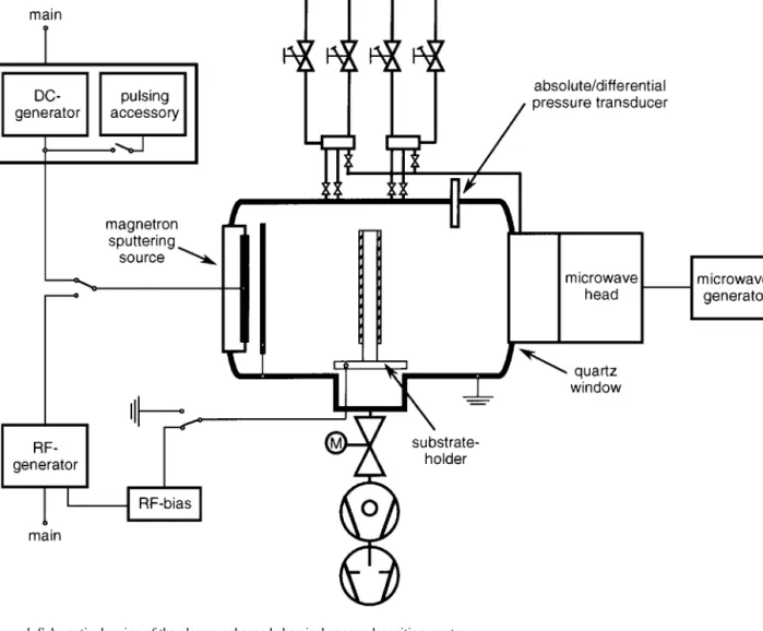
A versatile low-temperature plasma-enhanced chemi-cal vapour deposition reactor was set up, which per-mitted the following treatments to be carried out us-ing variable mixtures of gases, flow rates and workus-ing pressures, i.e. varying known and proven plasma tech-nique parameters: treatment by microwave discharges (MW, 2.448 GHz), radiofrequency (r.f., 13.56 MHz), and direct current (d.c.) sputtering by circular mag-netrons, while biasing the sample by r.f., d.c., or earth-ing (Fig. 1). The complete installation was controlled by an universal electronic system in which all energy gen-erators worked in variable controllable modes and were equipped with a power supply for generating pulsed and non-pulsed operating modes.
The starting pressure in the reactor was∼10−6mbar. After optimization, the experimental parameters were set to a MW/d.c. input power of 100 or 200 W, respec-tively. In the case of d.c. magnetron sputtering pro-cesses, a pulse frequency of 25 kHz, a reverse volt-age of 15% of the operating d.c. input voltvolt-age, and a
reverse recovery time of 2 µs were chosen, whereas
microwave discharges were performed in continuous mode by monitoring MW input power and frequency. The target consisted of a circular hot-pressed carbon
Figure 1 Schematic drawing of the plasma-enhanced chemical vapour deposition reactor.
disc (purity 99.999%), 6.3 mm thick, bonded to a cop-per plate.
For non-reactive d.c. sputtering processes (coatings A), the deposition time was 10 min, 2 min for reactive gas mixtures (coatings B and C) and 1 min for MW-activated processes (coatings D). The working pressure was regulated by a butterfly valve connected to a bara-tron gauge.
The samples were either connected to earth or were biased by a capacitively coupled radio frequency (Vb= −40 or −90 V). The substrate temperature was
mea-sured by a thermocouple attached to the sample holder surface. The temperature ranged from room tempera-ture (23◦C) to a maximum value of 29◦C for extreme conditions (200 W MW power). Polythylene
tereph-thalate (PET) film, DuPont-MYLAR® type A, with a
thickness of 12µm and a piece of silicon wafer [1 0 0] placed adjacent to the PET-film were used as substrates. Oxygen permeability was measured at 0% relative
humidity, 23◦C, according to ASTM D 3985-81,
us-ing a Mocon OX-TRAN 2/20 instrument. Water-vapour transmission measurements were conducted with a Lyssy Vapour Permeation Tester L 80-4000. Total lu-minous transmittance of the coated and untreated PET films was investigated according to ASTM D 10003-92 (CIE: Y-value, 10◦, D65).
Coating thickness was determined by profilometry (Tencor P10) on pieces of silicon wafer. The hydrogen content, possible impurities, and the density of coat-ings were analysed on coated Si[1 0 0] substrates using Rutherford backscattering (RBS), elastic recoil detec-tion analysis (ERDA), and X-ray photoelectron spec-troscopy (XPS). Internal tension of the coated PET-films was investigated by evaluation of curvature.
Stretching of the coated films allowed the analysis of their elastic behaviour by a method based on in-terferometry. The technique developed at EMPA will be described in more detail elsewhere [9]. Microcrack formation on the elongated sample and its influence on diffusion barrier properties was established by the combination of scanning electron microscopy and per-meability measurements. After having etched the PET samples with 80% sulphuric acid, coating defects were investigated. The AFM images of the substrate and the coated PET films were captured under ambient condi-tions using a Bioscope-AFM (Digital Instruments) and an Explorer-AFM (TopoMetrix, Model TMX 2000) in tapping mode and non-contact mode of operation, re-spectively.
All tests were compared with a dummy film from the same batch of material. A periodic inspection study of the diffusion property of a carefully stored sample
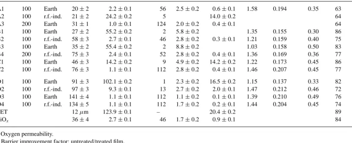
T A B L E I Summary of properties of amorphous hydrocarbon films
Thicknessa OXTRa Elongation Waterc ρ
Md ρNe
Sample Power Bias (nm) (cm3(m2d bar)−1) BIFb (%) (g m−2d−1) (g m−3) (g at cm−3) H-cont.f Transm.g
A1 100 Earth 20± 2 2.2± 0.1 56 2.5± 0.2 0.6± 0.1 1.58 0.194 0.35 63 A2 100 r.f.-ind. 21± 2 24.2± 0.2 5 14.0± 0.2 64 A3 200 Earth 31± 1 1.0± 0.1 124 2.0± 0.2 0.4± 0.1 64 B1 100 Earth 27± 2 55.2± 0.2 2 5.8± 0.2 1.35 0.155 0.30 86 B2 100 r.f.-ind. 58± 3 2.7± 0.1 46 2.8± 0.2 0.3± 0.1 1.21 0.159 0.40 75 B3 100 Earth 35± 2 55.4± 0.2 2 8.8± 0.2 1.03 0.158 0.50 83 B4 200 r.f.-ind. 75± 3 2.4± 0.1 52 2.8± 0.2 0.4± 0.1 1.36 0.169 0.36 77 C1 100 Earth 46± 3 14.2± 0.2 9 4.9± 0.2 14.2± 0.2 1.22 0.173 0.45 86 C2 100 r.f.-ind. 76± 3 1.1± 0.1 112 2.8± 0.2 0.4± 0.1 1.46 0.207 0.45 77 D1 100 Earth 91± 3 102.1± 0.2 1 2.3± 0.2 16.5± 0.2 1.15 0.137 0.33 82 D2 100 r.f.-ind. 97± 3 9.3± 0.1 13 2.7± 0.2 2.0± 0.1 1.47 0.212 0.46 72 D3 100 Earth 141± 4 1.1± 0.1 112 1.1± 0.2 0.1± 0.1 1.39 0.210 0.49 76 D4 100 r.f.-ind. 134± 5 1.1± 0.1 112 1.7± 0.2 0.2± 0.1 1.44 0.204 0.45 74 PET 12µm 123.9± 0.1 – 20.4± 0.2 89 SiOx 36± 4 2.7± 0.1 46 1.7± 0.2 0.9± 0.1 84 aOxygen permeability.
bBarrier improvement factor: untreated/treated film. cWater vapour permeability.
dMass density.
eGram atom number density. fAtomic fraction of hydrogen [C
1Hx].
gTotal luminous transmittance (Y-value: CIE).
(23◦C, 0% relative humidity) was undertaken in order to analyse long-term behaviour.
3. Results
3.1. Magnetron sputtering deposition
Fig. 2a and b show plots of coating thickness of sam-ples prepared at the same deposition time and oxygen permeation versus d.c. input power, respectively. Coat-ing thickness increases with power for both pulsed and non-pulsed modes of operation. With increasing power, oxygen permeation increases for the non-pulsed coat-ings, whereas for pulsed coatings best barrier properties with an improvement factor of about 120 are achieved at 200 W d.c. input power.
The optimal pressure for this process is between 2
and 5× 10⁻³ mbar. In this range almost no internal
tensions of the coatings arise. The coatings are homo-geneous over a diameter of about 120 mm even under the variation of the working distance between 80 and 160 mm. The coatings were observed to be slightly brownish but the general transparency is acceptable for specific industrial applications.
Table I presents the properties of the coatings (A–C) produced by bipolarly pulsed d.c. magnetron processes. The barrier improvement factor for oxygen (BIF) is in-dependent of the substrate thickness and its permeabil-ity and is a function of the coating defect parameters. A correlation with the water vapour data is observed. So far, an elongation value of more than 5% has been achieved for coatings with lower permeation perfor-mance.
Although the deposition rate of the processes de-scribed could not be increased by pulsing d.c. mag-netron discharges, a significant improvement of the bar-rier layer results, as already described elsewhere [7]. The same performance properties as summarized in Table I were obtained for coated samples stored for 6 months at defined conditions.
3.2. Microwave discharge deposition
In the same reactor under similar experimental condi-tions as used for d.c. magnetron sputtering processes, hydrocarbon films were deposited on PET films by
Figure 2 Characteristics of hydrocarbon layers (performed by d.c. mag-netron sputtering in an argon plasma) as a function of d.c. input power in (d, r) pulsed mode and in (s, e) non-pulsed mode. (a) Coating thickness (nm), (b) oxygen permeability (cm3(m2· d · bar)−1).
microwave discharges. For MW processes, the depo-sition rate is increased by a factor of eight (coating D3 compared to coating B3), taking into account the dif-ferent deposition time. If the gas flow is increased, the functional performance and the deposition rate of the MW coatings (D1–D4) are improved, in contrast to the d.c. coatings (B1–B4).
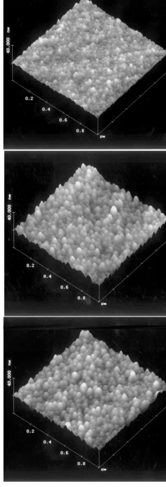
In Fig. 3a, the AFM image of an untreated PET-film reveals a morphology consisting of 10–20 nm sized grains and an RMS roughness of about 0.8 nm. All investigated coatings show a very homogeneous mor-phology with an RMS roughness of 1.5–2.5 nm and a grain size of 20–40 nm. The structure of the films is very similar and depends neither on the discharge mode, nor on the deposition parameters. The grain size of the MW-coated PET film (D4, Fig. 3c) is slightly enhanced compared to the d.c. coating (C2, Fig. 3b), which is most probably due to the higher coating thick-ness. In the 20µm micrometre scale, an unidirectional orientation of the biaxially stretched PET substrate with an RMS roughness of 11–22 nm is observed. The ori-ented mounds on the substrate surface have also been found in the coated PET films and have been confirmed using SEM.
3.3. Influence of r.f. biasing
The samples were either earth biased or the radiofre-quency was capacitively coupled to the substrate holder. Because of the negative potential on the substrate, ions are accelerated in the sheath towards the substrate, im-pinging on it with a higher energy. The density of the coatings (C2, D2, and D4) is expected to be higher and the permeability values to be lower. However, the flexi-bility of the coatings decreases with increasing density for d.c. discharge mode. In addition, the deposition rate is increased by applying r.f. biasing. As far as MW coat-ings are concerned, r.f. bias has a positive effect on the properties of the samples (D2, D4).
The permeability of the r.f.-biased sample A2 is significantly increased compared to sample A1. Here, the equilibrium of ion bombardment controlled by the plasma potential and the negative bias voltage at the film surface seems to be negatively influenced by etch-ing processes of the substrate surface. As a result, more pinholes were observed in sample A2 than in A1.
4. Discussion
Under similar experimental conditions, microwave dis-charge processes lead to a faster film growth which is most probably due to the relatively highly dissociated plasma conditions [10]. Additional work is required to elucidate the process parameters for optimal mechani-cal and chemimechani-cal properties in order to fulfil the required functional performances. Because the coatings showing good diffusion barrier properties are characterized by a gram atom number density higher than 0.2 g at cm−3, we prefer to describe the developed coatings as dense hydrocarbon films, according to Angus [11].
The reduction in permeation is limited by the trans-port through coating defects, such as pinholes, grain boundaries or microcracks [3]. So far, AFM and TEM [7] investigations of the presented samples have
Figure 3 AFM images show topography of PET substrate and hydro-carbon layers. (a) Uncoated PET (reference; 1000× 1000 nm, 0–40 nm vertical scale, grain size 10–20 nm, RMS roughness 0.8 nm). (b) 76 nm thick C:H layer on PET (C2, 100 W d.c.; biased; 1000× 1000 nm, 0–40 nm vertical scale, grain size 25–35 nm, RMS roughness 2.0 nm). (c) 134 nm thick C:H layer on PET (D4, 100 W MW; biased; 1000× 1000 nm, 0–40 nm vertical scale, grain size 30–40 nm, RMS roughness 1.5 nm).
revealed a very homogenous morphology for the coat-ings with an RMS roughness of about 2 nm and a grain size of about 30 nm on a unidirectional structured PET film. The anisotropy of the biaxially stretched substrate with an RMS roughness of about 16 nm is most proba-bly due to the manufacturing process. Extrusion-related surface defects have already been observed by Finch et al. [8]. These inhomogenities show up in the coated PET films because the very thin coatings are not able to smooth the microscale structure. As far as coating defects are concerned, some pinholes were observed on the coated PET films, most probably due to coated dust particles which were removed later [7]. Further-more, we are convinced that the good adhesion of the hydrocarbon coatings on the substrate plays a crucial role in microcrack formation and permeation behaviour because the effective area of each microcrack is en-hanced due to lateral diffusion of the gas in the polymer near the interface with the barrier coating.
Permeabil-ity measurements on SiOx-coated PET films indicate
that peeled-off regions and pinholes in the barrier layer are responsible for their higher permeation data com-pared to the SiOx-bulk value extrapolated to the same
thickness [12].
5. Conclusions
These studies highlight some of the possibilities for improving polymer materials, with respect to gas and water vapour permeation, presented by plasma tech-nology. Detailed evaluation of other possible plasma procedures, such as radiofrequency plasma processes with our reactor will enable us to find out the simplest, most effective and least costly way to arrive at our goal. New results will be presented in future reports.
Acknowledgements
The work was supported by the Swiss Foundation for Technology and Innovation under no. 2377.1. The authors are grateful to R. Urech for technical assis-tance, Dr Z. Harmati for measuring oxygen ity, E. Furrer for carrying out water-vapour permeabil-ity measurements, Dr E. Hack for developing a tech-nique to analyse the formation of microcracks, Dr D. Anselmetti, Novartis Services AG, and Dr H. K¨unzli for recording AFM images, and Dr S. Mikhailov and Dr J. Weber, Universit´e de Neuchˆatel, for performing RBS and ERD analysis.
References
1. J. R E L L M A N NandH. S C H E N C K, Kunststoffe 82 (1992) 2. 2. J. E. K L E M B E R G-S A P I E H A, L. M A R T I N U, O. M.
KU T T E L¨ and M. R. W E R T H E I M E R, in “Proceedings of the 36th Annual Technical Conference on SVC,” Dallas (1993) pp. 445–9.
3. H. C H A T H A M, Surf. Coat. Technol. 78 (1996) 1.
4. Y. L I NandH. Y A S U D A, J. Appl. Polym. Sci. 60 (1996) 2227, and references therein.
5. J. F. F R I E D R I C H,L.W I G A N T,W. U N G E R,A.L I P P I T Z, H. W I T T R I C H, D. P R E S C H E R, J. E R D M A N N, H.-V. G O R S L E RandL. N I C K, J. Adhes. Sci. Technol. 9 (1995) 1165. 6. M. W A L T H E R,M. H E M I N G, andM. S P A L L E K, Surf. Coat.
Technol. 80 (1996) 200.
7. E. M. M O S E R,R. U R E C H,E. H A C K,H. KU N Z L I¨ and E.MU L L E R¨ , in “Proceedings of the 10th International Conference on Thin Films,” Salamanca, September 1996, in press.
8. D. S. F I N C H, J. F R A N K S, N. X. R A N D A L L, A. B A R N E T S O N,J. C R O U C H,A. C. E V A N SandB. R A L P H, Packag. Technol. Sci. 9 (1996) 73.
9. E. H A C KandE. M. M O S E R, J. Mater. Sci. Lett., submitted. 10. K. L A N G E, Diss. Techn. Universit¨at M¨unchen (1995). 11. J. C. A N G U S, Thin Solid Films 142 (1986) 145. 12. K. K E S S L E R, Diss. ETH Nr. 10794, Z¨urich (1994).
Received 16 June 1997 and accepted 23 July 1998