BIOSAND HOUSEHOLD WATER FILTER PROJECT IN NEPAL
By
Tse-Luen Lee
B. A. Sc. Civil Engineering
University of Toronto, 2000
SUBMITTED TO THE DEPARTMENT OF CIVIL AND ENVIRONMENTAL ENGINEERING IN PARTIAL FULFILLMENT OF THE REQUIREMENTS FOR THE
DEGREE OF
MASTER OF ENGINEERING IN CIVIL AND ENVIRONMENTAL ENGINEERING AT THE
MASSACHUSETTS INSTITUTE OF TECHNOLOGY
JUNE 2001 MASSACHUSETTS INSTITUTE
OF TECHNOLOGY ( 2001 Tse-Luen Lee. All Rights Reserved
The author hereby grants to MIT permission to reproduce
and to distribute publicly paper and electronic
LIBRARIES
copies of this thesis document in whole or in part.
BARKER
Signature of Author:
D rtment of Civil and Environmental Engineering
May 11, 2001
Certified by: A
Susan E. Murcott Lecturer of Civil and Environmental Engineering Thesis Supervisor
Accepted by:
Oral Buyukozturk t Chairman, Committee for Graduate Students
BIOSAND HOUSEHOLD
WATER FILTER PROJECT IN
NEPAL
by
Tse-Luen Lee
Submitted to the Department of Civil and Environmental Engineering on May 11, 2001 in
partial fulfillment of the requirements for the degree of Master of Engineering in Civil and
Environmental Engineering
Abstract
This purpose of this study was to investigate the effectiveness and the performance of the
BioSand filter in Nepal. To achieve this, the author undertook a field trip to Nepal in
January, 2001. The trip was made possible with generous support provided by the
Department of Civil and Environmental Engineering of MIT. The author spent 3 weeks in
Nepal
-
4 days in the vicinity of Tansen in the central Palpa region and 9 days in the
Nawalparasi district in the Terai collecting water samples. Turbidity measurements were
taken and presence/absence tests for total coliform, E.coli and H2S producing bacteriawere carried out. At MIT, membrane filtration tests were also carried out. This study
found that while filtered water from the BSFs in Nepal has low turbidity and flows at a
sufficiently high rate, only 9 out of 12 properly functioning BSFs removed total coliform
and 10 out of 12 properly functioning BSFs removed E. coli. Membrane filtration tests
carried out in MIT indicate that the BSF technology is effective at removal of total
coliform with an average removal of 99.5% of total coliform in the source water. Based
on the effectiveness of the BSF in removing microbial contamination, the author
recommends the BSF technology to be adopted on a large scale in Nepal, but only if it is
coupled with a monitoring plan to ensure correct construction, operation and maintenance
procedures are followed. A monitoring plan is necessary to reduce the fraction of
BioSand filters that were not working properly.
Supervised by: Susan E. Murcott
ACKNOWLEDGMENTS
Thanks to all the people who have helped me through my graduate career, including the following:
Thesis supervisor, Susan Murcott, who offered invaluable advice and guidance all the way from the start of the project till the day this thesis was handed in, and who took time to meticulously read through numerous drafts;
Faculty advisor, Dr. Eric Adams, who gave me the flexibility to choose the subjects that stimulate my learning in this institute;
The Nepal group a.k.a. Naiad Engineering for making my stay in Nepal unforgettable: Nat, Meghan, Tim, and Jessie;
Friends who kept me sane and made living in Cambridge enjoyable: Kirill, Fiona, Shan, Thor, Thomas Moore, Takashi, Shao-Hwei, Anthony, Wesley, Woody, Romeo, Win, William,
Nadine, Tee and many more;
Friends we met in Nepal: Kaanchu, Tili and others at the luxurious Hotel White Lake in Tansen;
Friends back home in Singapore whom I have temporarily ignored while working on this thesis, for their kind understanding;
Xin-Yun, for her support during the stressful times;
This thesis is dedicated to the many kind people Nat and I met in Nepal, including the young boy who sat in our jeep as we went around Tansen in search for the next BioSand fiter. I sincerely hope that this thesis will, in some way, contribute to the
BioSand Household Water Filter Project in Nepal Table of Contents
TABLE OF CONTENTS
1
IN TRO DU CTIO N ...
11
1.1 Purpose of Study... 12
1.2 A Brief H istory of Slow Sand Filters...13
1.3 H istory of The BioSand Filter ... 17
2
TH EO RY ...
22
2.1 Contrast Between Slow Sand Filter and Rapid Sand Filter...22
2.2 Contrast Between BioSand Filter and Slow Sand Filter ... 24
2.3 The Schm utzdecke ... 25
2.4 Biological Removal M echanisms ... 25
2.4.1 M etabolic breakdown ... 26
2.4.2 Bacterivory... 26
2.5 Physical Removal M echanism s ... 27
2.5.1 Surface straining... 27
2.5.2 Inter-particle Attraction ... 28
2.6 Filter Ripening ... 29
2.7 Previous BioSand Filter Results ... 29
3
ELEMENTS OF A BIOSAND FILTER ...
31
3.1 Concrete Body/Shell ... 32
3.1.1 Riser pipe assembly ... 34
3.1.2 Preparation of m old ... 34 3.1.3 M ixing concrete... 36 3.1.4 Concrete Pour... 38
3.1.5
De-molding ...
39
3.2 D iffuser Plate... 41 3.2.1 M aterials ... 41 3.2.2 Design ... 433.3 Sand and Gravel... 46
BioSand Household Water Filter Project in Nepal Table of Contents
3.3.2 Preparation ... 47
3.4 Lid ... 49
4
EVALUATION METHODOLOGY OF BIOSAND FILTER ...
50
4.1 M icrobial Tests ...
50
4.2 Turbidity... 554.3 Flow Rate ...
56
4.4 Physical Observations ...
58
4.4.1
Spouts Attachment...
58
4.4.2
D iffuser Plate...
59
4.4.3
Sand Layer ...
59
4.4.4
Cracks in the Concrete Body...
59
5
RESULTS AND DISCUSSIO N ...
60
5.1 M icrobial Tests Results...
60
5.2 Turbidity Results...
62
5.3 Flow Rate Results ...
64
5.4 Physical Observation Results ...
65
5.4.1
Spouts Attachment...
65
5.4.2
Diffuser Plate...
67
5.4.3
Sand Layer ...
68
5.4.4
Cracks in Concrete Body ...
70
5.5 Correlations ...
71
5.6 Drawbacks ...
71
6
EXPERIMENTS CARRIED OUT AT MIT ...
73
6.1 M em brane Filtration ...
73
6 .2 p H ... 7 5
7
SUM M A RY AND CO NCLUSIO NS ...
76
REFEREN CES ...
78
APPENDIX A: LIST OF EQUIPMENT USED DURING FIELD TRIP IN NEPAL 82
APPENDIX B: TURBIDITY MEASUREMENT STATISTICS ...
83
APPENDIX C: FIELD TEST RESULTS...89
LIST OF FIGURES
Number Page
FIGURE
1:
ARJUNG.C.
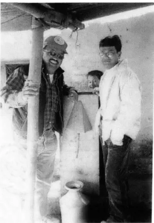
OF HOPE FOR THE NATION (LEFT), BIOSAND FILTER (MIDDLE) AND ATECHNICIAN (RIGHT) IN NEPAL.
12
FIGURE 2: A SCHEMATIC OF THE
UNICEF
FILTER, AN UPFLOW HOUSEHOLD SLOW SANDFILTER (FROM [GUPTA AND CHAUDHURI, 1992]) 21
FIGURE 3: CROSS-SECTION OF A CONCRETE BIOSAND FILTER 31
FIGURE 4: PLASTIC BSF FROM DAVNOR WATER TREATMENT TECHNOLOGIES LTD. 33
FIGURE 5: CONCRETE BSF MADE FROM SHOP DRAWINGS PROVIDED BY DAVNOR WATER
TREATMENT TECHNOLOGIES LTD. 33
FIGURE 6: CONCRETE BSF WITH SQUARE BASE. 33
FIGURE 7: CONCRETE BSF WITH ROUND BASE. 33
FIGURE 8: PVC PIPE DIMENSIONS (NOT TO SCALE) 34
FIGURE 9: UNASSEMBLED STEEL MOLD - INNER MOLD (LEFT) AND OUTER MOLD (RIGHT). 36
FIGURE
10:
STEEL MOLD FOR CONCRETE BSF SHELL (ASSEMBLED) 36FIGURE 11: CONCRETE MIXING
I
37FIGURE 12: CONCRETE MIXING
II
38FIGURE 13: TAMPING THE CONCRETE MIXTURE WITH A WOODEN ROD 39
FIGURE 14: A TYPICAL METAL DIFFUSER PLATE WITH HANDLE IN NEPAL 42
FIGURE 15: LOW DENSITY POLYETHYLENE PLASTIC (LDPE) DIFFUSER PLATE IN NEPAL 43
FIGURE
16:
METAL DIFFUSER BASINI
44FIGURE 17: METAL DIFFUSER BASIN II 45
FIGURE
18:
A METAL POT USED AS A DIFFUSER BASIN IN A ROUND BSF 45FIGURE 19: A SCREW TO AID LIFTING THE DIFFUSER PLATE OUT OF THE BSF 46
FIGURE 20: SIEVES FOR SAND AND GRAVEL 49
FIGURE 21: P/A BROTH IN GLASS AMPULE. 52
FIGURE 22: PATHOSCREENTM MEDIUM PILLOWS.
52
FIGURE 23: WATERCHECKTM TEST KIT
53
FIGURE 24: HACH POCKET TURBIDIMETER 56
FIGURE 25: MEASURING FLOW RATE 57
FIGURE 26: BSF MICROBIAL RESULTS
61
List of Figures
FIGURE 27: DISTRIBUTION OF OBSERVED PROBLEMS WITH THE BSF
61
FIGURE 28: TURBIDITY REMOVAL RESULTS.
63
FIGURE 29: DISTRIBUTION OF PERCENTAGE TURBIDITY REMOVAL FOR FILTERS THAT WERE
WORKING PROPERLY.
64
FIGURE
30:
DISTRIBUTION OF FLOW RATE65
FIGURE 31: INTERMEDIATE STORAGE CONTAINER FOR FILTERED WATER
66
FIGURE 32: SPOUT IS NOT PLUGGED, ALLOWING CONTINUOUS FLOW.66
FIGURE 33: A FLOATING LDPE DIFFUSER PLATE.
67
FIGURE 34: DISTURBED TOP LAYER OF FINE SAND.
68
FIGURE 35: WATER LEVEL AT REST BELOW TOP LAYER OF FINE SAND. 69 FIGURE 36: WATER LEVEL AT REST MORE THAN 5CM ABOVE THE TOPMOST SAND LEVEL.
69
FIGURE 37: A CRACKED BSF THAT WAS MENDED BY A TECHNICIAN 70 FIGURE 38: MF RESULTS - CHARLES RIVER WATER BEFORE FILTRATION (LEFT); AFTERFILTRATION (RIGHT) 75
LIST OF TABLES
Number Page
TABLE 1: TYPICAL TREATMENT PERFORMANCE OF CONVENTIONAL SLOW SAND FILTERS
(COLLINS, 1998) 17
TABLE 2: TYPICAL DIFFERENCES BETWEEN SLOW SAND FILTER AND RAPID SAND FILTER 23
TABLE 3: DIFFERENCES BETWEEN BSF AND SLOW SAND FILTER 25
TABLE 4: CONTAMINANT REMOVAL EFFICIENCY OF BIOSAND FILTER 30
TABLE 5: BSF DESIGN PARAMETERS 32
TABLE 6: NUMBER OF SAMPLES ANALYZED 60
TABLE 7: SUMMARY OF CORRELATIONS 71
TABLE 8: MEMBRANE FILTRATION RESULTS 74
TABLE 9: PH VALUES OF WATER BEFORE AND AFTER FILTRATION 75
1
INTRODUCTION
The BioSand Filter (BSF) is a household-scale slow sand filter developed by Dr. David Manz of the University of Calgary, Canada. This filter has been tested by several government, research and health institutions as well as NGO agencies in Canada, Vietnam, Brazil, Nicaragua, and Bangladesh. A Nepali NGO, Hope For The Nation, has been promoting the filter in the central foothill region of Palpa and the southern flatland region of Nawalparasi.
The filter was formerly called the Canadian Water Filter (CWF). The new legal and registered name of is "The BioSand Filter Using the Award-Winning CWF Design" or its short form, "BioSand Filter" (Ritenour, 1998). The filter was also given other names describing its intermittent process such as "Intermittent Operated Slow Sand Filter" (IOSSF) and "Manz Intermittent Slow Sand Filter" (MISSF) (Palmeteer et al., 1997). The filter was also called the "BioSand Water Filter" (BWF) in Cambodia and "Guras Water Filter" in Nepal after the national flower (Chettri, 2001b). Other names based on its physical appearance include "Barrel Filter" and "Cement Filter" (IDRC Module 5, 1998). In this thesis, the term "BioSand Filter" or BSF will be used.
Figure 1: Arjun G.C. of Hope For the Nation (left), BioSand Filter (middle) and a technician (right) in Nepal.
1.1
PURPOSE OF STUDY
This purpose of this study was to investigate the effectiveness and the performance of the BioSand Filter in Nepal. To achieve this, the author undertook a field trip to Nepal in January, 2001. The trip was made possible with generous support provided by the Department of Civil and Environmental Engineering of MIT.
The author spent 3 weeks in Nepal, 4 days in the vicinity of Tansen in the central Palpa region and 9 days in the Nawalparasi district in the Terai investigating the BSF pilot project in Nepal. The remainder of the time was spent in Kathmandu. The Palpa region is in the foothills of the Himalayas and is a highly mountainous terrain. The pilot project was started in these 2 locations in Nepal about 2 years ago by a local NGO; Hope for the Nations (HFTN), Nepal.
BioSand Household Water Filter Project in Nepal Introduction
Currently, there are a total of 15 such filters in Tansen (Chettri, 2001a) and more than 100 in
Nawalparasi (Magar, 2001) and the numbers are increasing.
1.2
A BRIEF HISTORY OF SLOW SAND FILTERS
Slow sand filters have filtration rates of 0.1m/h as opposed to rapid sand filters that have
filtration rates of 10m/h (Haarhoff and Cleasby, 1991). Slow sand filters have been used to
deliver potable water to the public since the early nineteenth century. The first recognized use
of slow sand filtration for water supply was in Paisley, Scotland in 1804 when John Gibbs set
up an experimental slow sand filter to supply his bleachery and sold excess treated water to the
townspeople (Baker, 1981). By 1852 the health advantages of filtered water were so evident
that the Metropolis Water Act required all Thames River water to be filtered before use by
Londoners. The 1854 Broad Street cholera outbreak further reinforced the need to filter public
supply. Since then slow sand filters have been adopted by many major European cities
including London, Amsterdam and Zurich for potable water treatment and are still in use
today as a secondary filtration step (Baker, 1981).
The development of slow sand filtration in the United States, in contrast with the European
experience, was slow (Logsdon and Fox, 1988). The year 1832 saw the first slow sand filtration
plant in the United States built in Richmond, Va. In 1833, the plant had 295 water subscribers.
The next US plant to open was in Elizabeth, N.J., in 1855. Slow sand filters were introduced in
Massachusetts in the mid-1870s. Sand filters and other treatments were primarily designed to
improve the aesthetic quality of water. It took major developments in bacteriology during the
1870s and 1880s to demonstrate that microorganisms that exist in water supplies can cause
human and animal diseases. This led to the realization that water treatment could help prevent
theory of disease, and the Scottish surgeon Joseph Lister were major players in this work. By the 1890s filtration was gaining recognition for not only straining out undesirable particles, but also removing deadly germs. Towns and cities along the Hudson River in New York State that used filtration for water purification had fewer outbreaks and incidences of typhoid than communities that did not filter the Hudson River water.
Installation of both slow rate and rapid rate filtration plants took place in the 1890's and 1900's, but shortly thereafter, rapid filters gained popularity. By 1940, the United States had about 100 slow sand filtration plants, whereas nearly 2300 rapid rate plants had been constructed (Baker, 1981). A number of factors may have been involved in this shift in interest. River water that was muddied by runoff from clay soils could be treated successfully with properly designed and operated rapid rate filtration plants. Such waters, on the other hand, clogged slow sand filters. Additional advantages for medium-sized and large water utilities were the reduced land requirements in populated areas and the lower labor requirements in operations and maintenance for rapid filters compared to slow filters (Logsdon, 1991).
In the late 1970's and early 1980's, the potential for application of slow sand filtration in the United States was reconsidered. Increase in outbreaks of waterborne giardiasis in the USA throughout the 1970's played an important role in the renewed interest in slow filters. Most giardiasis outbreaks had occurred in places where the raw water was of low turbidity and therefore appeared suitable for treatment by slow sand filtration. Although there was plenty of evidence that slow sand filters remove bacterial and viral contaminants, there was no data to verify that slow filters remove Giardia cysts. As a result, the U.S. EPA sponsored several
research projects in the early 1980's to determine the capabilities of slow sand filtration, which includes controlling Giardia cysts in surface waters (Graham, 1988).
The success of these projects led to a program of research in slow sand filtration at institutions such as Iowa State University, Ames; Colorado State University, Fort Collins; Syracuse University, Syracuse; Utah State University, Logan; University of Washington, Seattle; and University of New Hampshire, Durham (Weber-Shirk and Dick, 1997). There was also evaluation of slow filters in the state of New York, and the province of British Columbia in Canada. Limitations for use by large water utilities were recognized, but the process was considered for use by small systems, where requirements for land and labor would not be a serious drawback.
In 1980, the United Nations declared the beginning of the International Drinking Water Supply and Sanitation Decade. Provided that water demands were not too high and that sufficient land was available, the only water treatment considered reliable and recommended
for developing nations was slow sand filtration (Graham, 1988).
In 1985, the Surface Water Treatment Rule (SWTR) was passed in the United States; this regulation requires filtration and disinfection as minimum treatment for surface water. Although only about 50 slow sand filtration plants were in operation in the United States in 1991 (Schuler et al., 1991), more plants may be built as small communities (as well as places like campgrounds, adult and youth camps, and rural conference centers) comply with the SWTR. Slow sand filters in the United States are found primarily in smaller communities with fewer than 10,000 people, 45% of which serve fewer than 1,000 people (Sims and Slezak,
1991).
Introduction
Slow sand filtration has also been found to be a highly efficient means of removing the protozoan parasite, Cryptosporidium parvum, from water (Timms et al., 1994). In recent years, this parasite has been recognized as a significant threat to potable supplies. The resistant stage
- an oocyst - is relatively untouched by chlorine disinfection. In experiments performed by Thames Water Utilities, United Kingdom, slow sand filters reduced concentrations of Cryptosporidium oocysts by 99.997% from 4000/L to 0/8L (Timms et al., 1994). Another study in British Columbia by Fogel contradicts the aforementioned study (Fogel et al., 1993). Fogel found removal efficiencies of 48%; this figure is significantly different from the 100% removals from previous literature. However, a point to note concerning the British Columbia filters is that they were operating well out of the range of the recommended design limits for the uniformity coefficient' at 3.5 (Fogel et al., 1993). Furthermore, temperature can adversely affect the performance of a slow sand filter; the British Columbia filters were operating at extremely low temperatures of less than 1C (Fogel et al., 1993). Overall, the literature supports data that strongly suggests slow sand filtration is a viable option for Crjptosporid&a removals.
Although slow sand filtration often has been replaced by faster and more advanced high-rate filtration methods, its low cost, ease of operation, minimal maintenance requirements, and success in removing pathogenic microorganisms make slow sand filtration an attractive option for rural communities and developing nations (Collins et al., 1992). The following table shows the typical treatment performance of conventional slow sand filters.
Introduction
Table 1: Typical treatment performance of conventional slow sand filters (Collins, 1998)
Parameters Values
Turbidity <1.0 NTU
Coliforms 1-3 log units
Enteric Viruses 2-4 log units
Giardia Cysts 2-4+ log units
Cryptosporidium Oocysts >4 log units
Dissolved Organic Carbon <15-25% Biodegradable Dissolved Organic Carbon <50%
Trihalomethane Precursors <20-30%
Zn, Cu, Cd, Pb >95-99%
Fe, Mn >67%
As <47%
1.3
HISTORY OF THE BIOSAND FILTER
In 1987, when Dr. Manz flew to the Zulu homeland in South Africa as part of an international development project, he found himself in a world of perpetual illness, high infant mortality and rampant fatalism (Pearce-McLeay, 1996). International aid organizations had come and gone, leaving in their wake scattered springs, bored holes and instructions to boil or chlorinate the community water supply (University Technologies International, 1998). Driven by the desire to help the developing world find a better way, Manz spent the next few years developing a simple, cheap and effective filtration system (Legge, 1996). The filter design was
based on a new form of slow sand filtration, replacing the continuous process used since the
late 19 century.
The first prototype was out in 1988. In initial tests run by the Public Health Laboratories at Calgary's Foothill Hospital in the fall of 1988, the filter eliminated 99 per cent of fecal coliform
(University of Calgary, 1994).
In the fall of 1991, research into what was initially called "the Canadian Water Filter" was initiated in the Department of Civil Engineering of the University of Calgary. Initial positive results convinced the Pan American Health Organization (PAHO), through the Centro Latinoamericano de Perinatologia y Dessarollo Humano (Latin American Center for Peninatology and Human Development) or CLAP, to invest USD$10,000 from one of its projects known as Proyecto de Desarollo de la Salud Perinatal (Development of Perinatal Health Project) or DESAPER into a pilot Canadian Water Filter evaluation project in Nicaragua. DESAPER is a program to develop maternal, perinatal and child health in selected areas of Bolivia, Honduras, Nicaragua, and Peru (University of Calgary, 1994). It is funded by the Canadian International Development Agency (CIDA) and is co-administered by the Division of International Development of the University of Calgary and CLAP. Subsequent to the successful initiation of the pilot project, an additional USD$8,000 was provided to expedite and continue research into technology (University of Calgary, 1994). Based on the success of the pilot project, Health Canada provided an additional USD$60,000 to the University of Calgary for a Phase Two of the water filter project in Nicaragua and a second pilot project in Honduras. This was because Health Canada saw significant potential application for the water filter technology not only in Central America but also in the more remote regions of Northern Canada (Uniworld, 1995).
The filter has attracted the attention of a number of humanitarian organizations and service clubs who have supported the installation of the systems worldwide. One such organization is Samaritan's Purse, an international Christian relief agency active in about 60 countries. Samaritan's Purse first heard about the filter after reading an article in the Calgary Herald (Lowey, 1993). With activities in Central America, they were able to visit a Nicaraguan village, Valle Menier, where the filter was tested. When Samaritan's Purse visited the village, no one had been in touch with villagers since the filters were field deployed 2 years previously. The filters were still working efficiently, and diarrhea and cholera, common to the area, had disappeared (Lowey, 1993).
Samaritan's Purse has since funded the initiation of water filter projects in various countries including the Kandaal Province in Cambodia (1999), the village of Santarem in Brazil (1998), Vietnam (1998), and Nepal (1998). Samaritan's Purse looks for partnerships with local NGOs to develop the water filter project.
Without the time or resources to properly introduce the filter to developing countries, Dr. Manz has relinquished the responsibility to undertake these humanitarian efforts to Samaritan's Purse and the International Development Research Center (IDRC), which is a public corporation created by the Canadian government to help communities in the developing world find solutions to social, economic, and environmental problems through research. Through a licensing arrangement with University Technologies International (UTI) Inc., Dr. Manz has started his own company, Davnor Water Treatment Technologies Ltd., to commercially market the filter for use on farms, acreages, and recreational property. In 1996, Dr. Manz was awarded a Summit Project Achievement Award by the Association of
Professional Engineers Geologists and Geophysicists of Alberta (University Technologies International, 1998).
The filter is currently in use in Canada, the U.S., Mexico, Nicaragua, El Salvador, Costa Rica, Brazil, Ecuador, Haiti, Indonesia, Bangladesh, Laos, Vietnam, China, the Philippines, Ethiopia, Kenya, Nigeria, Gabon, Nepal and the list continues to grow (University Technologies International, 1998).
The BSF is by no means the only kind of household slow sand filter. Many indigenous designs have been used, ranging from simple pots filled with sand through which water is poured to complex designs incorporating upward flow, several ceramic layers, and multiple sand and charcoal layers (Burch and Thomas, 1998). An example, the UNICEF filter, is shown in Figure 2. Hydraulic head is provided by an upper jar that feeds the lower filtration jar. The unit incorporates two sand layers separated from a charcoal layer by thin cloth screens, and a gravel layer and a rock layer at the inlet for rough filtering.
Introduction
Figure 2: A schematic of the UNICEF filter, an upflow household slow sand filter (from [Gupta and Chaudhuri, 1992])
CLAMP 4* LIMRE mn CLOTH A-SCREEN
4V
w.0SAD01 PACMO) OCLAM Introduction2
THEORY
2.1
CONTRAST BETWEEN SLOW SAND FILTER AND RAPID SAND
FILTER
Slow sand filters operate at very low filtration rates, use very fine sand, and usually function without pre-chlorination. The low filtration rate results in long detention times in the water above the filter sand, and within the bed of the sand. The long detention time results in substantial biological life in the slow sand filtration process.
Rapid filters have short detention times and are often operated with pre-disinfection so that no significant biological life is sustainable. Hence, rapid filters use physical straining to trap solids in the pores between sand particles. While rapid filtration can only remove particles larger than the void space between the sand particles, slow sand filters can remove particles smaller than the space between sand particles.
Also, slow filtration particle removal occurs mainly at the surface of the sand bed with minor removal within the bed. Rapid filtration particle removal occurs mainly within the bed over a
substantial depth.
In addition, rapid filters are cleaned every day or two when terminal head loss is reached. To clean the filter, flow is reversed through the filter bed at a high rate that fluidizes the bed, actually expanding the spaces between sand particles and flushing trapped material to waste. Backwashing a slow sand filter using the same method as in a rapid sand filter would create havoc with the biological layer because fluidizing of the bed would damage the biofilm and disrupt the intricate interrelationships of sand and microscopic life. Slow sand filters usually are returned to operational status by scraping and removing the top layer of sand because that is Theory
where the clogging takes place. Compared to rapid sand filtration, there is a net savings of water as large quantities of backwash water are not required.
Rapid filters are suitable for large urban centers where land scarcity is an issue. Slow sand filters are suitable for developing countries and small rural systems, where sufficient land is available.
Slow sand filtration is simpler to operate than rapid filtration, as frequent backwashing is not required. Therefore, in terms of level of operation and maintenance, rapid filtration requires a technically qualified operator whereas operating a slow filter requires little technical skills. Furthermore, rapid filtration typically requires the addition of coagulant chemicals whereas slow filtration does not.
Table 2: Typical differences between slow sand filter and Cleasby, 1991)
rapid sand filter (Haarhoff and
Slow Filters Rapid Filters
Filtration rate 0.1m/h 10m/h
Water above top of sand 1.5m 1.5m
Sand depth 0.8m 0.8m
Retention time above sand 15 hr 9 min Retention time in sand bed 3.2 hr 2 min
Cycle length 1-6 month 1-4 day
Sand effective Size 0.15-0.35mm 0.35-1mm
Sand coefficient of uniformity 1.5-3 1.2-1.7
Theory BioSand Household Water Filter Project in Nepal
2.2
CONTRAST BETWEEN BIOSAND FILTER AND SLOW SAND FILTER
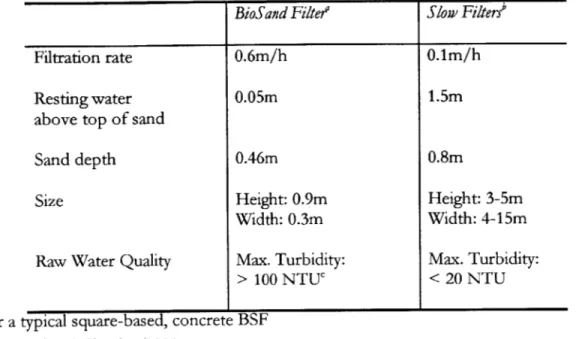
The BSF is a household-scale slow sand filter but with some differences. A typical square concrete BSF is 0.9m tall, and measures 0.30m along its inner edge. A slow sand filter usually has a height ranging from 3-5m and a width of 4-15m (Haarhoff and Cleasby, 1991). The BSF also has a higher flow rate than a typical slow sand filter.The BSF is also different from a slow sand filter with respect to its design to sustain the biofilm during intermittent flow. Two elements of the design contribute to the preservation of the biofilm. First, the filter is designed to hold 5cm of water above the top surface of the sand column while at rest. The 5cm resting water level is based on research performed to determine at what head height the biology receives the maximum oxygen while still being protected from incoming water. A constant aquatic environment is necessary for the organisms present in the layer to survive. However, the water layer cannot be too deep or oxygen will not diffuse and the microorganisms will suffocate. Second, a diffuser plate/basin (see Section 3: Elements of a BioSand filter) blocks input water from disturbing the top layer of sand. (Ritenour, 1998)
Theory
Table 3: Differences between BSF and slow sand filter
BioSand Filte? Slow Filters'
Filtration rate 0.6m/h 0.1m/h
Resting water 0.05m 1.5m
above top of sand
Sand depth 0.46m 0.8m
Size Height: 0.9m Height: 3-5m
Width: 0.3m Width: 4-15m
Raw Water Quality Max. Turbidity: Max. Turbidity:
> 100 NTU < 20 NTU
a For a typical square-based, concrete BSF
b Haarhoff and Cleasby, 1991
, Davnor Water Treatment Technologies Ltd.
2.3
THE SCHMUTZDECKE
Imprecise terminology has contributed to the confusion surrounding proposed particle removal mechanisms in slow sand filters. Particle removal in slow sand filters has been attributed to the schmuttdecke, but the schmutZdecke has been defined in several different ways, including (1) a layer of particles deposited on top of the filter bed (2) biological growth on top of the filter bed (3) biologically active zone within the filter bed. Weber-Shirk and Dick (1997b) proposes using "filter cake" to denote the first two definitions and "biologically active zone" for the third definition so as to avoid confusion. In this thesis, the author uses the terminology consistent with that of Weber-Shirk and Dick.
2.4
BIOLOGICAL REMOVAL MECHANISMS
Biological activity in the sand bed is not well understood. Scientists have a vague idea of the possible processes involved, but specific interactions are still unknown. Suggested biological
removal mechanisms of harmful microorganisms are metabolic breakdown, predation, scavenging, natural death and inactivation (Haarhoff and Cleasby, 1991).
2.4.1
Metabolic breakdown
For many years, the biodegradation of organic matter was thought to be an important biological mechanism in slow sand filter. Huisman and Wood (1974) describe the process as
follows:
"Deposited organic matter is being used as food. The bacteria oxidize part of the food to provide the energy they need for their metabolism (dissimilation), and they convert part of it into cell material for their growth (assimilation). The dissimilation products are carried away by water to be used again at greater depth by other organisms. The assimilation is accompanied by an equivalent dying off. This in turn liberates organic matter, which becomes available to bacteria at lower depths. In this way, the whole of the degradable organic matter present in the raw water is gradually broken down and converted into water, carbon dioxide, and inorganic salts such as sulfates, phosphates, and nitrates to be discharged in the filter effluent."
Experimental studies (Fox et al., 1984) indicated that metabolic breakdown plays only a minor role in the removal of bacteria in slow sand filtration because only a small percentage of the organic carbon is biodegradable. What matters is bacterivory as discussed in the next section.
2.4.2
Bacterivory
Bacterivory is the consumption of bacteria by predators such as protozoa and rotifers. Protozoa are unicellular organisms that ingest their food. Examples of protozoa include
Theory BioSand Household Water Filter Project in Nepal
rhizopods (RhiZopoda) and ciliates (Ciiaphora). Rotifers (Rotatoria) are a group of invertebrates that are distinguished by a crown of moving cilia that draws a vortex of water into the mouth. Two proposed mechanisms by which predators such as protozoa and rotifers may assist in the filtration are (1) predators graze on bacteria and detritus attached to sand grains and (2) predators remove suspended particles as the particles flow through the filter. Predators that graze on attached bacteria potentially free up sites for future bacteria attachment while suspension feeding predators directly remove particles from the mobile phase (Weber-Shirk and Dick, 1998). Recent studies and experiments conclude that while bacterivory is a significant cause of bacterial removal in slow sand filters (Weber-Shirk and Dick, 1997a), it is not the mechanism for removal of larger (>2iim) pathogenic protozoa such as Giardia lamblia and Cryptosporidium oocysts (Weber-Shirk and Dick, 1998).
2.5
PHYSICAL REMOVAL MECHANISMS
Two proposed physical removal mechanisms in a slow sand filter are surface straining and interparticle attraction (or attachment). An experimental-based research to study the physical-chemical mechanisms responsible for particle removal in slow sand filters was recently conducted in Cornell University (Weber-Shirk and Dick, 1997b). Results of the study suggest that straining is the "dominant mechanism of particle removal in slow sand filter cakes where the pore sizes are the smallest", while "inter-particle attraction is primarily responsible for particle removal within the slow sand filter beds".
2.5.1
Surface straining
Surface straining is the "most obvious capture mechanism for particles too large to pass through the interstices between the grains" (Haarhoff and Cleasby, 1991). A tightly packed bed of spherical grains could capture particles about 15% of the grain diameter (Huisman and Theory
Wood, 1974). A clean sand of 200iim effective size is expected to capture particles of about 30 Lm in size by surface straining. This is substantially larger than many particles to be removed from surface water such as cysts (1-20Vtm), bacteria (0.1 to 10tm), viruses (0.01 to 0.1km), and colloidal particles (0.001 to 1 tm) (Haarhoff and Cleasby, 1991). However, larger particles (such as algae and vegetative debris) can be captured by surface straining. As these particles are captured at the surface, the surface pore openings become smaller and surface straining is enhanced, allowing capture of much smaller particles as the filter cake develops. The filter cake, composed of living organisms and other debris from the water, ultimately becomes an effective filtering medium (Cleasby et al., 1984). The filter cake has been described as an extension of the filter bed containing the smallest interstices to achieve the most effective straining (Weber-Shirk and Dick, 1997b). Surface straining was also described as a "sieve effect which is amplified by deposit on the filters' surface of a layer made up of clay, organic matter, algae, and macro- and microorganisms" (Barbier, 1992).
2.5.2 Inter-particle Attraction
Particle attachment to previously removed particles resulting from interparticle attraction can occur in both the filter cake and in the underlying filter bed. Prior to attachment, the particles are transported along flow streamlines unless they are captured by interception or transported across the streamlines causing them to reach a grain surface. If the conditions at the grain surface provide favorable particle-to-grain interaction, attachment will occur.
The efficiency of particle attachment is related to the net attractive force between the medium (consisting of sand and previously removed particles) and suspended particles. Viscous forces hinder attachment or cause detachment by shearing particles from the medium. Shearing forces are expected to be the highest in the filter cake, because shearing forces increase as the Theory BioSand Household Water Filter Project in Nepal
pore size of the medium decreases. Thus, net attachment of particles to previously removed particles because of interparticle attraction may be less efficient in the filter cake than in the underlying filter bed (Weber-Shirk and Dick, 1997).
2.6
FILTER RIPENING
Slow sand filters require a long ripening period at the beginning of each filter run. This is to allow the biology in the sand layer to mature. Filter ripening is a complex process that involves both biological and physical mechanisms. As filtration progresses, biological growth consisting of algae, bacteria, and zooplankton occurs within the sand bed and gravel layer (Bellamy et al., 1985; Graham 1988). During the ripening period, the filter does not effectively remove bacteria. Bellamy et al. (1985) concluded that a new sand bed will remove 85% of the coliform bacteria in the influent. As the sand bed matures biologically, the percent removal
improves to more than 99% for coliform bacteria.
The ripening period for the BSF is usually one to two weeks. However, for slow sand filters, the ripening process can be accelerated by using synthetic polymers (Jellison et al., 2000) to agglomerate particles in the raw water and hasten their removal at the filter surface so as to quickly develop the filter cake. However, the addition of chemicals to the BSF would complicate the originally simple filtration process.
2.7
PREVIOUS BIOSAND FILTER RESULTS
According to the Davnor website, the BSF is effective in removing iron, manganese, sulfur, low concentrations of gases, bacteria, viruses, waterborne parasites, algae, silt and clay (Davnor Water Treatment Technologies Ltd.). The BSF has successfully treated water ranging in temperature from 1* to 45*C. Table 4 summarizes the contaminant removal performance of the BioSand Filter in other countries.
Theory
BioSand Household Water Filter Project in Nepal Theory Table 4: Contaminant Removal Efficiency of BioSand Filter
County OrganiZation Date Contaminant Reported
Removal
(o)
Nicaragua Instituto Nicaraguense de 7/1993 Coliform Bacteria 99.1-99.6Acueductos y Alcantarillados
Canada University of Calgary 11/1995 Fecal Coliform 99.1-99.7
Turbidity 94.1-96.1
Canada National Water Research 11/1996 Heterotrophic 65 - 90+ (
Institute Bacteria Giardia Cysts 99.99 Organic and 50-99.99 Inorganic Toxicants Total Suspended 100 Solids
Total Organic Carbon 14-18 Chemical Oxygen 100 Demand
Vietnam Samaritan's Purse 11/1998 E.coli Bacteria 95.8(2)
Brazil Samaritan's Purse 11/1998 Fecal Coliform 99.7(3)
Bangladesh Proshika Manobik 8/1999 Total Coliforms 99.8 (4)
Unnayan Kendra (river water)
Fecal Coliforms
99.8
(4) (river water)Total Coliform
60-100
(4) (three households)Fecal Coliforms
74.3-100
(4) (three households)Canada Montana Native Reserve Date not Iron 91.5
available Turbidity 85.7
(1) Damage of 10 to 15 % of schmutzdecke discovered at the end of test period (2) Average of 32 households
(3) Average of 21 households
(4) Raw and treated water not tested on the same days.
All samples show zero levels of fecal coliform and minimal levels of total coliform on day of final test
(Source: Davnor Water Treatment Technologies Ltd.)
Theory
3
ELEMENTS OF A BIOSAND FILTER
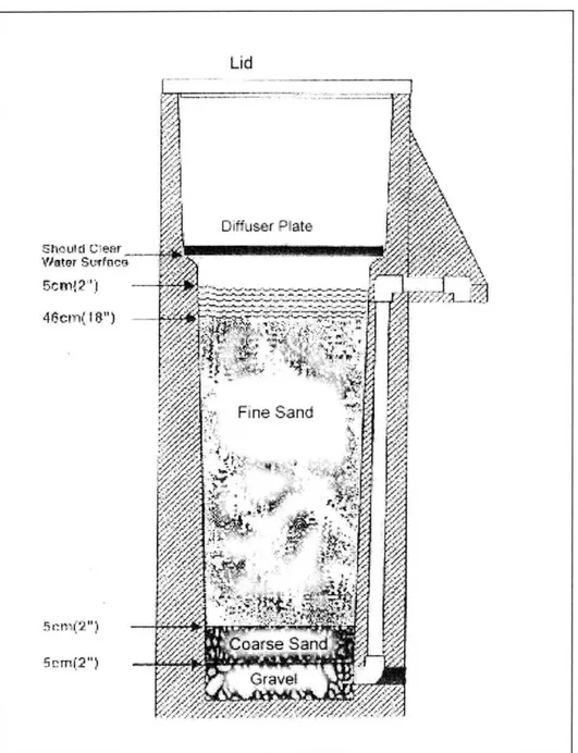
Cross-section of a concrete BioSand Filter is shown in Figure 3. A BSF has several main components:- body/shell, diffuser plate, sand/gravel, and lid. Each of these components will be described in detail in this section.
Figure 3: Cross-section of a concrete BioSand Filter
Lid
Diffuser Plate Shculd Cl~ear Water St;fnec 5rcm 'I c I , I Fie an rSand',
XX
G rave 5 r., n(7')BioSand Household Water Filter Project in Nepal Elements of a BioSand Filter Table 5: BSF Design Parameters
Design Parameter Value
Fine Sand Size <1mm
Coarse Sand Size 1mm - 6mm
Underdrain Gravel Size 6mm - 15mm
Surface Area of Sand 540m2
Initial Flow Rate 1L/min ± 30%
BSF Size 30cm x 30 cm x 90cm
3.1
CONCRETE BODY/SHELL
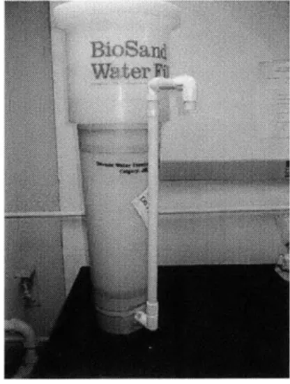
The BSF shell can be made of plastic or concrete. The plastic BSF shown in Figure 4 costs $1252 from Davnor Water Treatment Technologies Ltd., which is about four times the cost of a locally made concrete filter as shown in Figure 5 ($323). Therefore a concrete filter is far more affordable for an average Nepali household.
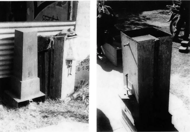
The concrete shell is cast in a steel mold. Casting is carried out on site because transportation over long distances with bumpy road conditions to some of the less accessible places in Nepal might cause damages to the BSF shell (Chettri, 2001a). The concrete BSF can have a square or
round base (Figure 6 and Figure 7).
2 Invoice from Davnor Water Treatment Technologies Ltd for a plastic BSF bought by Lee Hersh, a retired chemist from Cornell University and donated to MIT in Fall 2000.
Elements of a BioSand Filter BioSand Household Water Filter Project in Nepal
BioSand Household Water Filter Project in Nepal Elements of a BioSand Filter
Figure 4: Plastic BSF from Davnor Water Treatment Technologies Ltd.
Figure 6: Concrete BSF with square base.
Figure 5: Concrete BSF made from shop drawings provided by Davnor Water
Treatment Technologies Ltd.
Figure 7: Concrete BSF with round base.
Elements of a BioSand Filter BioSand Household Water Filter Project in Nepal
3.1.1 Riser pipe assembly
Cut the PVC pipe into four sections (Chettri, 2001c) and saw off the edges forming a 450 angle as shown below:
Figure 8: PVC pipe dimensions (not to scale)
9 CM
/ 61cm
jIt
Join the various sections together with glue (IDRC Module 5, 1998). Alternatively, heat join using a flat heating plate.
3.1.2 Preparation of mold
Detailed technical drawings for the steel molds of the concrete version of the BSF are available through Samaritan's Purse or IDRC (IDRC Module 5, 1998). Figure 9 shows the cross section of the steel mold.
BioSand Household Water Filter Project in Nepal Liements of a BioSand Filter
Figure 9: Cross section of inner and outer molds (Ritenour, 1998)
U - a u ~ ~r n Puller Suppedi Pipe Cokinn Clain 8rolt
-I
J Noii'!
I
ift Mo'dI
B
3
C
I
I
a
E'Xrur..
-
wMIMIMwMMwM=;&, - - -I - -- - - 1. - - - - - -- ----&
BioSand Household Water Filter Project in Nepal Elements of a BioSand Filter
Rirser Averve Alser Spiuli Clanp
Scrnw
BioSand Household Water Filter Project in Nepal Elements of a BioSand Filter
Figure 10: Unassembled steel mold - inner mold (left) and outer mold (right).
Figure 11: Steel mold for concrete BSF shell (assembled)
Stand the fully assembled mold upright, base down. Install the riser pipe that was assembled previously inside the outer mold section. Coat the inside of the molds and the clamping bolt with edible oil or lard. This is to prevent the concrete from sticking to the molds.
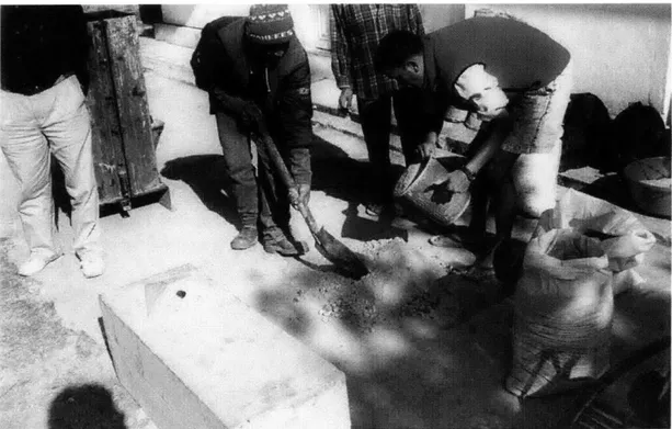
3.1.3 Mixing concrete
Materials required for concrete body:
1. 2. 3. 4. 5. 36 L of cement 36 L of sand 36 L of gravel Water Bucket
Elements of a BioSand Filter
6. Shovel
7. Mixing tray/slab or wheel barrow 8. Steel or wood rod
9. Piece of wood (to use as a trowel)
Concrete is mixed in equal proportion (by volume) in a wheel barrow or on any clean surface. Water is added a little at a time until concrete reaches the proper consistency. The amount of water needed depends on the initial moisture level of the sand and gravel. As a rough guide, take a handful of the final mixture and squeeze it hard. If the consistency is right, it will just be possible to squeeze a few drops of liquid out of the handful.
Figure 12: Concrete Mixing I
BioSand Household Water Filter Project in Nepal Elements of a BioSand Filter
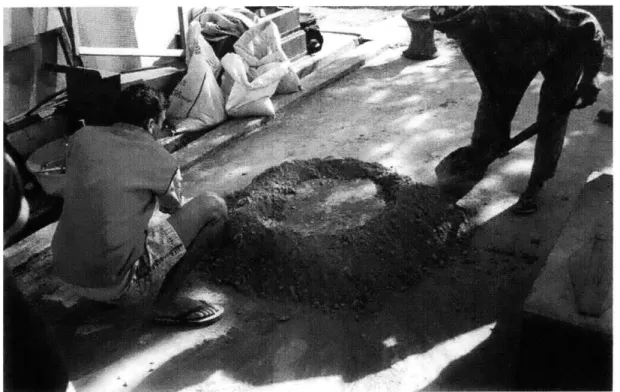
Figure 13: Concrete Mixing II
3.1.4 Concrete Pour
The concrete pour should not be carried out in direct sunlight because the concrete must cure in the shade. These are the procedures for pouring:
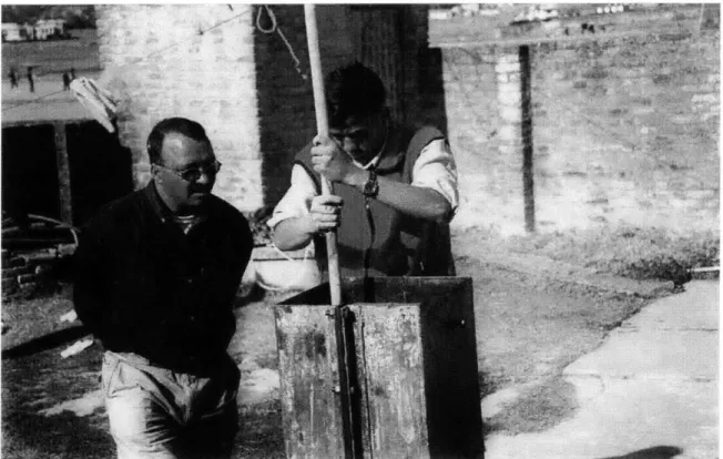
Pour one third of the concrete into the steel mold. Thrust a steel or wooded rod in and out of the concrete and pound the outside of the mold with a rubber mallet to ensure that the concrete fills all sections of the mold and to release any air bubbles. Repeat this procedure twice more, each time pouring a third of the concrete. Prior to completely filling the mold, oil the top portion of the inner mold as some oil will have worn off in the pouring process.
BioSand Household Water Filter Project in Nepal Elements of a BioSand Filter
Figure 14: Tamping the concrete mixture with a wooden rod
Level the top of the concrete surface using a short piece of wood. Adjust the clamping bolt which holds the riser pipe against the inner mold so that there is enough pressure to hold the rise pipe in place without causing the outside mold to deflect on that side. This will leave a hole in the filter wall that will have to be patched later. About fifteen minutes after the concrete is poured, release the concrete clamping bolt.
3.1.5 De-molding Materials required: 1. 2. 3. 4. 5. Mold wrenches About 200g of concrete Pliers Hammer Scrap wood
Elements of a BioSand Filter BioSand Household Water Filter Project in Nepal
Carefully turn the mold right side up (inner mold legs up). Since the mold, now charged with concrete, has an enhanced capacity to smash fingers, set a piece of wood down to avoid setting the mold flat on the ground. Remove the riser pipe clamping-bolt using a wrench. Clean this bolt and its threading nut with a wire brush after each casting.
Place the puller-support in its slots and screw in the threaded rod. The rod only needs to be threaded the depth of the base nut. Once in place, hand tighten the floating nut against the puller-support crossbar. Remove base bolts. Using a wrench, continue to tighten the floating nut against the crossbar to break the inner mold free. Raise it about 5cm. At this point, the inner mold should be sufficiently loose for two people to lift it out by hand. If the inner mold sticks, tap the outer mold with a rubber mallet while tightening the nut. Set the inner mold aside. Remove the nuts and bolts connecting the two sections of the outer mold. Remove the riser pipe spout using a pair of pliers. Remove the pour spout clamp plate and gasket.
Starting with the rear outer mold section, use both hands to slowly pull back on the mold base and remove this section. Pull gently and evenly, avoiding jerking motion. If the mold does not budge, tap the connection edge (where the halves bolt together) using a piece of wood and a hammer, alternating from one side to another. Be careful not to strike the concrete with the hammer and always use a piece of wood. One person should be pulling on the mold while another is tapping. Remove the front section of the mold.
Using some concrete, patch the hole created by the clamping bolt, any cracks that appear, and any other significant imperfections in the concrete. Scrape the rough edges off the filter. These usually occur at the top of the filter and along the two sides where the seam of the outer mold
section was. Scraping should be done while the concrete is still curing.
Elements of a BioSand Filter
Keep the filter wet and out of the sun for 2 to 3 days to allow the concrete to cure properly. Water can be poured in to keep the filter body wet. If it cures too quickly due to sun exposure or a warm, dry wind, cracking may occur. Clean the mold and all its parts. If an even,
debris-free layer of lard or oil remains on the mold, it may be left for the next casting.
3.2
DIFFUSER PLATE
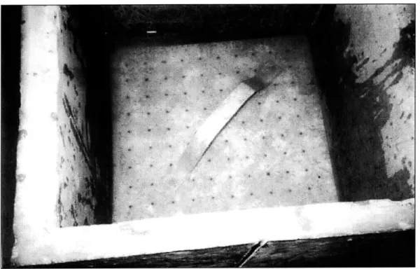
The diffuser plate is a thin plate with 3mm perforations spaced 2cm apart in a square grid. The plate rests on the inner ledge above the resting water level. (see Figure 17). The main function of the diffuser plate/basin is to distribute the fall of the water over the whole filtering surface to avoid damage to the upper sand layer and the destruction of the biological layer (Module 5, 1998). The diffuser plate/basin also serves to sieve the larger impurities carried by the water, such as leaves, branches and larger insects.
3.2.1
Materials
The diffuser plate can be made of various common materials such as metal, wood, or plastic. This flexibility in the choice of materials allows the tailoring of the diffuser plate according to which material is locally available and therefore the lowest cost. In Nepal, most diffuser plates are made of galvanized zinc or plastic. A main criterion for the choice of metal is non-corrosiveness. Figure 15 shows a typical galvanized zinc diffuser plate in Nepal.
Most plastic diffuser plates in Nepal are made of low density polyethylene (LDPE) cutting boards, which are widely available in Nepal and locally known as "Korea plastic" (Magar, 2001) (see Figure 16). The design of the Nepali LDPE diffuser plate owes to the ingenuity of one of the local technicians, Durga Bahadur Ale Magar. He found that the breadth of the cutting board is about the same as the inner edge of the filter. This simplifies the steps to make a diffuser plate to just sawing off the length of the cutting board to make a square. To save Elements of a BioSand Filter BioSand Household Water Filter Project in Nepal
materials, two sawed-off portions are fastened together (with staples or dowel pins) to form
another diffuser plate.
Although wood is another recommended material for diffuser plates (Ritenour, 1998), wooden
diffuser plates were not found in Nepal. The wood to be used must not leach color, shrink,
swell, or warp in water. If color runs out of the wood, it will pass through the filter and
discolor the filtered water. If the wood shrinks or warps, it will not fit tightly against the filter
body and water will skirt its edge, disrupting the top layer of sand.
Figure 15: A typical metal diffuser plate with handle in Nepal
Figure 16: Low Density Polyethylene Plastic (LDPE) diffuser plate in Nepal
3.2.2
Design
There are several designs for a diffuser plate. These include basin, pan, and plate. A basin rests on the top ledge of the concrete body (see Figure 17 and
Figure 18). A basin for a square filter is usually made from three sheets of metal. To increase rigidity, the top edge of the diffuser basin is folded back. For a round filter, aluminum pots have been used as the diffuser basins. If the size of the pot is slightly too small for the concrete, it can hammered to form a bigger one (see Figure 19). Holes are drilled at the base of the diffuser basin.
A pan is like a shallow basin. It rests on the inner ledge of the concrete body. It is made from two sheets of metal- one for the sides and one for the base. To join the metal sheets in both the basin and the pan models, the edges of the metal sheets cannot be soldered since most solders contain lead and other heavy metals, and using lead-free solder is more expensive. Elements of a BioSand Filter BioSand Household Water Filter Project in Nepal
Also, galvanized sheet metal, if used, cannot be welded because of the coating. Therefore, a way to join these sheets is folding the edges back so that the sheets interlock and cannot slide
apart.
Diffuser plates are more common than basins or pans since it requires less material. The plates rest on the inner ledge of the concrete body. The dimensions of the plates must be such that the sheet fits tightly against the inner wall of the filter. For the standard concrete BSF in Nepal, the dimensions of a diffuser plate is approximately 30cm x 30cm x 0.5 - 2.5cm. The diffuser plate should be held down by a piece of rock (that covers as few holes as possible), or two pieces of wood to wedge along the edges of the plate. This will prevent the diffuser plate from dislodging when water is poured in. There should be a handle (see Figure 15) on the diffuser plate for lifting it out of the filter. Again, as few holes as possible should be blocked. A screw in the center as shown in Figure 20 or some wires looped through two of the holes in the opposite corners could be possible alternatives.
Figure 17: Metal diffuser basin I
Elements of a BioSand Filter BioSand Household Water Filter Proj'ect in Nepal
BioSand Household Water Filter Project in Nepal Elements of a BioSand Filter
Figure 18: Metal diffuser basin II
Figure 19: A metal pot used as a diffuser basin in a round BSF
Elements of a BioSand Filter BioSand Household Water Filter Project in Nepal
BioSand Household Water Filter Project in Nepal Elements of a BioSand Filter
Figure 20: A screw to aid lifting the diffuser plate out of the BSF
I1
3.3
SAND AND GRAVEL
Sand porosity is an important factor relative to the formation of the filter cake and the biologically active zone. Sand porosity depends on the size and shape of the grains. It increases with the size of the grains and with the homogeneity of grain size and shape.
High porosity leads to high flow rate and low probabilities of collisions between particles in water and the sand grains. Low porosity will bring about low flow rate and clogging. Therefore, a moderate porosity is required for optimal operation of the BSF. The porosity is small enough to trap particles in the water and large enough to let the water through and allow some room for biological growth.
3.3.1
Requirements
Elements of a BioSand Filter BioSand Household Water Filter Project in Nepal
1. Hard, durable, angular grains free from loam, clay and organic matter. Angular grains decrease porosity and increase resistance to flowing water.
2. An effective diameter (d,0) range of 0.15-0.35mm.
3. A uniformity coefficient (C) of less than 3. Uniformity coefficient is a ratio calculated as the size opening that will just pass 60 percent (by weight) of a representative sample of the filter material divided by the size opening that will just pass 10 percent (by weight) of the same sample (Sims and Slezak, 1991). This implies a fairly narrow range of grain sizes with an almost even distribution between the smallest 10% and the largest 10% and with most of the grains being a size in the middle. This distribution of sizes decreases the porosity of the sand, increasing the surface area per volume and the likelihood of collisions in the top portions of the sand.
3.3.2 Preparation
There are several steps to the preparation of the sand and gravel.
Locating source of gravel and sand
Sand from a crushing operation is pure, clean and relatively uniform in size and shape. It requires the least preparation and is the best possible sand source. In the absence of a manufactured source, it is necessary to locate a natural hillside sand deposit. If there are no other choices, one could use riverbed sand. This is not highly recommended because riverbed sand could be contaminated from animal wastes. In addition, riverbed sand grains are more rounded and smooth (as opposed to angular) in their shape, which decreases the effectiveness in trapping contaminants. Sand from high on a riverbank where there is no visible Elements of a BioSand Filter BioSand Household Water Filter Project in Nepal
Biological quality testing
Each sand source needs to be tested for its biological quality. A sand source that is regularly used should be tested every 6 months. The following is the recommended procedure
(Ritenour, 1998):
1. Boil about 1 liter of the cleanest and purest water available (not distilled, mineral, or chlorinated water) for about 5 minutes.
2. Let the water cool to room temperature
3. Test a sample of this water for microbial contamination. This is used as a control. 4. Add 5g of sand to 100ml of water. Stir to mix, cover and let sit indoors or in the shade
for 12 hours.
5. Decant the water into a clean container.
6. Test a sample of this water for microbial contamination.
The boiled water should show negative results. If it does not, there has been a sampling error or the water was not boiled long enough. Positive results in the water with sand sample means the contamination is coming from the sand. Sand from this sand source is not suitable for use in the filter; however it could be used for the construction of the concrete body. More sand sources should be sought out and tested for biological quality as outlined above until a clean source is found (Ritenour, 1998). Alternatively, the sand could be disinfected by boiling or spread out in the sun (Murcott, 2001).
Sifting
Sifting is required to separate coarse and fine sands from underdrain gravel and larger rocks. A total of three different size screens are needed: 12mm screen for under-drain gravel, 6mm screen for the coarse (or supporting) sand, and 1mm screen for the fine (or filter) sand.
Elements of a BioSand Filter BioSand Household Water Filter Project in Nepal
BioSand Household Water Filter Project in Nepal Elements of a BioSand Filter
Figure 21: Sieves for Sand and Gravel
Cleaning and Flow Rate Test
The sand must be free of dirt, clay fines, and organic matter. Slow sand filters are not back-washed so after the sand is placed in the filter beds, it cannot be cleaned quickly or easily. Therefore, sand must be washed and impurities removed before placement in the filter.
Installing
Gravel and sand are then put into the shell according to the layer heights specified in Figure 3.
3.4 LID
A lid is essential to prevent debris, insects and dirty hands from entering and contaminating the filter. The lid should cover the filter at all times, except when adding water or performing maintenance. The lid may be made out of any material, but it must be clean, must not contain gaps that insects might pass through and should be secure and heavy enough so young children cannot disturb it.
M 71. .R
Of J ;I
If f 4
12MM kreen 17 yldrT UNkr~al< Gn rovel 'ti~i1 ir( rs~
...
44*
LL44j
F I I r I I I I
-Yields Cewr e 'Or supporting) S,# 4
![Figure 2: A schematic of the UNICEF filter, an upflow household slow sand filter (from [Gupta and Chaudhuri, 1992])](https://thumb-eu.123doks.com/thumbv2/123doknet/14166705.473978/21.918.212.706.190.619/figure-schematic-unicef-filter-upflow-household-filter-chaudhuri.webp)