Publisher’s version / Version de l'éditeur:
Vous avez des questions? Nous pouvons vous aider. Pour communiquer directement avec un auteur, consultez
la première page de la revue dans laquelle son article a été publié afin de trouver ses coordonnées. Si vous
Questions? Contact the NRC Publications Archive team at
PublicationsArchive-ArchivesPublications@nrc-cnrc.gc.ca. If you wish to email the authors directly, please see the first page of the publication for their contact information.
https://publications-cnrc.canada.ca/fra/droits
L’accès à ce site Web et l’utilisation de son contenu sont assujettis aux conditions présentées dans le site LISEZ CES CONDITIONS ATTENTIVEMENT AVANT D’UTILISER CE SITE WEB.
7th International Conference and Exhibition on Performance of Ships and
Structures in Ice [Proceedings], 2006
READ THESE TERMS AND CONDITIONS CAREFULLY BEFORE USING THIS WEBSITE.
https://nrc-publications.canada.ca/eng/copyright
NRC Publications Archive Record / Notice des Archives des publications du CNRC :
https://nrc-publications.canada.ca/eng/view/object/?id=8cef5a21-50da-484a-842a-2dbcafbe7ef3
https://publications-cnrc.canada.ca/fra/voir/objet/?id=8cef5a21-50da-484a-842a-2dbcafbe7ef3
NRC Publications Archive
Archives des publications du CNRC
This publication could be one of several versions: author’s original, accepted manuscript or the publisher’s version. / La version de cette publication peut être l’une des suivantes : la version prépublication de l’auteur, la version acceptée du manuscrit ou la version de l’éditeur.
Access and use of this website and the material on it are subject to the Terms and Conditions set forth at
Hull form design for icebreaking tankers
Hull Form Designs For Icebreaking Tankers
Hyun-Soo Kim, Mun-Keun Ha,
Dang Ahn
Samsung Heavy Industries, Marine Research Institute,
Koje Shipyard, Korea
hs-john.kim@samsung.com
and
David Molyneux
Institute for Ocean Technology, National Research Council, Canada
David.Molyneux@nrc-cnrc.gc.ca
ABSTRACT
This paper discusses four designs for icebreaking tankers that have been developed by Samsung Heavy Industries and tested at NRC’s Institute for Ocean Technology (IOT). Three of the designs developed were twin-screw ships (with twin rudders). The first two bow shapes were similar to existing Canadian icebreakers. The third ship had a spoon shaped bow designed for heavy ice conditions. The fourth ship was designed for light to moderate ice conditions. The propulsion system for this ship was a single screw, single rudder stern with an innovative bulbous bow. This unique bow design showed considerable improvement in icebreaking performance compared to a conventional open-water bulbous bow but with almost no penalty to open water resistance. The paper presents predictions of speed and power for each icebreaking tanker design, in level ice, pack ice and open water. The important features of each hull form and propulsion system combination are discussed and the most appropriate voyage profile for each design is presented.
INTRODUCTION
Icebreaking ships have become a specialized niche within naval architecture and shipbuilding over the last one hundred years. These ships have typically fallen into the categories of either transportation or support for navigation and offshore oil operation. Within the support category, the ships typically have large propulsion systems in relation to their overall dimensions, similar to a tug. Manoeuvrability for this type of ship is an important criterion, as they have to operate in close proximity to other ships or fixed installations, but their transportation capacity is limited. Ships in this category are typically government-operated icebreakers or commercial offshore supply ships.
The other category of ships requires the modification of typical bulk
America, development of this type of ship has focused on Arctic and sub-Arctic ice conditions, since northern Canada has extensive mineral reserves. The first example of this type of ship in North America was the oil tanker ‘Manhattan’, which made two attempts at sailing through the Northwest Passage in 1969 and 1970 (Gray and Maybourne, 1981). At the time it was built ‘Manhattan’ was the most powerful tanker in the world, with twin steam turbine powered propellers. The original bow was replaced with a long raked bow, which was radical at the time, but has since become a feature typical of icebreakers. The modifications were carried out to ensure that the ship could navigate the Northwest Passage, and no attention was paid to the changes that increased power in open water. Many of the features incorporated into the ‘Manhattan’ are still considered necessary in modern designs.
Another well-documented bulk carrier that was purpose built for operation in ice is the ‘Arctic’ (Luce, 1990). It was powered by a diesel engine driving a single controllable pitch propeller with a nozzle. The original icebreaking bow was replaced in the mid 1980’s but again the emphasis on the new design was for lower icebreaking resistance, although some attention was paid to seakeeping behaviour. The operating experience gained from this ship has been incorporated into the latest generation of Arctic Class bulk carriers, such as ‘Umiak’ to be operated by Fednav from northern Labrador to Quebec City. (www.fednav.com).
The most recent developments in icebreaking merchant ship designs have occurred for ships in Baltic ice conditions. The Double Acting Tankers ‘Tempera’ and ‘Mastera’ (Juurmaa et al., 2002) provide an innovative approach to powering a ship that operates in ice and open water. In these ships, a single azipod unit provides the propulsion force. For operation in open water, the ship has a conventional bulbous bow with the propeller at the stern. For operation in ice, the azipod is reversed, so that the propeller extends under the unbroken ice sheet and the ship breaks ice going astern.
Samsung Heavy Industries has also been successful in providing ships for operation in the Baltic Sea (Kim et al., 2005). So far, these have been modifications to conventional bulk carriers, with little distortion to the shape of the hull for operation in ice.
The approaches chosen in the design of each of the ships discussed above highlights the challenges for ships operating in ice. To be commercially competitive, the design has to be as close as possible to conventional commercial practice, but with sufficient margins of power and strength to provide safe and predictable services for clients.
In 1997, Samsung Heavy Industries initiated a collaborative research agreement with the National Research Council’s Institute for Ocean Technology (formerly Institute for Marine Dynamics). Specific projects covered the development of three concept designs for ice-capable tankers (with some changes in the details of each concept) over the period from 1997 to 2005. This paper presents a summary of the results of these projects, with a focus on powering performance predictions in different ice conditions.
HULL FORM DEVELOPMENT FOR ICEBREAKING TANKERS
Aframax Size, Moderate to Heavy Ice Conditions
The first designs developed by SHI to be tested at IOT were for Aframax sized tankers, operating on a hypothetical route between the Pechora Sea (northern Russia) and Western Europe. The ship was required to move steadily forward in first year ice, with a thickness between one and two metres. The maximum flexural strength of the ice was expected to be approximately 500 kPa. The ship was required to progress at 4 knots in level ice, 1.0m thick, and maintain forward motion in ice 2.0m thick. The design must also be able to transit ridges and move forward in snow-covered ice. The design speed in open water was 16 knots. This mission profile imposed constraints on length, beam and draft. The resulting design had a displacement of approximately 100K tonnes, which was comparable to a typical Aframax tanker. The bow and stern for the second of the two designs are shown in Figures 1 and 2 respectively.
Figure 1, R-class style bow for Aframax sized tanker designed for moderate to heavy ice.
Figure 2, Twin gondola stern for Aframax sized tanker designed for moderate to heavy ice.
The shallow draft that was necessary for this route had an important effect on the powering performance since it restricted propeller diameter and clearance between the propeller blade tip and the hull. This constraint in turn limited the maximum delivered power. The final stern arrangement selected was a twin screw/twin skeg/twin rudder design. This incorporated the requirements for the general arrangement and restricted propeller diameter. It also provided protection for the propellers in heavy ice conditions.
The initial bow shape was developed from the R-Class Icebreaker bows used by Canadian Coast Guard. This bow was considered to have good icebreaking performance, and acceptable performance in open water (Edwards et al, 1981, Michailidis and Murdey, 1981). Two hull shapes were modelled and tested within this basic concept. The initial design concept had acceptable open water powering performance, but in level ice, large numbers of ice pieces were flowing through the propellers, and reducing the propulsive efficiency. The first design was modified in an attempt to improve ice clearing and deflect the broken ice away from the propellers. Ha et al. (1999) gave a detailed description of the hull shapes for the two designs.
Suezmax Size, Moderate to Heavy Ice Conditions
Aframax size tankers are relatively small and as a result can operate on flexible trading patterns. However, the restricted displacement is a limitation for some ship owners. The next design development was to produce an icebreaking tanker of a similar size to a Suezmax design (150K tonnes). The length and beam for the Suezmax design were similar to the initial designs described above, but the draft restriction was relaxed, to a design load draft of 16.5m. The resulting displacement was approximately 160K tonnes.
As a result of the increased draft, the propellers could be placed further away from the broken ice pieces by lowering the line of the propeller shaft. This had the hydrodynamic advantages of increasing the propeller diameter, resulting in a more efficient propeller in open water, and reducing the need for protecting the propellers from the broken ice pieces, which in turn lowered the wetted surface area of the hull and the appendages. The resulting stern design was twin screw/twin rudder, but with simple bossings supporting the propeller shafts, rather than the more complex skegs used for the Aframax size tanker. The stern for the Suezmax size tanker is shown in Figure 3.
Figure 3, Twin propeller shafts and rudders, Suezmax sized tanker designed for moderate to heavy ice
Figure 4, Spoon bow, Suezmax sized tanker designed for moderate to heavy ice
The bow shape was radically different from the Suezmax size tanker. For this design a sloping spoon bow was chosen, similar to the bows developed for the icebreaking supply boats used in the Beaufort Sea. The bow shape is shown in Figure 4.
Suezmax Size, Light Ice Conditions
During the course of the relationship between SHI and IOT, the amount of oil being shipped in and out of Russia, through the Baltic Sea, increased significantly. As a result, SHI’s interest shifted to include ice-strengthened tankers that were designed for Baltic ice conditions because ship sales in that market expanded considerably in 2004. Such designs would have to place more importance on open water performance than the Arctic tankers. These ships were anticipated to spend most of the winter voyage in open water, with relative short portions of time in Baltic ice. These ice conditions are typified by level, unbroken first year ice, and an ice-covered channel created by an icebreaker or other shipping.
In order to explore the performance characteristics of ship designs in this type of ice condition estimates of the powering requirement of conventional hulls in pack ice were prepared. A tanker design tested at IOT for resistance in pack ice (Murray and Spencer, 1996) was initially used. These results were combined with the open water performance of a conventional, single screw tanker designed and tested by SHI. The bow and stern of the conventional tanker are
Figure 5, Stern arrangement for conventional tanker
Figure 6, Bulbous bow for conventional tanker
In addition to estimates of the powering of a conventional tanker, a design was developed for a bulbous bow tanker, which would have open water performance as good as a conventional tanker, but with lower powering requirements than the conventional tanker in pack ice and light ice conditions. Two iterations were carried out on this design.
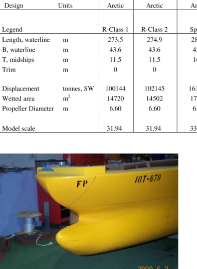
To be competitive with conventional tanker design, the stern of this hull was to be fitted with a single screw and a single rudder. The stern arrangement for the ice capable tanker is shown in Figure 7. The bow for this design was a modified bulb, which at the design draft was much lower in the water than a conventional bulbous bow. The hull above the bow was heavily flared, so that the resulting shape was similar to the spoon bow discussed above. The underside of the bulb was also flared to provide some ice breaking capability at the ballast draft. A picture of the bow is given in Figure 8. Table 1 gives a summary of the principal particulars for each ship, and the scale of the model.
Table 1, Summary of Principal Dimensions Design Units Aframax Arctic Aframax Arctic Suezmax, Arctic Suezmax Conventional Suezmax Baltic
Legend R-Class 1 R-Class 2 Spoon
Open water bulb
Ice bulb & Modified ice bulb Length, waterline m 273.5 274.9 284.0 258.3 271.48 B, waterline m 43.6 43.6 42.8 46.2 44.0 T, midships m 11.5 11.5 16.5 16.6 15.0 Trim m 0 0 0 0 0 Displacement tonnes, SW 100144 102145 161935 162001 145699 Wetted area m2 14720 14502 17689 17492 16746 Propeller Diameter m 6.60 6.60 6.72 9.80 8.10 Model scale 31.94 31.94 33.87 44.55 36.82
Figure 8, Modified bulbous bow for ice, Suezmax sized tanker designed for operation in light ice
MODEL TEST METHODS & SCALING
Obtaining accurate predictions of ship powering performance in ice continues to be a technical challenge. Several published methods of predicting resistance in ice were reviewed as part of this project (Kim et al, 1999). The variation between the results of different prediction methods was too broad for any analysis beyond very preliminary design studies. As a result, model experiments were the only practical option for providing the data needed for design evaluation. All of the icebreaking tanker designs were evaluated at model scale in the Ice Tank at IOT, which was 80m long, 12m wide and 3m deep.
Modeling Ship Performance in Open Water
Prior to carrying out experiments in ice, open water resistance experiments were carried out. These experiments were required to provide the open water resistance component of the total resistance in ice, and to provide baseline data on the resistance of the hull. The experiments were carried out on the appended model (with rudders, ice knives and propeller fairing cones) over a range of speeds from 2 to 18 knots in IOT’s Ice Tank.
These experiments followed normal towing tank practice for obtaining open water resistance predictions, except that turbulence
stimulators were omitted. Ship predictions were obtained using the 1957 ITTC model-ship correlation line, with a correlation allowance (Ca) of 0.000.
Modeling Ship Performance in Level Ice
The EGADS (CD) model ice prepared in the ice tank at IOT has been developed to provide the kinematic and mechanical characteristics required to model the ship-ice interaction correctly. The ice is grown at finely controlled temperature in a mild EGADS solution resulting in uniform thickness, with standard deviation normally less than 3%. Fine bubbles are selectively incorporated into the ice to produce the required ice density and plate stiffness. The ice is tempered for a period of time before the test, until the required flexural strength is achieved. Shear strength and compressive failure stresses are established as functions of the flexural strength, similar to the full scale relationships.
Ice flexural strength was measured using cantilever beam tests at different times and locations in the tank. Ice thickness was measured every two metres along the ship track after a test. Ice density, shear strength, and compressive failure stress were determined from flexural strength relations, calibrated by measurements in each ice sheet. Pack ice concentration was determined from digitized overhead photographs of each ice sheet. The ship-ice friction coefficient was measured and verified for each ice thickness in the test program. The coefficient was determined between a sample of ice from the tank at test time and a flat horizontal surface finished simultaneously with the ship model final surface.
Pack ice was prepared by breaking the ice sheet into approximately uniform floes and distributing the floes evenly over the test area. Photographs of the pack ice were taken and analyzed to estimate the concentration of ice within the test area. Two concentrations of pack ice were used in this project (95% and 75% nominal values). Additional ice conditions were prepared (for the bulbous bow design only) from the level ice sheets. Brash ice was prepared on the centerline of the ice tank, by cutting a channel with straight edges. The ice broken ice was evenly distributed over the channel. Nominal concentration within the channel was 90 to 100%. This required compacting the ice so that the final length of brash ice
was less than the length of the un-broken ice sheet. Photographs of the brash ice were taken and analyzed to estimate the concentration of ice within the channel. Two channel widths were used in this project (120%B and 200%B, where B is the beam of the ship). IOT’s method for carrying out resistance experiments in ice is given by Spencer and Jones (2001). It assumes that four different forces occur when a ship moves through ice. These forces are due to breaking the ice, the movement of the ice pieces around the hull, the friction of the ice against the hull, and the open water resistance (which is itself probably modified by the presence of the ice). These forces all scale differently to full-scale. Tests are conducted in open water, in level ice, and in pre-sawn ice in order to determine the resistance due to the different processes. Also, by using non-dimensional coefficients, it is easy to extrapolate the results to full-scale. The resulting force components are scaled from model to full scale by λ3, where λ is the linear scale of the
model, except for the open water resistance, which includes a viscous scaling factor based on the ITTC 1957 line.
Modeling Ship Performance in Pack Ice
A method for analyzing the results of resistance in pack ice has been presented by Colbourne (2000), which considers only the buoyancy and submergence forces caused by the ice on the ship’s hull. This method is the same as the analysis of the pre-sawn resistance component used in level ice resistance analysis, with the addition of an ice concentration component. For pre-sawn ice (100% concentration) this factor has a value of 1.0.
In the analysis of level ice resistance it was assumed that there were four force components, all of which scale separately. In the case of resistance in pack ice, provided that the flow sizes are small, the ice breaking forces can be ignored. Resistance forces on a ship model due to pack ice are determined by subtracting the hydrodynamic resistance, determined from the open water experiments, from the total measured resistance.
Colbourne (2000) recommended a value of 3 for n in the formula for non-dimensional resistance in pack ice, based on data for speeds appropriate for moored ships or FPSOs, where the only flow component was caused by a current. Analysis of the arctic tanker data for SHI, together with other ships tested in pre-sawn ice and pack ice, suggests a value of 2 collapses pack ice and presawn ice resistance onto a single line, with the smallest error band.
Predicting Delivered Power in Ice
The principle of IOT’s method for predicting delivered power in ice is that overload experiments in open water can be used to predict the hydrodynamic torque required to develop a thrust sufficient to move the hull against a force equal to the hull resistance in ice. Because such open water tests cannot take account of any ice-propeller interaction, it is necessary to conduct a corresponding experiment in ice to determine the increase in torque due to propeller-ice interaction. It is assumed in this method that propeller-ice interaction has a negligible effect on the thrust developed by the propulsion system. This has been shown to be true for small values of hi/D where hi is the ice thickness and
D is the diameter of the propeller. The torque due to ice is considered a function of the ice parameters (thickness, strength etc.) and added to the open water values. This method is applicable to all types of ice, provided overload experiments in open water are carried out over a range of propeller rotations applicable to each ice condition.
This method has the practical advantage that because the towing carriage arrangement for resistance in ice and overload propulsion in ice tests are identical it is possible to quickly change from one to the other. Thus, resistance and propulsion experiments in the same ice sheet are possible without unacceptable deterioration in the properties of the ice.
For overload experiments in open water the model is towed, as in resistance experiments, but with the propellers operating. The range of interest was ice-breaking speeds from zero to 8 knots. Thrust, torque and revolutions were measured on each shaft, together with model resistance, which for low speeds and high delivered power was a towrope pull. Five different rates of shaft revolutions up to approximately maximum delivered power for the ship were tested at each forward speed. Measured torques were corrected to the value at the propeller by carrying out experiments before and after the propulsion experiments to determine the mechanical friction in the stern tube bearings.
Self-propulsion experiments in ice using an overload method were conducted in a similar manner to open water experiments. It was not necessary to predict exactly the ship self-propulsion point, but the experiment was carried out at a rate of propeller rotation as close to that point as possible. The required rate of shaft rotation was estimated from the results of the resistance in ice experiments and the open water overload experiments by equating the tow force to the resistance in ice. The shaft revolutions were set and the model was towed through the ice sheet. Values of thrust and torque in ice were measured on each shaft, together with tow force and shaft revolutions. The total torque was analyzed to determine the mean value for each ice condition, relative to the open water value determined above.
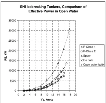
COMPARISON OF POWERING PERFORMANCE Effective Power in Open water
A useful index of ship performance in open water is effective power. This is the product of the resistance of the hull, in Newtons and the speed of the hull in metres per second. Effective power has Watts as a unit and is typically plotted against ship speed in knots. Effective power is the power needed to pull the model through the water.
Effective power is plotted against ship speed in Figure 9 for five of the designs. There was no observable difference between the Ice bulb and the Modified ice bulb, so only one of the icebreaking bulbous bow designs is shown.
The important features of this graph are that:
i) The lowest effective power was for the Aframax
designs (R-Class 1 and R-class 2), which had the smallest displacements and smallest wetted surface areas.
ii) The bulbous bow design for the Baltic tanker (Ice bulb) met its performance objective of having the same effective power as the conventional open water bulb.
iii) The spoon bow had effective power that was 200%
of the bulbous bow designs at 12 knots and 180% at 16 knots. The spoon bow will have very high powering requirements in open water, and as a result, will not be suitable for long voyages where no ice is present.
Figure 9, Comparison of effective power in open water
Resistance and Propulsion in Level Ice
The predicted resistance in level ice, for the four ice breaking tankers is shown in Figures 10 and 11. All of the results have been presented for a hull-ice coefficient of 0.05, which IOT considers to be the average value for a freshly painted new ship in ice with minimal snow cover. The two ice thicknesses presented are 0.75m and 1.4m, which represented average and extreme conditions for Baltic Ice. The 1.4m thickness also represented an average condition for Arctic ice. In all cases the results are presented for a flexural strength of 500 kPa.
Figure 10 shows that for 0.75m ice, the Aframax designs (R-Class 1 and 2) have the lowest resistance, followed by the spoon bow and the bulbous bow has the highest resistance, but is only 50% higher than the spoon bow. Figure 11 shows that as the ice thickness is increased, the difference between the designs becomes more pronounced, but the ranking does not change.
If resistance magnitude is considered to be the design point (which is roughly equivalent to the thrust needed from the propeller to move the ship), then the same thrust to move the spoon bow at 6 knots would move the bulbous bow at 4 knots in 0.75m of ice. This is encouraging, since it is likely that the bulbous bow will be able to make forward progress. Similar trends can be seen from the results in 1.4m of ice.
The hulls with bulbous bows had much higher resistance in ice than a conventional icebreaker shapes. From observations of the ice fracture behaviour and the movement of the broken ice pieces during the experiments (including underwater video records) the high resistance was caused by secondary breaking of the ice floes on the upper surface of the bulb. The initial design was modified to include a higher slope between the waterline and the top surface of the bulb and retested. The changes to the design reduced the delivered power in 0.75m of ice by 20% at 6 knots, without having any effect on the open water resistance.
Figure 10, Comparison of resistance in level ice, Hi=0.75 m, µ=0.05
Figure 11, Comparison of resistance in level ice, Hi=1.4 m, µ=0.05
Resistance and effective power are not the best measure of ship performance. The ship has to be propelled, which introduces additional hydrodynamic interactions between the hull and the propellers. The magnitude of the interaction effect is different between single and twin propellers. A twin-screw ship typically has lower values of wake fraction than a single screw ship, since the propellers are further away from the hull, and the flow is closer to the free stream speed. Also, a twin-screw propulsion system has a lower loading per propeller than a single screw system. This will mean that the propellers are less likely to cavitate, and propeller diameter can be smaller than if the same total amount of power has to be delivered to a single screw. The results of self-propulsion experiments are required to determine the level of the hull-propeller interaction and predict the power needed to drive the ship.
Resistance in level ice, 0.75m thick, mu=0.05
0 500 1000 1500 2000 2500 3000 3500 4000 0 1 2 3 4 5 6 7 V, knots R i, k N R-Class 1 R-Class 2 Spoon Ice bulb
Resistance in level ice, 1.40 m thick, mu=0.05
0.0 1000.0 2000.0 3000.0 4000.0 5000.0 6000.0 7000.0 0 1 2 3 4 5 6 7 V, knots R i, k N R-Class 1 R-Class 2 Spoon Ice bulb
SHI Icebreaking Tankers, Comparison of Effective Power in Open Water
0 5000 10000 15000 20000 25000 30000 35000 0 2 4 6 8 10 12 14 16 18 20 Vs, knots P E , k W R-Class 1 R-Class 2 Spoon Ice bulb Open water bulb
Predictions of delivered power in level ice, 1.0m thick are given in Figure 12. These figures show that the ranking of the designs is the same as the results of the resistance experiments, with the two Aframax vessels having the lowest power requirement and the bulbous bow design having the highest. Based on these predictions, it is unlikely that the bulbous bow design would be able to move forward in level ice at two knots with less than 20MW of delivered power, which is 30% higher than the typical power for a Suezmax design for operation in open water only. Designing a propeller for icebreaking speeds is a challenge, since the advance ratio (J=Va/nD) is very low, and screw propellers have inherently low efficiency in this region. As a result, propulsive efficiency in ice is low, compared to values in open water.
Figure 12, Comparison of delivered power in level ice, Hi=1.0 m, µ=0.05
Self-propulsion experiments in ice are complicated by the additional interaction between the broken ice pieces flowing around the hull and into the propeller. The ice flow through the propeller increases the torque, relative to the torque at the same rate of propeller rotation in open water and in thick ice it can also reduce the thrust. A simple measure of the level of propeller-ice interaction (Molyneux et al., 1990) is the ratio of mean torque in ice to mean torque in open water. The average values for the four designs (across all speeds and ice thicknesses tested) are given in Table 2.
Table 2, Ratio of propeller torque in ice to propeller torque in open water Model Qi/Qo R-Class 1 1.15 R-Class 2 1.25 Spoon 1.08 Ice bulb 1.00
Twin-screw hulls have the advantage of distributing power to two shafts but the disadvantage is that propellers are more exposed.
protect the propellers of a shallow draft ship from ice pieces that flowed around the hull. The resulting high ratio of torque in ice to torque in open water was due to a large amount of ice flowing around the hull and into the propeller as a direct result of the shallow draft. Also, large ice floes broken by the hull at the bow could become jammed between the gondolas. Less protection was needed for the Suezmax size tanker, since the propellers were further away from the ice surface, due to the deeper draft. The result was that the ratio of Qi/Qo ratio was lower than for the Aframax designs. The bulbous bow was very effective at deflecting the ice away from propeller. No propeller ice interaction was observed for any of the speeds or ice thicknesses tested.
Pack Ice
It is also important to compare performance of ships in broken ice, especially if the ship is going to operate in areas such as the Baltic Sea. Predictions of resistance against speed for each ship in pack ice, 0.75m thick with a concentration of 95% (area of ice cover relative to total area) are given in Figure 13. The results show little effect of bow shape on resistance between the icebreaker bows. In broken ice, the performance of the bulbous bow designs relative to the icebreaker bows is better than in level ice. In broken ice there is much less tendency to submerge the ice floes, so as a result, there is much less secondary breaking. Although resistance for the bulbous bow design is about 40% higher than the icebreaker bows, it is approximately half the resistance of the conventional tanker.
Figure 13, Resistance in 0.75m pack ice, 90% concentration
Delivered power in pack ice against speed for three of the designs are plotted in Figure 14. These predictions show that a hull with a bulbous bow can have as good or better delivered power requirement in pack ice than a hull with a conventional icebreaker bow (for speeds below 5 knots). This is due to the fact that although the resistance is higher, there is no torque increase due to contact with the broken ice pieces. As a result, the delivered power is lower than the spoon bow icebreaker.
The early models developed during these projects (R-Class 1 & 2) were not tested over a propeller rotation rate range low enough for good predictions of powering in pack ice. For this reason they have been omitted. It is likely that they that they would be worse than the spoon bow, since there was little difference in resistance, but propeller-ice interaction will be even higher, as a result SHI Tankers,
Delivered power in ice, 1.0m thick, 500 kPa, mu=0.05
0 5000 10000 15000 20000 25000 30000 35000 40000 45000 50000 0.00 1.00 2.00 3.00 4.00 5.00 6.00 7.00 8.00 V, knots P E , P D , k W R-Class 1 R-Class 2 Spoon Ice bulb
Resistance in pack ice
0.0 500.0 1000.0 1500.0 2000.0 2500.0 3000.0 4.00 5.00 6.00 7.00 8.00 V, knots R t, k N
Open water bulb R-Class 1 R-Class 2 Spoon Ice bulb
Figure 14, Delivered power in pack ice
VOYAGE PROFILE ANALYSIS
The collaborative project between SHI and IOT resulted in three distinct design concepts. Each one had its strengths and weaknesses. It is not valid to compare the ship performance in individual ice conditions, since a particular ship must spend time in a variety of ice conditions. An ‘average’ performance over the expected range of operating conditions is a better means of comparison.
A simple method of comparing the effectiveness of different designs over different ice conditions is to use a weighting function, based on the delivered power required for each design in each ice condition. In mathematical terms the weighting function is expressed as
=
i i iT
Pd
t
W
Whereti is the time in the ice condition
Pdi is the delivered power in the ice condition
T is the total time of voyage
i is the number of ice conditions
For the purposes of this paper, the hypothetical ship speed and ice conditions were:
i) 16 knots ship speed in open water
ii) 6 knots ship speed in pack ice, 1m thick with 95%
concentration
iii) 4 knots ship speed in level uniform ice, 1m thick with a flexural strength of 500 kPa
These conditions were picked since the environmental parameters were covered within all of the model test programs carried out as part of the collaborative agreement. They do not correspond to a particular route, but the method can be expanded to include more
ice conditions, provided the expected period of time in each ice condition are known.
Three examples are presented in this paper for discussion purposes. These were based on the time distributions given in Table 3. The results are shown in Figures 15 to 17.
Table 3, Time distributions for three voyage scenarios
Scenario Open water ti /T Pack ice ti /T Level ice ti /T Light ice 0.90 0.05 0.05 Moderate ice 0.50 0.25 0.25 Heavy ice 0.25 0.375 0.375
The ships compared were one of the Aframax designs (R-Class 2) and two of the Suezmax designs, one for moderate to heavy ice (Spoon) and one of light ice (Modified ice bulb). In all scenarios, the Aframax design has the lowest value of W, but it should be pointed out that this ship is smaller than the other two designs. In the light ice scenario, the bulbous bow design has a much lower index than the moderate to heavy ice design. The ratio of the two indices was 1.72. In this scenario the relatively poor open water performance of the spoon bow is dominating the value of the total index. As the amount of time spent by each design in ice increases, then the disadvantage of the poor open water performance becomes less critical. In the moderate ice condition, the ratio of the two indices dropped to 1.20 and for the heavy ice, the spoon bow shape is the best, and the ratio has dropped further to 0.94. This is a very simple performance index, but it illustrates how critical open water performance is to the overall fuel consumption of any icebreaker design.
CONCLUSIONS
The results of this research have been extremely important to SHI’s strategy to become the world leader in the construction of large icebreaking merchant ships. Model testing has been an essential element of this strategy, since it is the opinion of the authors that analytical methods are not sufficiently well developed for accurate performance predictions. The results of the research have shown that:
1) Quite different bow shapes can result in similar resistance in ice, once allowances for hull-ice friction coefficient and ice thickness have been included.
2) Icebreaker designs have the lowest resistance in level ice and pack ice. Such a design is characterized by a raked bow with a long overhang. This type of bow is effective at breaking the ice, and directing the broken pieces around the hull. However, this type of bow has relatively poor performance in open water. 3) Bulbous bows in ice have distinctive properties, compared to conventional icebreaker bows. The bow shape results in a lot of secondary breaking where the ice floes come into contact with the upper surface of the bulb. When the ice is already broken before it comes into contact with the ship, this penalty is removed. It is possible for a ship with a bulbous bow to be effective in light ice conditions, especially pack ice. The ice breaking performance Comparison of effective and delivered power
in pack ice, 1.0m thick, 95% concentration
0 5000 10000 15000 20000 25000 30000 35000 40000 0.0 2.0 4.0 6.0 8.0 10.0 V, knots P D , k W Spoon Ice bulb Modified ice bulb
is clearly much worse than a bow designed for heavy ice, but the improvement in open water performance compensates for this. It may be particularly effective in an area with extensive icebreaker support.
ACKNOWLEDGEMENTS
The authors would like to thank the management of Samsung Heavy Industries and the Institute for Ocean Technology for permission to publish the results of this research. They would also like to thank the many staff at IOT who worked on these projects constructing models, preparing them for testing and carrying out the model experiments.
REFERENCES
Colbourne, D. B. 2000 ‘Scaling Pack Ice and Iceberg Loads on Moored Ship Shapes’, Oceanic Engineering International, Vol. 4. No. 1, pp 39-45.
Edwards, R. Y., Dunne, M. A. and Johnson, B. 1981 ‘Results of Full-scale Trials in Ice on CCGS Pierre Raddison’, STAR
Symposium, SNAME, pp 291-310.
Gray, W. O and Maybourne, R. 1981 ‘Manhattan’s Arctic Adventure- A Semi-technical History’, Paper 1, STAR
Symposium, SNAME.
Ha, M-K, Kim, H-S, Ahn, D., Williams, F-M and Molyneux, D. 1999 ‘Development of an Arctic Tanker Design’, 18th
Offshore Mechanics and Arctic Engineering Conference (OMAE), St. John’s.
Juurmaa, K., Mattson, T., Sasaki, N. and Wilkman, G. 2002 ‘The Development of the Double Acting Tanker for Ice Operation’,
Okhotsk Sea and Sea Ice Conference, Mombetsu, Japan, 24-28th February.
Kim, H-S, Ha, M-K, Ahn, D., Molyneux, D. and Chun, H-H., 2002 ‘Hull Forms for Icebreaking Tankers’, 23rd Offshore Mechanics and Arctic Engineering Conference (OMAE), Vancouver.
Kim, H-S, Ha, M-K, Ahn, D., Kim S-H and Park, J-W. 2005 ‘Development of 115K Tanker Adopting Baltic Ice Class 1A’,
International Offshore & Polar Engineering Conference (ISOPE), Seoul.
Luce, M. P. ‘Experience Gained From the Upgrading of the Bow of the M. V. Arctic’, 1990, Icetech 90, Paper K, Calgary. Michailidis, M. and Murdey, D. C. 1981 ‘Performance of CCGS
Franklin in Lake Melville 1980’, STAR Symposium, SNAME, Ottawa, pp311-322.
Molyneux, W. D., Simoes-Re, A-J, Spencer, D. and Reynolds, A. 1990 ‘Recent Developments in Model Experiment Techniques for Large Icebreakers’, Icetech 90, Paper E, Calgary.
Murray, J. J. and Spencer, D. 1996 ‘Preliminary Investigations into Mooring Forces on a Semisubmersible and a Turret Moored Tanker in Pack Ice, Current and Waves’, 15th Annual Conference on Offshore Mechanics and Arctic Engineering (OMAE), Florence.
Spencer, D. and Jones, S. J. ‘Model Scale /Full Scale Correlation in Open Water and Ice for Canadian Coast Guard “R-Class” Icebreaker’, 1996, J. Ship Research, Vol. 45, No. 4, pp249-261
Figure 15, Comparison of performance index, light ice scenario
Figure 16, Comparison of performance index, moderate ice scenario
Figure 17, Comparison of performance index, heavy ice scenario
0 5000 10000 15000 20000 25000 30000 35000 W index, kW
R-Class 2 Spoon Modified Ice
bulb
Model number Ship powering index, W,
Light ice scenario
4 knots, level ice 6 knots, pack ice 16 knots, open water
0 5000 10000 15000 20000 25000 30000 35000 W index, kW
R-Class 2 Spoon Modified Ice
bulb
Model number
Ship powering index, W, Moderate ice scenario
4 knots, level ice 6 knots, pack ice 16 knots, open water
0 5000 10000 15000 20000 25000 30000 35000 W index, kW
R-Class 2 Spoon Modified Ice
bulb
Model number Ship powering index, W,
Heavy ice scenario
4 knots, level ice 6 knots, pack ice 16 knots, open water