Publisher’s version / Version de l'éditeur:
Geotechnical Testing Journal, 1, 1, pp. 24-33, 1978-03
READ THESE TERMS AND CONDITIONS CAREFULLY BEFORE USING THIS WEBSITE. https://nrc-publications.canada.ca/eng/copyright
Vous avez des questions? Nous pouvons vous aider. Pour communiquer directement avec un auteur, consultez la première page de la revue dans laquelle son article a été publié afin de trouver ses coordonnées. Si vous n’arrivez pas à les repérer, communiquez avec nous à PublicationsArchive-ArchivesPublications@nrc-cnrc.gc.ca.
Questions? Contact the NRC Publications Archive team at
PublicationsArchive-ArchivesPublications@nrc-cnrc.gc.ca. If you wish to email the authors directly, please see the first page of the publication for their contact information.
NRC Publications Archive
Archives des publications du CNRC
This publication could be one of several versions: author’s original, accepted manuscript or the publisher’s version. / La version de cette publication peut être l’une des suivantes : la version prépublication de l’auteur, la version acceptée du manuscrit ou la version de l’éditeur.
Access and use of this website and the material on it are subject to the Terms and Conditions set forth at
A new apparatus for measuring the principal strains in anisotropic
clays
Yuen, C. M. K.; Lo, K. Y.; Palmer, J. H. L.; Leonards, G. A.
https://publications-cnrc.canada.ca/fra/droits
L’accès à ce site Web et l’utilisation de son contenu sont assujettis aux conditions présentées dans le site LISEZ CES CONDITIONS ATTENTIVEMENT AVANT D’UTILISER CE SITE WEB.
NRC Publications Record / Notice d'Archives des publications de CNRC:
https://nrc-publications.canada.ca/eng/view/object/?id=8f3e908b-093c-425e-aeb5-79f6ac18fbe3 https://publications-cnrc.canada.ca/fra/voir/objet/?id=8f3e908b-093c-425e-aeb5-79f6ac18fbe3National Research
Conseil national
I
$
Council Canada
de recherches Canada
A
NEW APPARATUS FOR MEASURING
THE PRINCIPAL STRAINS IN ANISOTROPIC CLAYS
ANALYZEDby C.M.K.
Yuen, K.Y. Lo, J.H.L. Palmer and G.A. Leonards
Reprinted from
Geotechnical Testing Journal,
GT
JOD
J,
Vol.
1,No. 1, March 1978
p.
24
-
33DBR Paper No. 798
Division of Building Research
SOMMAIRE
L'article porte sur la mise au point d'un appareil et d'un dispositif expsrimental destings 5 la mesure prscise de la dgformation latgrale dans les argiles tendres et sensibles au remaniement. L'appareil comporte des points de mesure legers et des transducteurs de dgplacement en suspension dans un liquide, de manisre que les contraintes internes puissent Stre mesurges directement sur 1'6chantillon avec un minimum de remaniement. Les donn6es obtenues lors d'essais sur une argile tendre et sensible indiquent que l'appareil mis au point dsmontre la prgcision et la stabilitg convenant 2 l'gtude de la dgformation des argiles.
Authorized Reprint from Geotechnical Testing Journal, Vol. 1, No. 1
Copyright
American Society for Testing and Materials 1916 Race street, phila.,-pa. 19103
1978
I
C. M. K.
Yuen,
'
K.
Y . Lo,
'
J. H. L.
Palmer, and
G. A.
Leonards3
A New Apparatus for Measuring the Principal Strains in
Anisotropic Clays
REFERENCE: Yuen, C. M. K., Lo, K. Y., Palmer, J. H. L.. and Leonards, G. A., "A New Apparatar for Measuring the Pllaelpd S t d m In ~ b o p l c Chym," &technical Testing Journal, GTJODJ. Vol. 1, No. 1, March 1978, pp. 24-33.
ABSTRACT: An apparatus and an experimental arrangement were developed to provide an accurate measurement of the lateral defor- mation of soft sensitive clays. The apparatus contained light gage points and displacement transducers floated in a cell fluid in such a way that internal strains could be measured directly on the soil speci- men with the least amount of disturbance. The performance data obtained from the testing of a soft sensitive clay indicated that the apparatus developed possessed adequate precision and stability for the study of the deformation behavior of clays.
addition, experimental determination of the anisotropic elastic parameters, particularly for soft clays, is seldom performed. Consequently, the five independent cross-anisotropic elastic parameters have not been measured for any particular clay deposit.
Determination of the anisotropic elastic parameters requires the measurement of the three principal strains in a soil specimen. While the strength properties of soil can be obtained with reasonable accuracy, deformation measurement cannot be made with adequate precision by conventional laboratory methods. Since most soft clays fail at strains as low as I%, the degree of accuracy required for deformation measurements would be in the order of 2.54 pm in.). Despite previous attempts to mea- KEY WORDS: clays, anisotropy, deformation gages, principal
strains, displacement transducers, flotation. sure the deformation of a soil specimen in triaxial cells, by means of optical as well as transducerized electronic instrumentahons
I
Analyses of soil behavior are generally based on the assump- tion that the properties of soils are isotropic. However, if the
1
mode of deposition and the stress metamorphosis subsequent toI
deposition are considered, it is conceivable that most natural deposits would be macroscopically anisotropic to some degree [ I ] .I It is therefore possible that soils may possess some directional
I
properties in terms of both strength and deformation charac- teristics.While the strength of anisotropy of soft clays in terms of effec- tive stresses has been studied in a few cases [2-41, the anisotropic deformation behavior has, so far, received relatively little atten-
I tion. Although the theoretical treatment of an anisotropic
material has been well established in the theory of elasticity [5-71, its application to soil mechanics has only been recently exemplified. Pickering [8] considered the theoretical bounding values of the relevant elastic parameters of soil as a cross-aniso- tropic elastic material. Gibson [9] studied the effects of aniso- tropy on the settlement of London clay. Barden [ l o ] also sug- gested that a cross-anisotropic elastic half space, which included isotropy as a special case, was an improved model in representing the elastic behavior of a natural soil deposit. However, the in- trinsic behavior of clay in loading and unloading has not been taken into account in any of the anisotropic soil models. In 'Graduate student and professor, respectively. Faculty of Engineering Science, University of Western Ontario, London, Ontario, Canada N6A 589.
[ll-141, no systematic data were reported on the performance of
the apparatus or the deformation behaviors, especially in the lateral directions, of undisturbed soft clays. It also appears that the difficulty of measuring small deformations of anisotropic clays in triaxial tests has not been successfully resolved.
In this paper, the design and development of an apparatus for the simultaneous measurement of three orthogonal strains are described in detail. Test data for the performance of the experi- mental arrangement are given. With this apparatus, the complete set of ten anisotropic elastic deformation parameters has been determined for a soft sensitive clay.
Theoretical Background
The theory of elasticity for a cross-anisotropic material has been considered by Hearmon [ 6 ] . By taking into consideration the elastic symmetry in the material and the reciprocal relations of the elastic constants from energy considerations, the three principal strains can be expressed, on an incremental basis, in terms of five independent parameters: E,., E h . ( = l(ry = phh ),
p, ( = pvh), and G,, ( = G, = Ghv). These relationships are
.
2~esearch officer, Geotechnical Section, Division of Building Re-
search, National Research Council of Canada, Ottawa, Ontario, Canada where KIA OR6 (formerly research associate, University of Western Ontario).
3~rofessor of soil mechanics, School of Civil Engineering, Purdue E = modulus of deformation,
University, West Lafayette, Ind. p = Poisson's ratio,
YUEN ET AL ON MEASURING STRAINS IN ANISOTROPIC CLAYS 25 1
G = shear modulus, Gage Points for Deformation Meaourements
E = strain,
The gage points were constructed with commercially available
o = stress,
sewing needles (Sharp 10) 0.51 mm (0.02 in.) in diameter,4 cut to h = horizontal direction, and
v = vertical direction. about 8 mm (0.3 in.) long. The needle was pushed perpendicu- larly, through a thin bronze sheet, 6.35 mm (0.25 in.) square by 0.127 mm (0.005 in.) thick, with the sharp end protruding ap- In ~q 1, the vertical axis (z) is taken as the axis of symmetry proximately 6.35 mm (0.25 in.), and then epoxied in position to and the horizontal plane (x-y plane) as the plane of isotropy. ensure a rigid contact. A projection of about 1.27 mm (0.05 in.) Sinm deformation is controlled by the effective stress system, W ~ S allowed at the back of the bronze sheet to facilitate posi- all the terms on the right-hand side of Eq 1 must be expressed in tioning into the specimen- The average weight of a gage point terms of effective stresses. In addition, it is well known that in an Was 0.09 g.
undrained triaxial test on a specimen with the minor principal After the gage points were positioned, the membrane was stresses (cell pressure) constant, loading in the axial d i c t i o n placed over the specimen and pierced through at the gage points. would produce unloading in terms of effective stresses in the The puncture was sealed with silicone sealant (room-temperature lateral directions and vice versa. Since the "elastic" parameten vulcanizing) to prevent any possible leakage.
for soil are generally different in loading and unloading, a total In conventional strain-controlled biaxial tests, the axial dis-
of ten independent parameters is required to define the &for- placement in the soil specimen at any stage of loading or un- mation behavior completely. B~ using appropriate elastic loading is measured as the relative movement of the loading ram parameters, the incremental stress-strain relationships of a to the cell, and uniformity in axial deformation in the soil speci- anisotropic soil, with the elastic parametes distinguished be- men is assumed. However, in view of the end restraint effects and tween loading and unloading, may be obtained from ~q 1.
me
the possibilities of local disturbance at the ends of the Specimendetails of the formulation have been described in Ref [I]. because of trimming, the strains at the end of the specimen In principle, these elastic parametes may be determined from should be quite different from those at the central sections. A either drained tests or undrained tests with pore-pressure mea- series of pilot tests (stress-controlled unconfined compression surements if all the principal strains are accurately measured tests) were initially performed to investigate the uniformity of within the elastic range of the soil behavior. The experimental strains within a Specimen. It was found that the middle half of aspects of the adopted method are described in the following the specimen yielded reasonably uniform axial strains. It appears
sections. therefore appropriate to use the middle half of the specimen as
the gage length [35.6 mm (1.4 in.)] for axial strain measurement to eliminate the end restraint effects.
Requirements for Design of Apparatm For the lateral strains it has been found that at low strain levels, such as those encountered in the present series of tests, To achieve the necessary precision for the measurement of
the bulging is insignificant and the distribution is fairly uniform deformation, the following requirements must be met:
within the central section. Strains measured at the midsection of 1. The axial strain distribution within a triaxial specimen is the specimen would be representative of the state of strain within
generally nonuniform, except for the middle half of the speci- the entire vertical gage length.
,
men. This difficulty is circumvented by employing gage points on Accordingly, for vertical deformation measurement, the gage the sample at appropriate gage lengths. The gage points should points were located at the quarter points of the specimen, where- be light in weight and produce the minimum amount of distur- as, for lateral deformation measurements, they were located at bance in insertion and during deformation of the sample. the center of the specimen on opposite faces of the square-section2. Under a system of applied principal stresses, a soil speci- specimen. men deforms in all the three principal directions of strain. It
follows that any reference gage point attached on the center line
of the surface of the specimen would be undergoing displace- Dispbment Transdueere for Deformation
ments in the two principal directions simultaneously. It is there- The displacement transducers used in this study were of the fore necessary that, when displacement measurement of the gage linear variable differential transformer type with built-in 24-volt point in One of the principal directions is being undertaken, the d-c-excited carrier-oscillator and phase-sensitive demodular displacements of the gage point in the other principal direction systems (DCDT). Displacement of the core produces a voltage should concurrently be accommodated so that no force or tnoment change in the output proportional to the displacement. The d-c should be induced.
I I I output voltage is sufficient to drive a strip recorder.
3. At low-strain level, we envisaged that the magnitude of The resolution capability of a DCDT is theoretically infinite, !
deformation in the specimen would be small [total deformation being limited usually by the capacity of the readout instrument. about 0.25 mm (0.01 in.) in lateral direction]. Therefore, instru- For the purpose of the tests reported here high sensitivity was
merit sensitivity should be at least 2.54 ~m (0.0001 in.), and required, which meant that the strip chart recorder had to be set
stability over long periods of measurement (generally one week) in a sensitive range. Since the output of the DCDT was 5 V, would be essential. the core of the DCDT had to be set very close to the electrical T~ meet these requirements, a system of lightweight gage center, otherwise the initial output voltage exceeded the zero
points and displacement transducers was adopted. The design of adjustment capacity of the recorder. such a precise setting was the components of this deformation measurement system is 4 ~ h e original experimental data were measured in English customary
described in detail in the following sections. units.
GEOTECHNICAL TESTING JOURNAL
impossible within the triaxial cell; therefore, an electronic unit was constructed which permitted adjustment of the output signal to zero, regardless of the core position.
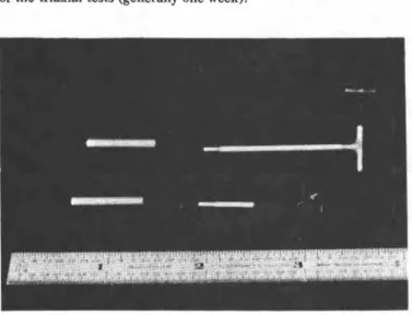
Three 24DC-DT-100 displacement transducers, having a dis- placement range of k 2.54 mm ( ? 0.10 in.), were employed for deformation measurements. A 24DC-DT-500 displacement trans- ducer with a displacement range of ? 12.7 mm ( k 0.50 in.) was used for the external measurement of axial strain for comparison. These transducers were supplied by Hewlett-Packard Co., com- plete with core assembly. Figure 1 shows the gage points and the extension rods adapted to the cores for axial and lateral deforma- tion measurements. Subsequent attachment of the extension rods to the gage points was made by means of a rapid-setting adhesive (Arena alpha No. 102).
As the experimental investigation involved measurements with delicate electronic instruments in the triaxial cell under pressure, the cell fluid had to be a nonconductor and had to be noncor- rosive to any part of the displacement transducers. The normal cell fluid (water) was not suitable. A transformer oil, Esso Univolt N-36, was found to be satisfactory.
A separate inlet to the triaxial cell was provided for the trans- former oil so that the cell pressure could be applied through the water-pressure system, as described by Bishop and Henkel [IS]. The oil and water interface was indicated by a glass reservoir installed along the pressure line.
Membrane for Soil Specimen
Latex rubber membrane, which is commonly used, tends to expand and deteriorate in oil as a result of chemical interaction. A special order was placed to manufacture silicone rubber sheets 0.381 mm (0.015 in.) in thickness from a product under the trade name Silastic 1125U (134-llK), produced by Dow Coming Co. The sheets were then made into tubular forms using a com- patible silicone sealant (room-temperature vulcanizing) as a glue and were cured for at least 24 h.
The membrane proved to be sufficiently oil-resistant an< exhibited a fairly low degree of expansion within the duration of the triaxial tests (generally one week).
FIG. 1-Gage points and extension rods for displacement transducers in axial and lateral strain measurement.
Calibration of Transducers
The displacement transducers were calibrated in air as well as in the transformer oil by means of a micrometer to an accuracy of 1.02 pm (4 x in.) It was found that the relationship between the displacement of the core and the output voltage was essentially linear, and the performance of the transducer was practically unaltered when calibrated in the transformer oil.
A calibration constant of 0.245 pm/mV (9.65 x in./mV) was obtained in both cases. It was also observed that the trans- ducers were stable under the cell pressures and that the effects of temperature variations on the output voltages were negligible under normal laboratory test conditions ( ? 2OC).
The calibration of the displacement transducer used for the purpose of comparative external deformation measurements was performed in a similar manner in air, where a calibration constant of 1.02 pm/mV (4 x in./mV) was attained. Both calibra- tions were performed with a constant 24-V d-c excitation voltage.
Support Systems for the Displacement Transducers
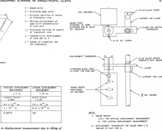
The usual procedure for the use of a displacement transducer is to provide a rigid mounting with the core aligned in the direc- tion of displacement. However, if coupled displacements in the principal directions should occur, there is a tendency for the core to tilt. Since the output signal of the transducer is highly sensitive to the position of the core, tilting of the core will induce an error, the amount of which depends on the length of the extension rod and the magnitude of the accompanying displacements in the perpendicular directions. Figure 2 shows the relative error in- volved in the axial and lateral displacement measurements as a result of tilting of the core. It may be observed that:
1. With a long extension rod for the core and relatively small lateral displacements, the effect of tilting is insignificant.
2. With a short extension rod (limited by the space available in the triaxial cell) and relatively large accompanying axial dis- placements, the error imposed on the lateral displacement mea- surement would be substantial.
3. Apart from the effects on the displacements, excessive tilting of the core and the extension rod assembly would induce undesirable moments on the gage points, thus impairing the accuracy of the measurement.
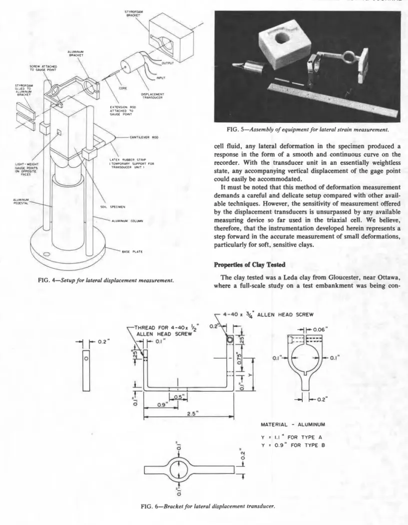
4. The bore of the displacement transducer is only slightly oversized to allow for the axial movement of the core. Excessive tilting in the core would tend to increase the frictional forces which might inhibit the instantaneous response of the transducer. It is therefore acceptable to use rigid supports (Fig. 3) for the transducers in the internal axial-deformation measurements; however, it is apparent that a rigid support system for the trans- ducers would be unsuitable for measuring the lateral deformation. A procedure was developed based on the principle of flotation by which the lateral displacement transducers were made buoyant in the cell fluid. In an essentially weightless state, the transducer units could follow the vertical displacement of the gage points while the cores were free to move laterally along the bores of the transducers, thus registering reliably the lateral displacements of the gage points with virtually no stress applied to the specimen as a consequence of the instrumentation.
The basic setup for the lateral displacement measurement (in one of the principal directions) is illustrated in Fig. 4, and the
YUEN ET AL ON MEASURING STRAINS IN ANISOTROPIC CLAYS 27
A
-
Gaged p o i n t I8 = D i s p l a c e d gage p o i n t SOIL SPECIMEN 10-24 ALLEN SCREW C = O r i g i n a l p o s i t i o n o f c e n t r e
:,j)
o f t r a n s d u c e r c o r e S U P m T FOR CLAMPX = Maximum d i s p l a c e m e n t o f
gage p o i n t p e r p e n d i c u l a r GAUGE POINT
-
t o c o r e a x i s ATTACHED TO CORE EXTENSION ROD BY OUlCK CLAMP FOR VERTICAL C1= D i s p l a c e d ~ o s i t i o n of c e n t r e TRANSDUCER of t r a n s d u c e r c o r e y = I n d u c e d a x i a l d i s p l a c e m e n t of c o r e due t o X L = L e n a t h o f e x t e n s i o n r o d 6 - 3 2 SET SCREW % c l ~ i f o r t r a n s d u c e r % tl e
i..
.a .-'t'
I DISPLACEMENT TRLNY*KER 0 10-24 ALLEN SCREWCOMPLETE WITH WASHER A x i s of D i s p l a c e m e n t
T r a n s d u c e r
STYROFOAM BLOCK SIZED
L2 = ( L - Y ) ~ + X2 TO FLOAT THE CORE UNIT
y
SUPPORT FOR CLAMP
6WGE W I W S POSITIONED ON SPECIMEN
NOTES
I ) GAUGE POINTS
A 8 C FOR VERTICAL DISPLACEMENT MEASUREMENT B - FOR LATERAL DISPLACEMENT MEASUREMENT 21 DISPLACEMENT TRANSDUCER FOR GAUGE POINT C IS FIG. 2-Relative error in displacement measurement due to tilting of SIMILAR TO THAT FOR A .
core.
FIG. 3-Genezal arrangement of supports for vertical transducer units.
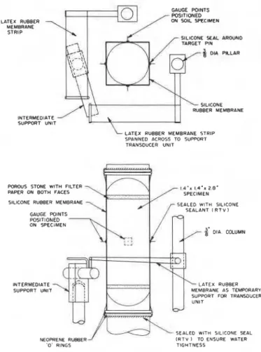
components are shown in Fig. 5. The displacement transducer port for each lateral transducer unit was in the form of a thin was mounted on an aluminum bracket (Fig. 6), which was so latex-rubber membrane stretched horizontally across two canti- \ proportioned that the center of gravity of the assembly was lever rods attached to aluminum columns from the base plate of close to the center of the transducer. The design of the aluminum the cell (Fig. 4). Since the weight of the transducer unit was con- brackets permitted deformation measurements to be made in two centrated at the transducer end, only one strip of latex was orthogonal directions, as depicted in Fig. 7. The transducer end necessary for each unit. By adjusting the position of the cantilever of the assembly was fitted into a Styrofoam@ bracket, and small rods, the axis of the transducer unit could be aligned with the Styrofoam pieces were glued to the opposite end of the bracket to position of the gage points. When the lateral displacements in provide balanced flotation. the two orthogonal directions were to be measured, an additional The Styrofoam used was a lightweight foam with a density of temporary support was provided for the adjacent transducer unit. approximately 40.19 kg/m3 (2.51 Ib/fP). It was found that 2.8 g The details of the support system are given in Fig. 8. The setup (0.1 OZ) of Styrofoam was sufficient to float the unit (transducer is shown in Fig. 9.
with aluminum bracket) which weighed approximately 45.4 g With the transducers supported temporarily (Fig. lo), the (0.1 Ib). Since there was a tendency for the foam to become extension rods of the cores were attached to the gage points with saturated with oil under the cell pressure, the Styrofoam was rapid-setting adhesive. At the same time, the positions of the "pre-pressurized" in oil under a of 138 kPa (20 psi). cores were adjusted so that their centers were close to the electrical Trial flotation was conducted by using a dummy of the same zero. A very slight disturbance was inevitable when the trans- size and weight as the actual displacement transducer unit. The ducer units started to become buoyant and as the support col- Styrofoam bracket and the end pieces were trimmed as required lapsed under the action of the oil. Nevertheless, once equilibrium so that the whole assembly was barely buoyant in a horizontal condition was reached, the output signals were stable and were position. adjusted electrically to provide a zero reading on the recorder. Until the cell was filled with oil, the units had to be mechan- Figure 11 shows the lateral transducers floating in equilibrium in ically supported. Since the measuring system was inside the cell, the triaxial cell.
access to it was very difficult; therefore, a self-collapsible tem- When the transducers were active, the effectiveness of flotation porary support was desirable. After some experimentation, it was was reflected in the output curves from the strip recorder. Pre- found that latex rubber, as mentioned earlier, deteriorated in a vious experience had shown that any friction between the cores matter of minutes when immersed in the transformer oil, which and the bores of the transducers produced discontinuous output had been adopted as cell fluid. Accordingly, the temporary sup- signals. However, when the transducers were floating freely in the
28 GEOTECHNICAL TESTING JOURNAL lLUMlNUM DISPL4CEMENT TRINSDUCER EXTENSION ROD ATTACHED TO GAUGE POlNT
FIG. 5-Assembly of equipment for lateral strain measurement.
cell fluid, any lateral deformation in the specimen produced a response in the form of a smooth and continuous curve on the recorder. With the transducer unit in an essentially weightless state, any accompanying vertical displacement of the gage point could easily be accommodated.
It must be noted that this method of deformation measurement demands a careful and delicate setup compared with other avail- able techniques. However, the sensitivity of measurement offered by the displacement transducers is unsurpassed by any available
bLUMINUM COLUMN measuring device so far used in the triaxial cell. We believe,
therefore, that the instrumentation developed herein represents a step forward in the accurate measurement of small deformations, particularly for soft, sensitive clays.
Properties of Clay Tested
FIG. 4-Setup for lateral displacement measurement. The clay tested was a Leda clay from Gloucester, near Ottawa,
where a full-scale study on a test embankment was being con-
'
i
4 - 4 0 1 3cALLEN HEAD SCREW HREAD FOR 4 - 4 0 x 1/2" 0.2'ALLEN HEAD SCREW
MATERIAL
-
ALUMINUM Y = 1.1 " FOR TYPE AY = 0 . 9 " FOR TYPE B
YUEN ET AL ON MEASURING STRAINS IN ANISOTROPIC CLAYS
29
BRACKET TYPE A
BY T H I N LATEX RUBBER MEMBRANE STRIP
( STYROFOAM BRACKETS NOT SHOWN Fig. 7-Layout of lateral displacement transducers.
ducted by the National Research Council of Canada [16]. Block samples, taken by excavating a test trench to a depth of 2.4 m (8 ft) below the ground surface, were waxed and preserved under 100% humidity. The properties of this clay at this particular location have been extensively investigated by Bozozuk and Leonards [16], Law [ l a , and Lo et al [18]. Typical properties of
LATEX RUBBER MEMBRANE STRIP GAUGE W l N T S
F-=
/
,s~P,NEkc.EN AROUND PILLAR RUBBER MEMBRANE INTERMEDIATE SUPPORT UNITLATEX RUBBER MEMBRANE STRIP SPANNED ACROSS TO SUPPORT TRANSDUCER UNlT
POROUS STONE WlTH FILTER
PAPER ON BOTH FACES
,-
1 4 " " 1.4.n SPECIMEN 2 8 "SILICONE RUBBER MEMBRANE \
r
x
SEALED WlTH SILICONEPOSITIONED ON SPECIMEN
2'
DIA. COLUMNINTERMEDIATE LATEX RUBBER
SUPPORT UNIT MBRANE AS TEMPORARY
SUPPORT FOR TRANSDUCER
1
SEALED WlTH SILICONE SEALNEOPRENE RUBBER I R T V I TO ENSURE WATER
0' RINGS TIGHTNESS
FIG. 8-Support system for lateral transducers. RTV = room tem- perature vulcanizing.
FIG. 9-Temporary supports for transducer units in lateral strain
measurement in the orthogonal directions.
the clay are liquid limit, 45%; plastic limit, 22%; and natural water content, 65%. The undrained shear strength is about 24.8 kPa (3.6 psi) with a sensitivity of 15 from field vane tests. The clay is slightly overconsolidated with a preconsolidation pressure of 55 kPa (8 psi).
Experimental Program
The objectives of the test program were (1) to obtain per- formance data for the apparatus developed and (2) to assess the anisotropic behavior for a particular clay. A summary of the types and the special features of the deformation measurements in each of the triaxial tests is given in Table 1. For purposes of comparison, the natural moisture contents and the volume changes during consolidation of the specimens are presented in the same table.
All triaxial tests were performed on square-sectioned specimens 35.6 mm (1.4 in.) square by 71.1 mm (2.8 in.) high trimmed from block samples. the use of parallel-sided specimens avoided the ambiguity of the direction of principal stresses found in a cylin- drical specimen and at the same time facilitated the use of in- strumentation for measuring lateral deformations.
In all the tests performed, the consolidation pressure was 21 kPa (3 psi) and the back pressure was 69 kPa (10 psi). All the triaxial tests were strain-controlled with strain rates of 0.08%/h [16.9 nm/s (0.00004 in./min)] and 0.5%/h [101.6 nm/s (0.00024 in./min)] for the drained and undrained tests, respectively. The outputs from the pressure transducers and displacement trans-
GEOTECHNICAL TESTING JOURNAL
FIG. 10-Transducer units supported temporarily in lateral strain measurement in the orthogonal directions.
ducers were displayed on a strip recorder, which enabled a simul- taneous and continuous monitoring of the test results.
Results of Testa
The analysis and interpretation of the test results have been discussed in detail by Lo et al [I]. In this paper, some aspects of the experimental data relating to the performance of the appa- ratus and the significance of the deformation measurements will be examined.
Homogeneity of the Samples
It may be observed from Table 1 that the specimens have natural moisture contents ranging from 65 to 69% for isotropically consolidated undrained (CIU) tests and from 68 to 70% for isotropically consolidated drained (CID) tests. These small varia- tions in the natural moisture content give an indication that the block sample used for the triaxial tests in this study was fairly homogeneous for a natural deposit. A further check on the homogeneity of the sample may be made by comparing the total volume changes in the specimens during the consolidation stages, in which all the specimens were subjected to the same hydrostatic state of stress. With the exception of the inclined s p e ~ i m e n , ~ the S ~ h e large volume of change is due to induced internal shear stress in
an anistropy body.
FIG. 11-Transducer units floating in equilibrium in lateral strain measurement within the triaxial cell.
volume changes in each of the vertical (i = 0 deg) and horizontal
(i = 90 deg) specimens are in close agreement (where i is the angle between the axis of symmetry of the soil deposit and the long axis of the test specimen).
In addition to these observations, it has also been found that the pore-pressure-axial-strain relationships of all the vertical specimens tested in the undrained condition were practically identical. Similar trends were noted for the horizontal specimens. These experimental results show that the test specimens were sufficiently homogeneous to be used for comparison purposes. On this basis, test results obtained from different triaxial tests may be combined to give additional data for assessing the per- formance of the apparatus developed.
Axial Strains
A comparison of the axial strains, measured internally [gage length = 35.6 mm (1.4 in.)] and externally outside the triaxial cell for a CIU test on a horizontal specimen (HI), is shown in Fig. 1242. It may be observed that the internal axial strain is con- sistently lower than the external axial strain. The same observa- tions have been made in a vertical specimen (Vl). Since it has been noted that the specimens were fairly homogeneous, similar patterns of axial deformation would be expected in other speci- mens tested in the undrained condition. It follows that appropriate corrections could be applied to the external strains in order to
YUEN ET AL ON MEASURING STRAINS IN ANISOTROPIC CLAYS
3
1TABLE 1-Summary of tests perjormed on a Leda clay.
Natural Volume Change
Orientation of Moisture in Consolidation
Specimen No. Type of Test Specimen, deg Content, % Stage, % Special Test Feature
c l u a CIU CIU CIU CIU CID CID CID CID
internal axial deformation measured orthogonal lateral deformations measured at
mid-height
lateral deformations measured at quarter
points in one direction
internal axial deformation measured orthogonal lateral deformations measured at
mid-height
orthogonal lateral deformations measured internal axial deformation measured orthogonal lateral deformations measured
a CIU = isotropically consolidated undrained.
CID = isotropically consolidated drained.
'i = angle between the axis of symmetry of the soil deposit and the long axis of the test specimen.
!
GAUGE LENGTH
FOR EXTERNAL WUOE Lrrnru
AXIAL STRAIN FDP I N T E R N I L
w m - 2 8 I N &XIPL STR4iN
Q
d Z 0 4 0 6 0.
EXTERNAL AXIAL STRAIN 1%) 1 0 ) C I U T E S T ON HORIZONTAL S P E C I M E N H I
- 0 . l 5 r 9
LATERAL STRAIN E,. 1%1 i b l C I U T E S T O N VERTICAL SPECIMEN V 2 a 0.06 0 0 4 002 - 0 0 2 - 0 0 4 - 0 0 6 - 0 0 8 LATERAL 5TR4IN L,, ( 9 , ) 0 LOADING D UNLOADING l c l C I D T E S T ON V E R T I C A L S P E C I M E N V 4
FIG. 12-Relationships between the principal strains in CIU and CZD
tests.
obtain the true internal axial strains in the CIU tests. In the CID tests, however, the difference between the external and internal axial strains is very small; no such corrections are therefore necessary.
Lateral Strains
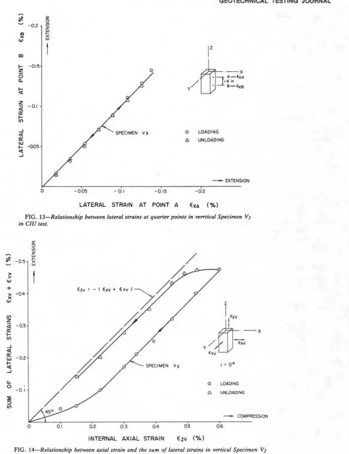
The uniformity of lateral strain within the middle half of the specimen was investigated by measuring the lateral deformations
a t quarter points of a vertical specimen ( V 3 ) across two opposite
faces. The results given in Fig. 13 show that the lateral strains
independently measured a t the quarter points are almost identical for both loading and unloading, indicating that the lateral strain distribution within the middle half of the specimen is essentially uniform.
The lateral strains in orthogonal directions in the x-y plane are
given in Fig. 1% for a CIU test on a vertical specimen (V2). It
can be seen that the two lateral strains ex and g were almost
identical for both loading and unloading. This phenomenon suggests that the deformation behavior of the soil is isotropic in
the x-y plane. Figure 12c shows the results of a CID test on a
vertical specimen ( V 4 ) , and similar observations may be made.
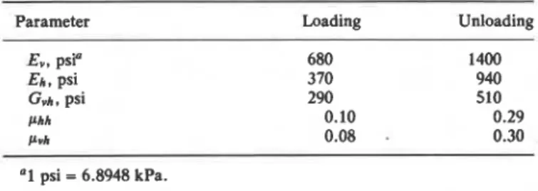
Sum of Principal Strains
By combining the axial strains in Specimen V1 and the lateral
strains in two orthogonal directions in Specimen V2, the sum of
the principal strains (ex,
+
g ,+
E,,) a t any stage of loading andunloading may be studied. The results are plotted in Fig. 14 in
such a form that the dotted 45-deg line which passes through the origin represents the condition for an incompressible material
(ex,
+
eyv+
eZv = 0 ) . It may be noted that there seems to be a lag in the response of the lateral strains a t the initial stages of loading and unloading. The behavior is reflected in the initial nonlinearities in the curves plotted. However, if incremental strain components are considered along the linearized portions of the curves, the incremental strain behavior is very close to thatof an incompressible material (AE,,
+
AE,,+
A€,, = 0 ) .One possible explanation for this initial behavior is that even though the transducer assembly is essentially weightless in the cell fluid, it is likely that a small amount of friction may occur between the core and the bore of the displacement transducer. A small amount of deformation would be absorbed before the movement in the core is initiated. The effect of this initial dis- crepancy is nevertheless very small since the incremental stress- strain theory was employed in the analysis of the test results [ I ] .
GEOTECHNICAL TESTING JOURNAL
0 LOhDlNG
O UNLOADING
LATERAL STRAIN AT POINT A EXA ( % I
FIG. 13-Relationship between lateral strains at quarter points in verrtical Specimen V3
in CIU test.
INTERNAL AXIAL STRAIN Ezv ( % I
FIG. 14-Relationship between axial strain and the sum of lateral strains in vertical Specimen V2
in CIU test.
On the basis of the performance data described above, we have evaluate the cross-anisotropic elastic parameters of this clay concluded that the apparatus developed yielded adequate accu- deposit using the incremental stress-strain theory described by racy and stability in measuring the deformations of a soft sensi- Lo et al [ I ] . A set of the elastic anisotropic parameters determined tive clay. With all the principal strains accurately measured in from consolidated-drained tests is shown in Table 2. It is clear both the drained and undrained triaxial tests, it is possible to that the clay tested was significantly anisotropic.
YUEN ET AL ON MEASURING STRAINS IN ANISOTROPIC CLAYS
33
TABLE 2-Anisotropic elastic parameters for a Leda clay determinedfrom CID tests.
Parameter Loading Unloading
Ev, psi" Eh, psi Gvh, psi Phh Pvh "1 psi = 6.8948 kPa. Concluding Remarks
While the strength behavior of anisotropic clays has been investigated in terms of both total and effective stresses, the study of anisotropic deformation behavior has been rarely per- formed, probably because of the inadequacy of conventional test apparatus for accurate measurements of small lateral deforma- tion.
This paper describes an apparatus and an experimental ar- rangement that appear to fulfill this purpose. The system employs light gage points and displacement transducers floated in a cell fluid so that internal strains may be measured directly on the specimen with the least amount of disturbance. Using specimens trimmed from a block sample of a soft sensitive clay, performance data have been obtained to indicate that the apparatus developed possesses adequate precision and stability for the study of defor- mation behavior of clays.
Acknowledgment
The research performed was supported by the National Re- search Council of Canada under Grant A7745.
References
[ I ] Lo, K. Y., Leonards, G. A., and Yuen, C. M. K., "Interpretation and Significance of Anisotropic Deformation Behavior of Soft
Clays," i n h u n t s B j e m m Memorial Volume (Addendum), N. Janbu, F. Jdrsted, and B. Kjaernsli, Eds., Norwegian Geotechnical Insti- tute, Oslo, Norway, in press.
[2] Conlon, R. I., Tanner, R. G., and Caldwell, K. L., "The Geo- Technical Design of the Townline Road-Rail Tunnel," Canadian
Geotechnical Journal, Vol. 8, No. 2., 1971, pp. 299-314.
[3] Lo, K. Y. and Morin, J. P., "Strength Anisotropy and Time Effects
of Two Sensitive Clays," Canadian Geotechnical Journal. Vol. 9, No. 3, 1972, pp. 261-277.
[4] Freeman, W. S. and Sutherland, H. B., "Slope Stability Analysis in Anisotropic Winnipeg Clays," Canadian Geotechnical Journal, Vol. 11, NO. 1, 1974, pp. 59-71.
[ S ] Love, A. E. H., Mathematical Theory of Elasticity, Cambridge
University Press, Cambridge, 1972.
[6] Hearmon, R . F. S., An Introduction to Applied Anisotropic Elus-
ticity, Oxford University Press, London, 1961.
[n
Lekhnitskii, S. G., Theory of Elasticity of an Anisotropic Body,translated by P. Fern, Holden-Day, San Francisco, 1963.
181 Pickering, D. J., "Anisotropic Elastic Parameters for Soil," Geo-
technique, Vol. 20, No. 3, 1970, pp. 271-276.
[9] Gibson, R. E., "The Analytical Method in Soil Mechanics," Geo- technique, Vol. 24, No. 2, 1974, pp. 115-140.
[ l o ] Barden, L., "Stresses and Displacements in a Cross Anisotropic Soil," Geotechnique, Vol. 13, No. 3, 1963, pp. 198-209.
[Ill Lee, I. K.. Ed., Soil Mechanics Selected Topics, American Elsevier,
New York, 1968.
(121 Roscoe, K. H., Arthur, J. R. F., and James, R. G., "The Deter- mination of Strains in Soils by an X-Ray Method." Civil Engi-
neering and Public Works Review. Vol. 58, 1963, p. 873.
[I31 Holubec, I. and Finn, P. J.. "A Lateral Deformation Transducer for Triaxial Testing," Canadian Geotechnical Journal, Vol. 6, August. 1969. pp. 353-356.
[14] El-Ruwayih, A. A., "Design Manufacture and Performance of a Lateral Strain Device," Geotechnique. Vol. 26, No. 1, 1976, pp.
215-216.
1151 Bishop, A. W., and Henkel, D. J., The Measurement of Soil R o p -
erties in the Triarial Test, 2nd ed., Edward Arnold & CO.,
London, 1962.
1161 Bozozuk, M. and Leonards, G. A., "The Gloucester Test Fill," Proceedings of the ASCE Specialty Conference on Performance of
Earth and Earth-Supported Structures, Purdue University, West
Lafayette, Ind., 1972, pp. 299-317.
[rq
Law, K. T., "Analysis of Embankments on Sensitive Clays," Ph.D.thesis, University of Western Ontario, London, Ontario, 1975. 1181 Lo, K. Y . , Bozozuk, M., and Law, K. T., "Settlement Analysis of
the Gloucester Test Fill," Canadian Geotechnical Journal. Vol. 13, No. 4, 1976, pp. 339-354.