Publisher’s version / Version de l'éditeur:
Canadian Geotechnical Journal, 19, 4, pp. 401-412, 1982-11
READ THESE TERMS AND CONDITIONS CAREFULLY BEFORE USING THIS WEBSITE. https://nrc-publications.canada.ca/eng/copyright
Vous avez des questions? Nous pouvons vous aider. Pour communiquer directement avec un auteur, consultez la première page de la revue dans laquelle son article a été publié afin de trouver ses coordonnées. Si vous n’arrivez pas à les repérer, communiquez avec nous à [email protected].
Questions? Contact the NRC Publications Archive team at
[email protected]. If you wish to email the authors directly, please see the first page of the publication for their contact information.
NRC Publications Archive
Archives des publications du CNRC
This publication could be one of several versions: author’s original, accepted manuscript or the publisher’s version. / La version de cette publication peut être l’une des suivantes : la version prépublication de l’auteur, la version acceptée du manuscrit ou la version de l’éditeur.
Access and use of this website and the material on it are subject to the Terms and Conditions set forth at
A One-dimensional analytical model for snow creep pressures of rigid
structures
McClung, D. M.
https://publications-cnrc.canada.ca/fra/droits
L’accès à ce site Web et l’utilisation de son contenu sont assujettis aux conditions présentées dans le site
LISEZ CES CONDITIONS ATTENTIVEMENT AVANT D’UTILISER CE SITE WEB.
NRC Publications Record / Notice d'Archives des publications de CNRC:
https://nrc-publications.canada.ca/eng/view/object/?id=c19d30e9-1be1-450b-95ac-d0507637f6ba https://publications-cnrc.canada.ca/fra/voir/objet/?id=c19d30e9-1be1-450b-95ac-d0507637f6baSar TH1
N21a
' National Research Conseil national
1g49
Council Canada de recherches Canada C .BLDG
iA ONE-DIMENSIONAL ANALYTICAL MODEL FOR
SNOW CREEP PRESSURES ON RIGID STRUCTURES
ANALYZED
Reprinted from
Canadian Geotechnical Journal Vol. 19, 1982
pp. 401-412
DBR Paper No. 1049
Division of Building Research
-.
7 .*BLDG.
RES.
L l B R A R Y
83-
01-
?
l
BIBLIOTHEQUE
Re&. B3rim.
C , ' r s T t . -Price $1.25 OTTAWA NRCC 20585 ,.This publication is being distributed by the Division of Building Research of the National Research Council of Canada. It should not
be reproduced in whole or in part without permission of the original publisher. The Division would be glad to be of assistance in obtaining such permission.
Publications of the Division may be obtained by mailing the appropriate remittance (a Bank, Express, or Post Office Money Order, or a cheque, made payable to the Receiver General of Canada, credit NRC) to the National Research Council of Canada, Ottawa. KIA 0R6. Stamps are not acceptable.
A list of all publications of the Division is available and may be
obtained from the Publications Section. Division of Building Research, National Research Council of'canada, Ottawa. ~ l i
A
one-dimensional analytical model for snow creep pressures on rigid structures
DAVID M. MCCLUNGBritish Columbia Regional Station, Division of Building Research, National Research Council of Canada, 3904 W . 4th Ave., Vancouver, B . C . , Canada V6R IP5
Received September 9, 1981 Accepted April 2 1, 1982
An analytical model for quasi-static creep forces parallel to the slope at the centre of a long rigid structure on a snow-covered slope is derived and checked by the finite element method. The formulation accounts for interruption of snow creep (internal deformation) and glide (slip of the entire snowpack over the ground). The average pressure and length of the zone of influence of the structure upslope are predicted fairly accurately for the range of parameters of interest in comparison with finite element results assuming linear creep and glide constitutive laws. The model is also compared with the equations provided by Haefeli as used in the Swiss Guidelines for Avalanche Defense.
Un modble analytique, pour le calcul des forces quasi-statiques de fluage agissant parallklement ?Ila pente au centre d'une structure longue et rigide placCe sur une pente couverte de neige, est Ctabli et vCrifiC par la mCthode des ClCments finis. La formulation tient compte de I'intermption du fluage de la neige (deformation interne) et du glissement (diplacement du couvert de neige sur le sol). La pression moyenne et la longueur de la zone d'influence de la structure vers I'amont de la pente sont prCdites avec une prCcision convenable dans le domaine des parambtres CtudiCs, lorsqu'on compare les rksultats il ceux
d'un calcul en ClCments finis utilisant des lois de comportement IinCaires pour le fluage et le glissement. Le modble est Cgalement compare aux Cquations proposCes par Haefeli et utilisCes dans les recommandations suisses pour la protection contre les avalanches (Swiss Guidelines for Avalanche Defense).
[Traduit par la revue]
Can. Geotech. J., 19,401-412 (1982)
Introduction Bucher (1948) attempted a two-dimensional analyti- The design of structures to be placed on mountain cal model. Bucher's solution for the interruption of slopes with deep snow covers often requires knowledge creep behind a structure contains inconsistencies, how- of the forces caused by interruption of creep within the ever (Salm 1977). In addition, his formulation does not snowpack (internal deformation) and glide (slip of the include glide, which is the most important component of entire snowpack over the ground). The simplest problem pressure in many cases (Salm 1977).
of this nature is that of plane strain in two dimensions, Haefeli (1948; see also Bader et al. 1939) made the which is the calculation of pressures exerted at the centre first attempt to formulate an essentially one-dimensional of a rigid structure placed perpendicular to the ground model to simulate plane strain snow pressure calcula- and transverse to the fall line. Near the centre, far from tions, and the problem which he defined has become one the end of the structure, the problem becomes two- of the classic problems in snow mechanics. Haefeli's dimensional and edge effects can be ignored. McClung formulation can be shown to give reasonable values for (1974) gave the first solution to this problem using the snow pressure in some cases (McClung 1974; Salm finite element method. Brown and Evans (1975), Lang- 1977). However, his equations are not accurate in don (1975), and McClung (1976a), extended this general for all slope angles and snow parameters even procedure. though they are still used today in the Swiss Guidelines The finite element method is a very powerful tool for for Avalanche Defense (Salm 1977). Furthermore, such problems. For example, nonlinearity in creep and Haefeli's formulation cannot be derived using con- glide constitutive properties as well as complex geome- tinuum pechanics even though many of his physical tries are easily included. Many consultants, however, assumptions appear to be reasonable.
will not have easy access to programs with features, The present paper gives an analytical model for snow such as line spring elements, needed to formulate glide creep pressures due to interruption of creep and glide boundary conditions. In addition, numerical solutions processes at the centre of a long rigid structure on a do little to clarify the physical interdependence of the snow-covered slope. One immediate use of the formula- creep and glide parameters. Furthermore, the nature of tion is for easy calculation of pressures at the centre of the nonlinearity in snow constitutive properties is at avalanche defense structures where edge effects can be present not defined well enough to justify precise models ignored. Another use is that the plane strain model featuring nonlinear formulations. Thus, many of the defines the minimum base line pressures on such advantages of numerical procedures are lost. structures. Structures of more complex geometry will
OOO8-3674/82/040401-12$01 .OO/O
402 CAN. GEOTECH. I. VOL. 19, 1982 feel higher effective pressures that those given by the
solution of the plane strain problem because of edge effects. The plane strain model points the way to solution of these three-dimensional cases.
The present model is obtained by reducing the plane strain problem to one-dimensional deformation by averaging quantities through the depth of the snowpack. This procedure results in simple formulae for pressures in terms of two dimensionless snow~ack deformation parameters: the viscous analog of Poisson's ratio (a creep parameter), and a parameter for glide termed a relative stagnation depth. Both of these are easily measured for regions free of longitudinal gradients of stresses and material properties (called hereafter a neutral zone). The model. as well as finite element checks, is cornpared throughout with Haefeli's model, since his formulation is used at present as the standard by most consultants wishing to estimate creep pressures on structures.
Characteristics of snow creep for deep alpine snowpacks
In reality, internal deformation of alpine snow might be idealized using elastic-visco-plastic modelling. The problem dealt with in this paper is concerned with the slow deformation of deep snow covers of well settled snow, however, and any elastic deformation may be safely ignored compared with viscous and plastic effects. Furthermore, complications such as rapid densi- fication of new snow layers are ignored here. Field measurements (Larsen et al., in preparation) show, in fact, that once a deep, well settled snow cover several metres thick is in place, new fallen, low density snow usually contributes negligibly to measured creep pres- sures except by the addition of higher body forces:
When deformations are such that elastic strains may be neglected, most elastic-visco-plastic solids behave in effect as non-Newtonian fluids (Zienkiewicz 1977). While we acknowledge that non-Newtonian modelling, or even more complex visco-plastic constitutive rela- tions featuring a dependence on loading history, may provide more accurate models, for the present paper we ignore such complexity. We assume instead a linear compressible viscous constitutive equation that is equiv- alent to that for a Newtonian viscous fluid, neglecting the static fluid pressure term (Salm 1967).
Our reasons for this choice are the followine. (1) The u \ , simplicity of linear modelling yields snow pressure equations that predict the average pressure on the structure in a simple analytical form usable by any consultant. (2) solution of the linear problem permits comparison with the model given by Haefeli (1948) which implies a similar assumption and which has been the standard used by consultants for many years. (3) The nonlinear constitutive equations proposed and used to
date in this problem by McClung (1974, 1976a, 1980), Brown and Evans (1975), and Langdon (1975) are weakly nonlinear; they predict small differences in the average pressure and only about a 15% increase in maximum pressure compared with a linear creep law. Since in the present paper we emphasize average rather than maximum values, there is no advantage to the added complexity of these formulations. (4) The linear problem is worthy of study because its solution allows easy comparison with field measurements and departure from linearity may be easily illustrated.
As we show later, for the linear problem the formula- tion turns out to be dependent only upon the ratio of shear to bulk viscosity, which may be expressed in terms of a viscous analog of Poisson's ratio, v. The value of v may be allowed to increase with time as densification proceeds so that by exploring variations in it we may extend our model to the simplest time-dependent model- ling.
In general, the downslope deformation of a snow cover on a slope can be resolved into components parallel and perpendicular to the slope. The amount of slope parallel deformation, which we term shear defor- mation, relative to the slope perpendicular or vertical deformation depends upon the slope angle and the viscous analog of Poisson's ratio for linear, neutral zone deformation.
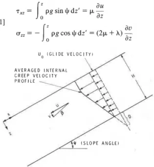
Consider an isotropic snowpack deforming linearly in a neutral zone. The shear and vertical stress may be defined as (Fig. l),
I:
a
u T,, = pg sin I) dz' = p - az [ll au o n = - ~ z p g c ~ s g d z ' = ( 2 p + h ) - o dz U o ( G L I D E V E L O C I T Y ) A V E R A G E D I N T E R N A L C R E E P V E L O C I T Y tFIG. 1. Definition of coordinate system, stagnation depth, D, creep angle,
P,
and creep velocity components (u, v); Uo is the glide velocity and+
is the slope angle.McCLUNG 403
where u and u are creep velocity components, p and A are the shear viscosity and viscous analog of Lame's constant respectively, and p is density. Taking the ratio of these expressions (for z # 0 and z # H) gives:
[2] tan J, = - -
: ;
-( 2 + l h / p )
where A/p = 2v/(l - 2v).
Using the definition of the neutral zone deformation rate coefficient (Perla 1972) CD =
-
[du/dz)/(du/az)], [2] becomes:As long as one is far from the boundaries, i.e., the free surface at the top of the snowpack or the restraint condition at the snow-earth interface, CD for the present linear problem admits a simple, geometric interpretation defined originally by Haefeli and emphasized by Perla (Fig. 1). For this case we can write CD = tan
P
whereP
is the creep angle, defined as the ratio of creep velocity components, tanp
= - u/u.Rewriting [3] gives:
[4] tanp = - l ( l - - 2 v ) cot
*
2 1 - vThis equation predicts that the component of shear deformation is greater than the component of vertical deformation for $
>
26.6" and v>
0. For slope angles near 45", which is a typical avalanche starting zone angle, the deformation would be overwhelmingly in shear for v>
0. This consideration is the basis for the assumption of simple shear deformation in the present one-dimensional model for slope angles near 45". Slope angles near 30" show a significant vertical deformation component that must be accounted for to yield accurate snow pressure formulations.Characteristics of glide in mountain snowpacks Glide is the slip of the entire snowpack over the ground. It accounts for the most important components of snow pressure in many instances (Salm 1977).
For quasi-static problems a description of glide is required in terms of constitutive equations that relate tangential drag on the snowpack to slip velocity. These equations may, in general, be very complex since they depend upon the interface roughness, water content, and snow rheology.
Salm (1977) and McClung (19766, 1980, 1981)
'
suggested two mechanisms for glide. McClung (1980, 198 1) provided approximate constitutive equations re-
i
lating tangential drag to slip velocity for the case where a perfect slip condition, guaranteed by the presence of a continuous water film, exists at the snow-earth inter- face.
Field measurements show that glide does not occur unless the interface temperature reaches 0°C and water is present. For interface temperatures lower than 0°C the snowpack is either frozen to the ground or friction is too high to allow glide without water as a lubricant. For instances in which a perfect slip condition (continuous water film) is not maintained at the glide interface, friction may have to be introduced; this can greatly complicate the glide constitutive relation. However, for the present paper we assume a perfect slip condition in order to retain the simplicity of a linear glide law. There are at present no data to justify the added complexity of this kind of friction in connection with snow pressure problems although it is very likely that this may be an important feature of future, more complex models.
The suggested mechanisms for glide are: (i) creep over roughness asperities at the interface; and (ii) sliding at points where the snowpack becomes separated from the interface asperities by a thin water film allowing the pack to move as a rigid body.
For mechanism (i), we retain our assumption of a linear, viscous creep model. In that case, in the neutral zone, the glide constitutive equation relating tangential drag, 7 , to the neutral zone glide velocity, Uo, for the creep mechanism can be written (McClung 1981):
where D' is a function of the geometry of the interface boundary conditions and of v.
The neutral zone constitutive equation for sliding concurrent with separation is (McClung 1980, 1981) [6] 7 = p, UO x function (geometry of boundary)
where p, is the viscosity of water at 0°C.
Since [5] and [6] are linear relations between 7 and
Uo, we can express them in a single equation in cases where both mechanisms operate:
where now D has theoretical limits between 0 (no glide) and w (no drag).
The parameter D has a geometrical interpretation in the neutral zone and the best way to estimate it is by measuring both creep and glide components on a slope in a neutral zone and then determining D by geometrical construction (Fig. 1). Salm (1977) estimated, from measurements in Switzerland by a different method, that D has approximate limits 0 5 D 5 3H; these estimates
404 CAN. GEOTECH. J. VOL. 19, 1982
are used in the remainder of this paper. When glide takes place only by creep (viscous flow) over asperities, D reduces to D f as in [5], and it is evident that D
<
H (McClung 1981).The previously mentioned considerations for glide apply to the neutral zone. We can generalize these considerations to express a constitutive equation for glide behind a structure as:
l . 4 ~ )
[8] T(X) =
-
= f (x, z)u(x) D(x, z)If we assume a constant interface roughness and water content at the glide interface in the zone of influence of the structure, [8] becomes:
U
with D taken as constant all along the interface.
boundary conditions as:
u = 0 at x = 0 (deformation halted at structure)
-
-e =
emax
at x = 0 (maximum value of at structure) [I31u = Uo for x + w (neutral zone value of
glide velocity out of zone of influence of structure)
2
= 0 for x + 03 (neutraLzone value of ii = -Po outside influence of structure) To introduce the glide constitutive equation we multi- ply [ l l ] by and integrate to get:"
- dii du[14]
1
O H i f - d x ' = / x [ ~ g - ~ ( x f ) ] ( - a ) dxf o dx'Distribution of glide velocity behind a structure Use of [12] in [I41 gives: Consider the geometry of Fig. 2, with quantities
-
eaveraged through the depth of the snowpack. Further, ,151
1;
E ~ H Z ~
dzf = -1:
[I. - T(U')] ~ U Iassume initially that the snowpack is very stiff so that emar
most of the deformation takes place along the glide Along the glide interface we wish to satisfy the glide
,
interface. Consider only viscous motion in the x constitutive equation given by [9]. Substitution of [9] in direction initially and constant interface roughness and [15] yields:water content along the glide interface in the zone of
influence of the structure. -(emax2 HEf
-
Z2) = T ~ U-
iku2Depth-averaged quantities are defined as: 2
I
I1101
t i = -
J
% d zH 0 - du
[16] b 2 =
(&)
= emu2-
In this manner the equation of equilibrium for slow HE' HE'
motion becomes: This is a nonlinear differential equation. Since u = Uo dii
-
andZ
= 0 for x -, w, we can expressZm,
as:[ l l ] H-= pgH sin$-T(X)
=
7 , - ~ ( x )d X - ( T ~
uo)
'I2 -(
T:')
'I2[17]
emax
=-
--
For this problem we assume a depth-averaged, linear, HE' kHEf compressible, viscous constitutive equationequivalent where = C / ~ is termed a glide stiffness. to a Newtonian viscous fluid with neglect of static fluid substituting [171 into [16] gives:
pressure:
1121
a
=E':-P~
with E f = 2p,/(1 - v).
- For the strain rate is defined approximately as: rejecting the (+) solution, so that we have a well
e
-
-du/dx and behaved solution for x + 03, and with u = 0 at x = 0,H we get:
&
=( Y )
1
pp(cos$)zdz H 1 - v 0 - v-
H [19] u=' [ I - e x p ( - G x ) ] -- pg(c0s *)?
k 1 - vUsing the creep constitutive equation [12] we can For the geometry of Fig. 2, we can express the calculate the pressure on the structure for this simple
McCLUNG
R l G l D O B S T A C L
model:
FIG. 2. Geometry for the one-dimensional model.
The first term in [21] will be termed the dynamic pressure, whereas the second term represents a quantity analogous to hydrostatic pressure due to the restraint of lateral expansion under vertical stress, here called static pressure. This formulation has assumed deformation only along the glide interface so that the pressure on the structure will be underestimated since interruption of creep processes within the snowpack has not been taken into account.
One-dimensional model of snow pressure without deformation perpendicular to the slope
In order to account for the interruption of longitudinal creep processes within the snowpack by the structure we retain the equation of equilibrium [ l l ] and develop a constitutive relation T(U) for creep and glide processes. This will ensure that creep is interrupted in the same manner as glide. This is similar to an assumption by Haefeli.
To include internal deformation we write the consti- tutive equation T,, = p (duldz), which is applicable through the depth of the snowpack assuming simple shear deformation only. The averaged creep constitutive equation will then be of the form:
where L1 is an unknown length scale in the problem. For simple shear deformation we can write a simple relationship from the definition of strain:
where UA is the creep velocity at the top of the snow-
pack. If we assume, for example, a linear (triangular) velocity profile then, in terms of the average creep velocity in the snowpack, we can write down a relation- ship
where kl is a creep stiffness and the length scale L1 from [22] is
1
H.In order to include both creep and glide in our model we couple the creep and glide stiffnesses as for viscous dashpots in series. The previously derived solution for glide only could be viewed in this manner, with glide stiffness coupled to a creep stiffness kl -+ m. For stiff-
nesses in series the equivalent effective stiffness is:
Thus, an appropriate constitutive equation for creep and glide is:
Now, repeating the derivation for [19], with kt re- placing k, we get:
and
[28] $0) =
-jgH
sin+
[&zm]
The second term represents the average static pres- sure and the first term gives a representative average dynamic pressure due to interruption of creep and glide processes.
It is of interest to note that creep and glide stiffness will not couple as parallel elements in the foregoing
CAN. GEOTECH. J. VOL. 19, 1982
,-FREE S U R F A C E
N E U T R A L Z O N E V E L O C I T Y C O M P O N E N T S
FIG. 3. Schematic of finite eleme
problem because that would imply zero dynamic pres-
sure when D = 0, which is not physically reasonable.
In order to calculate the snow pressure for engineering applications, one wishes to know the most negative principal stress. For the one-dimensional model, since the shear stress is zero at the structure, it is clear that the most negative principal stress, GI, is given by [28] as GI
= a(0).
Comparison with numerical calculations and Haefeli's equations for $ = 45"
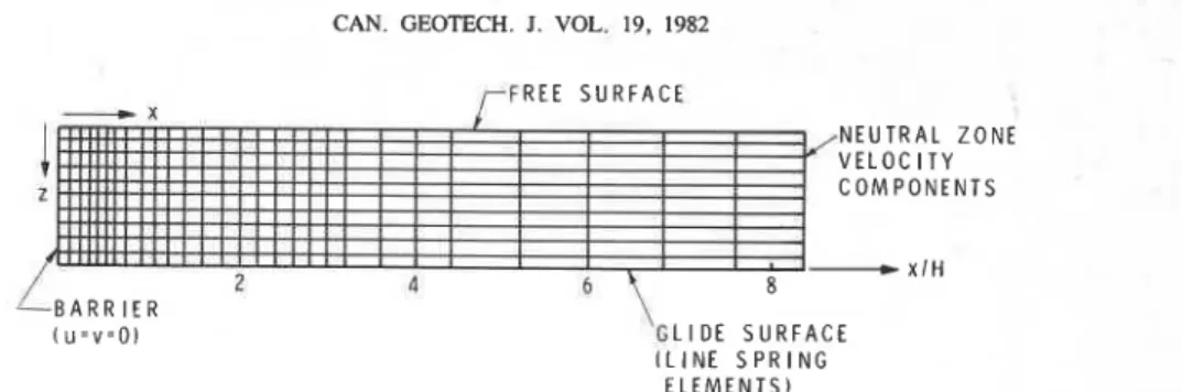
For the present linear problem it is of interest to compare the one-dimensional model with numerical calculations by the finite element method. McClung (1974, 1976a) outlined the method for these calcula- tions. Figure 3 shows a typical finite element mesh with the assumed boundary conditions. Special line spring elements are taken at the glide interface in order to use a
relation of the form T(X) = (~,/D)u(x) with D taken, for
example, to have a range in accord with Salm's (1977) estimates. A linear compressible viscous constitutive equation is assumed for the snowpack deformation for comparison with our model which features the same assumption.
Haefeli's (1948) expression for the average pressure can be written (Salm 1977) in the present notation as:
-
-'gH [(I - 2 tan ~ ~cos3 ~
+
0 )[29] ~ ~ ( 0 ) =
-
2 c0s2
*
1
(
2)
"
'
(
);3"'1
+-
-
sin 214.1 1+
-
3 tan
From the definition of the creep angle in [4],
and [29] becomes:
[30] GH(0) = - p g H sin
+
[:
-(
-
-
;:;v)112 co:
*
( L I N E S P R I N G E L E M E N T S )
:nt mesh and boundary conditions.
Comparison of [30] with [28] indicates that the differences lie in the quantities in square brackets in the first terms of these models, the static pressures being equivalent. With the boundary conditions of Fig. 3, the finite element calculations give only the dynamic pres- sure (McClung 1974, 1 9 7 6 ~ ) .
We first consider IJJ = 45" where we expect that
deformation effects perpendicular to the slope will be small and the simple shear approximation is expected to be accurate. Therefore, we compare the quantities in brackets in the dynamic term with the most negative principal stress calculated for two-dimensional finite element calculations. We express the first term (the
dynamic pressure only) as a primed quantity
6'
so thatlGI'/~gl
gives the bracketed portion of the dynamicpressure in [28] and [30]. Note that (ZI1/~,( is a function
of D / H and v only for a given
+.
Figure 4 shows a typical comparison of
l&'/~,1
withnumerical calculations and Haefeli's model as a function
of height on the structure for $ = 45"; v = 0.25; D / H =
0.5. In this case Haefeli's equations lead to overestima- tion of the average pressure-when compared with finite element calculations or the one-dimensional model.
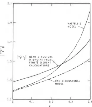
Figure 5 shows lGI1/~,l as a function of v in
comparison with Haefeli's model for
+
= 45"; D / H =0.2. Also shown is the maximum value, luI'/~gl (uI1
without a bar means maximum value of dynamic pressure) from the finite element calculations near the centre of the structure. For example, the value taken
from a comparison such as Fig. 4 would be ( u I 1 / ~ , ( =
1.73. Figure 5 shows that the one-dimensional model
displays the same dependence on v as the finite element
method. Haefeli's model, on the other hand, shows a much stronger dependence on v than the one-dimensional model or finite element results. In fact, Haefeli's model
diverges for v = 0.5. Figure 6 depicts a similar
comparison as a function of D / H for v = 0.25 and
JI
=45".
his
shows that Haefeli's model displays stronger dependence on D / H than the one-dimensional model or the finite element method.The results of Figs. 5 and 6 indicate that we can match
the finite element results for maximum pressure near the
McCLUNG 407 I I I I I I I I
-
t I I - I I I - I - I I I I M O D E L I 1 I IFIG. 4. Typical comparison of graphs of ratio of dynamic
component of pressure to T~ VS. height on the structure (-.-
denotes one-dimensional model; --- denotes Haefeli's model; 0-0 denotes finite element calculations; arrow denotes value of l u l ' / ~ ~ l for the calculation;
IJJ
= 45"; v = 0.25; D/H= 0.5).
FIG. 5. Comparison of graphs of ratio of dynamic compo-
nent of pressure to T~ VS. v for JI = 45O, D/H = 0.2 (-.-
denotes one-dimensional model; --- denotes Haefeli's model;
-
denotes lul'/~gl near structure midpoint from finite element calculations). HAEFELI'S MOOEL'+,--d
1.C I I I I P 0 2 0.5 1 0 2 0 3.0 OIHFIG. 6. Comparison of graphs of ratio of dynamic compo-
nent of pressure to T~ VS. D/H for
IJJ
= 45'; v = 0.25 (-.-denotes one-dimensional model; --- denotes Haefeli's model;
-
denotesl ~ ~ ' / ~ ~ 1
near structure midpoint from finite element calculations).v = 0.25 yields avalue for luIf/~,l of 1.28. This suggests that a combined creep and glide stiffness of F / ( D
+
0.6H) would give the maximum pressure, u l , near the centre of the structure, as:
,311 u1 = - j g H sin
I
/-
+
[,
1 - vThe maximum pressure is introduced here not as a major feature of the model, but to illustrate the easy compari- son with finite element calculations, and also for easy comparison with nonlinear models in future work.
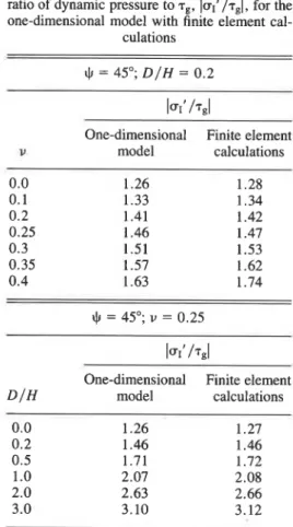
Table 1 shows calculated values for the expression in square brackets in [31], IuIf / ~ , l , with finite element values for
+
= 45". It is emphasized here that, although the comparison in Table 1 appears to indicate highly accurate results for the one-dimensional model, the model in general will not display such accuracy. We have matched the values for the case IJ = 45" to illustratethat the shapes of the curves in Figs. 5 and 6 are the same.
Figures 5 and 6 illustrate that Haefeli's model displays a different dependence on v and D / H from that of finite element calculations or the one-dimensional model, including divergence when v + 0.5.
Haefeli's formulation contains the concept of a back-pressure zone or length of the zone of influence of the structure upslope. For the one-dimensional model with an exponential dependence upon distance, the
408 CAN. GEOTECH. J. VOL. 19, 1982
TABLE 1. Comparison of maximum value of the ratio of dynamic pressure to T,, luI1/rgl, for the one-dimensional model with finite element cal-
culations
-
lur' / ~ g l
One-dimensional Finite element
u model calculations
l ~ 1 ' l T g l
One-dimensional Finite element
D/H model calculations
back-pressure zone is theoretically infinite. We could, however, define a relevant distance by recognizing that the exponential velocity distribution will return to 99% of the neutral zone value in the distance:
The expression of Haefeli that is analogous to [32] is (Salm 1977):
2H
,331
xb=-
[(=)(Icos
*
1-
2vFinite element calculations show that [32] is an accurate estimate for
+
= 45". For the calculations given by McClung ( 1 9 7 6 ~ ) for D / H = 0.06 and 0.32, H = 3.54 m, v = 0.3, and+
= 45", we get, respectively, X'= 22 and 27 m, in agreement with the reported values of 21 and 28 m. For most applications, however, it is difficult to define the back-pressure zone accurately in finite element schemes because larger elements are normally taken as the distance from the structure increases.
Figure 7 shows a typical comparison of glide velocity in the back-pressure zone from the finite element calculations with velocity from the one-dimensional model for
JI
= 45", D / H = 0.32, and v = 0.3. Calculation from [32] gives X' / H = 7.7, whereas [33] yields Xb/H = 5.2. Haefeli's equations consistently underestimate the back-pressure zone lengths when compared with the one-dimensional model or finite element calculations.Extension to low slope angles: approximate inclusion of deformation perpendicular to the slope in the
one-dimensional model
The one-dimensional model assumes simple shear deformation and does not include deformation effects perpendicular to the slope. For slope angles less than 45", there can be higher pressures than predicted by the one-dimensional model due to interruption of vertical deformation. Finite element calculations indicate that both the dynamic pressure and the back- pressure zone are larger than the estimates of the one-dimensional model for slope angles less than 45".
Equation [4] predicts that shear deformation equals vertical deformation for
+
= 26.6", v = 0 in the neutral zone and that the ratio of vertical deformation to shear deformation increases as i[(1 - 2v)/(l-
v)] cot+.
Within the context of our one-dimensional model, we wish to write a constitutive equation of the form of [26] to include vertical deformation, since 7, = p(du/dz+
aulax). In addition, it seems reasonable to couple vertical deformation to glide deformation and shear deformation in the same manner that glide is coupled to shear deformation. This suggests that [25] may be replaced by:
Similarly to [22], the problem is to define the missing
s
0 1 0 2 0 3 0 4 0 5.0 6.0
XIH IRELATIVE DISTANCE UPSLOPE FROM THE STRUCTURE1
FIG. 7. Comparison of glide velocity behind a structure from two-dimensional finite element calculations (0-0) with velocity from the one-dimensional model (-.-) ( U o is neutral zone glide velocity; X / H is relative distance upslope fromthestructure; DIH = 0 . 3 2 ; ~ = 0.3;$ = 45").
McCLUNG 409 length scale for vertical deformation, L2. With the verticaldeformationeffects woulddisappearasv+ 0.5, previous considerations a reasonable estimate for L2 as expected from the definition of the creep angle. From
should be: [35], [34] becomes:
Such an estimate gives L1 = L2 = + H for
+
= 26.6", vL
-
' \ I - v l J= 0 as we may expect from neutral zone conditions. In
addition, for
+
= 45", L2 is zero and hence independent Repeating the derivation of [19] and [21], with K' re- of v, as finite element calculations show. Furthermore, placing k, gives:- - v - H
[37] u1 = - pgH sin
+
'/(A)[;+;
[ l + ( c o t + - 1) (ll:?)]] --
pg cos+
for+
5 45"; [28] is the estimate for+
r 45".For the maximum stress near the centre of the structure we can similarly write:
- 1
-
2v v - H[38] UI =
-
p g ~ sin+
J ( ~ ) [ ; + 0 . 6 [ i + ( c o t + - 1 j-
-I-vPgiCOs*for (I 5 45", and [31] remains the estimate for
+
r 45".Similarly, for the back-pressure zone, [32] is the estimate for
+
2 45". For+
5 45", we can write an estimate of X' from previous considerations:D 1
,391 X' = 5H
[(L)
[-
+
- [1+
(cot+
- 1)1 - v H 2
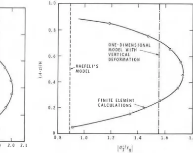
Finite element calculations show that these formulae are accurate, at least down to slope angles near 25". Figure 8 shows a comparison for
+
= 30°, D / H =4,
and v = 0.25. Calculations of X' / H from [39] gives X' / H= 9.1, whereas the finite element estimate is X' / H = 9.2. Haefeli's estimate gives Xb/H = 5.4. Calculation of la1' / T ~ [ gives 1.92 whereas finite element results give
1.98 for a 3% error.
Figure 9 depicts a similar comparison for D / H = 0 (no glide) and v = 0.25,
+
= 24". In this case Haefeli's model gives only about 50% of the maximum pressure. For ~ U ~ ' / T ~ [ we get 1.70 whereas finite element calcula-tions give 1.73 for a 2% error. For the back-pressure zone we get X' /H = 7.7 whereas finite element calculations give about 8. Haefeli's estimate gives
X b / H = 2.7. This comparison, without glide for a slope of low angle, shows the biggest disagreement between Haefeli's model and the one-dimensional model. The reason for better agreement in the previous examples is
that Haefeli's stronger dependence on glide overcom- pensated so that the somewhat better agreement was fortuitous. It should be noted that Haefeli's equations contain a dependence upon 1 /(cos +) that has an effect on slope angle opposite to that predicted by finite element calculations or the one-dimensional model, thereby enhancing the discrepancy for slopes of low angle.
Comparison with force estimates from Swiss guidelines for avalanche defense
The Swiss guidelines for avalanche defense (Switzer- land 1968) provide estimates of the total force parallel to the slope per unit width at the middle section of an avalanche defense structure. These calculations are assumed to be valid away from the structure ends so that edge effects can be ignored.
For the one-dimensional model, a representative total force S parallel to the slope per unit width is given by:
[40] S =
- p g ~ 2
sin+
[Jm]
-
& ~ g $cos 4410 CAN. GEOTECH. J. VOL. 19. 1982
for
+
I 45".The equivalent expression for Haefeli's model as used in the guidelines can be extracted from the paper by Salm (1977):
2 1 - v v
-
H~1421 S, =
- p g ~ 2
sin $[-
(-)
'I2(&) (1+
g)
'I2] --
pg-i-
cos $3 1 - 2 v 1 - v
Again, comparison of these expressions shows that the differences lie in the brackets in the dynamic terms and the previous comparisons apply. It is clear that the equations in the guidelines will overestimate or under- estimate the pressures in comparison with the one- dimensional model or finite element calculations, de- pending on the chosen parameters.
The Swiss guidelines separate the dynamic term into a product of expressions called creep and glide factors. A glide factor is defined from the dynamic term by assuming D = 0 (no glide), and then the remaining portion is divided by the resultant. If we follow this prescription for the one-dimensional model we get (1
+
2D/H)lI2 as the glide factor for+
r 45'. It is clear, however, that this is not very useful terminology for the one-dimensional model because such an expression1 . 0 - I I I I,
,
I I I I 0 . 8-
I 0 . 6-
I I 0 . 4-
I I 0.2-
I H A E F E L I ' S I M O D E L<
I I I I 1 1 I 0 I I 1 1 1 -1.1 I . ? 1 . 3 1 . 4 1.5 1 . 6 1 . J 1.B 1.9 2.0 2 . 1results from coupling creep and glide into the problem. Salm (1977) used this concept to determine the limits on D / H that are used in this paper. The glide factor for Haefeli's equations is (1
+
~ D / H ) " ~ . The highest glide factor from the Swiss guidelines (Switzerland 1968) is 3.2, which yields 0 5 D / H 5 3 for Haefeli's model.Since the validity of the definition of such a glide factor is open to question it would be more advisable to rely on actual measurements of D from neutral zones according to the geometrical definition of D (Fig. 1).
Summary
A one-dimensional model of the plane strain problem for snow creep pressures on structures has been devel- oped and checked by the finite element method. The I
model predicts the average pressure parallel to the slope on a rigid structure and the back-pressure zone length
1.0 I I I I I
I [
I I I I MOOLL W I T H 0 . 6 - 1 V E R T I C A L I D E F O R M A T I O NCHAEFEL
1 8 s I M O D E Li
I I I 0 . I I 1 I I 0. B 1 . 0 1. 2 1.4 1. 6 1. Bl'iiTgI
FIG. 9. Comparison of graphs of ratio of dynamic compo-
FIG. 8. Comparison of variation of ratio of dynamic com- nent of press& to T, vs. height on the structure for the case
ponent of pressure to 7, with height on the structure (-.- D / H = 0 (no glide) for $ = 24", v = 0.25. This case shows the
denotes one-dimensional model with vertical deformation; greatest discrepancy between the one-dimensional model and
--- denotes Haefeli's model; 0-0 denotes finite element Haefeli's model (-.- denotes one-dimensional model with
calculations; D / H = 0.5; v = 0.25; $ = 30" where settlement vertical deformation; --- denotes Haefeli's model; 0-0
fairly accurately when compared with the numerical calculations for the ranges of the two important parame- ters in the model: 0 5 v 5 0.5,O 5 D / H 5 3 for slope
angles at least as low as 25".
The two parameters in the model, v and D I H , are easily measured (McClung 1974) in neutral zones where they both have geometrical definitions. The parameter v
is derived from the geometrical interpretation of a creep angle and this interpretation is strictly valid only near the midsection of a thick, relatively homogeneous, isotropic snowpack. The cfeep angle is, for example, undefined at the snow-earth interface and it loses meaning at the snow-atmosphere interface.
In contrast, Haefeli's (1948) model and, hence, the Swiss guidelines for avalanche defense display different behaviour than either numerical calculations or the one-dimensional model. The main differences are as follows.
(1) Haefeli's model shows stronger dependence on v
and is in fact divergent as v + 0.5.
(2) Haefeli's moYdel displays stronger dependence on D I H .
(3) The pressures given by Haefeli's model for slope angles near 25" are much lower than either finite element calculations or the one-dimensional model, apparently because of neglect of vertical deformation effects.
McCLUNG 41 1
The extension of the one-dimensional model to low slope angles near 25" should be taken as an approxima- tion. For slopes of low angle and for low v values the problem becomes more two-dimensional in character as the slope angle decreases. Finite element calculations show, however, that accounting for vertical deformation is an important consideration for such problems and the creep pressure can be significantly higher than predicted by models that do not take vertical deformation into account. The ratio lEI'/~gl increases rapidly as
+
decreases below 45" whereas Haefeli's model actually predicts a dependence of l/(cos +), which has the opposite effect.The present model assumes linear creep and glide constitutive laws. In reality, we strongly emphasize that nonlinearity may be present in both of these descrip- tions. More sophisticated models will almost certainly be required to match experimental data accurately. Previous attempts with nonlinear modelling have shown that nonlinearity is particularly likely to affect the maximum value of pressure, which is why we empha- size only the average values predicted by the simplistic modelling in the present paper.
Another feature that is likely to appear in field data is the time-dependence of pressure increase by visco- plastic compaction. For the present paper, time depend- ence may be introduced crudely by increasing v as densification proceeds under the same body forces.
However, changes in v for well settled alpine snow would be expected to be small and the implied Poisson effects for the linear problem would leave very little lati- tude for pressure increases with time. It seems doubtful that field data could logically be matched by this effect.
While we do not expect that our simple model can match the complex nonlinear and time-dependent fea- tures that we expect to be evident in field data, it is not obvious that these shortcomings detract greatly from the model as a useful tool for estimating the average pressure on a structure. In addition, study of the linear problem may enable us to pinpoint the features that deserve our attention in future modelling.
Acknowledgements
Much of this work was accomplished while the author was a Postdoctoral Fellow with Environment Canada and their support is gratefully acknowledged. Thanks are also due to P. A. Schaerer, National Research Council of Canada, G. K. C. Clarke, University of British Columbia, and C. B. Brown, University of Washington, for reading the manuscript prior to submis- sion. This paper is a contribution from the Division of Building Research of the National Research Council of Canada and is published with the approval of the Director of the Division.
BADER, H., HAEFELI, R., BUCHER, E., NEHERER, J., ECKEL,
O., Thams, C., and NIGGLI, P. 1939. Der Schnee und seine Metamorphose, Beitrage zur Geologie der Schweiz. Geo- technische Serie, Hydrologie, Lief. 3. (German, English translation, U.S. Snow, Ice and Permafrost Establishment, Trans. 14, 1954.)
BROWN, C. B., and EVANS, R. J. 1975. Effect of glide and creep on rigid obstacles. Association Internationale des Sciences Hydrologiques, Commission des Neiges et Glaces, Symposium Mecanique de la neige, Actes du colloque de Grindelwald, 1974, (IAHS-AISH Publication No. 114),
pp. 407-414.
BUCHER, E. 1948. Beitrag zu den theoretischen Grundlagen des Lawinenverbaus. Beitrage zur Geologie der Schweiz. Geotechnische Serie, Hydrologie, Bern, Lief. 6 .
HAEFELI, R. 1948. Schnee, Lawinen, Firn und Gletscher. In
Ingenieur-Geologie. 2 Bd. Edited by L. Bendel, Springer- Verlag, Vienna, pp. 663-735.
LANGDON, J. A. 1975. Approximate solutions for the intermp- tion of creep and glide by avalanche defenses. M.Sc. thesis, Department of Civil Engineering, University of Washing- ton, Seattle, WA.
LARSEN, J. O., MCCLUNG, D. M., and HANSEN, S. B. In preparation. The temporal and spatial distribution of snow- pressure on structures.
MCCLUNG, D. M . 1974. Avalanche defense mechanics. Ph.D. thesis, Geophysics Program, University of Washing- ton, Seattle, WA.
1976a. Snow pressure on rigid obstacles. Journal of Glaciology, 17, pp. 277-285.
412 CAN. GEOTECH. .I.VOL. 19, 1982 1976b. Laws of friction in snow mechanics. Fjell-
sprengningsteknikk, Bergmekanikk, Geoteknikk, 1975. Norsk Jord og Fjellteknisk Forbund. Tillnyttet NIF, Tapir Press, Norway, pp. 26.1-26.6.
1980. Creep and glide processes in mountain snow- packs. National Hydrology Research Institute, Paper No. 6, Environment Canada, Ottawa, Ont., 66 p.
1981. A physical theory of snow gliding. Canadian Geotechnical Journal, 18, pp. 86-94.
PERLA, R. I. 1972. Generalization of Haefeli's creep-angle analysis. Journal of Glaciology, 11, pp. 447-450. SALM, B. 1967. An attempt to clarify triaxial creep mechanics
of snow. Proceedings, International Conference on Low , Temperature Science, 1966, Sapporo, Vol. I, Part 2, pp.
857-874.
i
1977. Snow forces. Journal of Glaciology, 19, pp. 67-100.
SWITZERLAND. 1968. Lawinenverbau im Anbruchgebiet. Richtlinien des Eidgenossischen Oberforstinspektorates fiir des Stutzverbau. Mitteilungen des Eidgenossischen Insti- tutes fur Schnee- und Lawinenforschung, Nr. 29, Davos, Switzerland.
ZIENKIEWICZ, 0. Z. 1977. The finite element method. 3rd ed. McGraw-Hill Book Company Ltd., London, England.
![Figure 8 shows a comparison for + = 30°, D / H = 4, and v = 0.25. Calculations of X' / H from [39] gives X' / H](https://thumb-eu.123doks.com/thumbv2/123doknet/14323619.497447/12.781.33.755.45.582/figure-shows-comparison-d-h-calculations-x-gives.webp)