HAL Id: inria-00070214
https://hal.inria.fr/inria-00070214
Submitted on 19 May 2006HAL is a multi-disciplinary open access
archive for the deposit and dissemination of sci-entific research documents, whether they are pub-lished or not. The documents may come from teaching and research institutions in France or abroad, or from public or private research centers.
L’archive ouverte pluridisciplinaire HAL, est destinée au dépôt et à la diffusion de documents scientifiques de niveau recherche, publiés ou non, émanant des établissements d’enseignement et de recherche français ou étrangers, des laboratoires publics ou privés.
FPGA Configuration of Intensive Multimedia Processing
Tasks Modeled in UML
Sébastien Le Beux, Jean-Luc Dekeyser, Philippe Marquet
To cite this version:
Sébastien Le Beux, Jean-Luc Dekeyser, Philippe Marquet. FPGA Configuration of Intensive Multi-media Processing Tasks Modeled in UML. [Research Report] RR-5810, INRIA. 2006, pp.13. �inria-00070214�
ISSN 0249-6399
ISRN INRIA/RR--5810--FR+ENG
a p p o r t
d e r e c h e r c h e
Thème COMINSTITUT NATIONAL DE RECHERCHE EN INFORMATIQUE ET EN AUTOMATIQUE
FPGA Configuration of Intensive Multimedia
Processing Tasks Modeled in UML
Sébastien Le Beux, Philippe Marquet, Jean-Luc Dekeyser LIFL, USTL
Cité Scientifique
59 655 Villeneuve d’Ascq Cedex
Email: Sebastien.Le-Beux@lifl.fr,Philippe.Marquet@lifl.fr, Jean-Luc.Dekeyser@lifl.fr
N° 5810
January 20, 2006Unité de recherche INRIA Futurs Parc Club Orsay Université, ZAC des Vignes, 4, rue Jacques Monod, 91893 ORSAY Cedex (France)
Téléphone : +33 1 72 92 59 00 — Télécopie : +33 1 72 92 59 ??
FPGA Configuration of Intensive Multimedia Processing Tasks Modeled
in UML
Sébastien Le Beux, Philippe Marquet, Jean-Luc Dekeyser LIFL, USTL
Cité Scientifique
59 655 Villeneuve d’Ascq Cedex
Email: Sebastien.Le-Beux@lifl.fr,Philippe.Marquet@lifl.fr, Jean-Luc.Dekeyser@lifl.fr
Thème COM — Systèmes communicants Projet DaRT
Rapport de recherche n° 5810 — January 20, 2006 — 13 pages
Abstract: Recent research have demonstrate interests in a codesign framework that allows
descrip-tion refinement at different abstracdescrip-tion level. We have proposed such a framework that allows SoC resources allocation for regular and repetitive tasks found in intensive multimedia applications.
Nevertheless, the framework does not directly target reconfigurable architectures, the difficult job of placing and routing an application on a FPGA being postponed to a dedicated tool. In order to limit the number of synthesis on this external tool, we propose an algorithm that, from a high level description of an intensive multimedia application, estimates the resource usages on a given FPGA architecture. This algorithm makes use of a simple mathematical formalism issued from case study implementations.
Implémentation sur FPGA d’applications de traitement de signal intensif
modélisées en UML
Résumé : De récentes recherches ont démontré l’intérêt d’utiliser une chaîne de conception conjointe
permettant le raffinement d’une description, et ceci à différents niveaux d’abstration. Nous avons proposé une plateforme répondant à ces attentes. Elle assure l’allocation de ressources contenues dans un SOC, permettant ainsi l’implémentation de tâches répétitives, isolées dans des applications de type multimédia.
Néanmoins, cette plateforme ne cible pas directement l’architecture reconfigurable. Le difficile travail de placement et routage sur FPGA est réalisé ultérieurement par un outil dédié. Afin de limiter le nombre de synthèses à réaliser par l’outil dédié, nous proposons un algorithme permettant, à partir d’une description de haut niveau de l’application, une estimation des ressources exploitées pour une architecture cible donnée. Cet algorithme utilise des formulations mathématiques simples, elles-même obtenues à partir d’implémentations réelles.
FPGA Configuration of Intensive Multimedia Processing Tasks Modeled in UML 3
Introduction
We introduce in this paper a Gaspard (Graphical Array Specification for PARallel and Distributed computing) extension. Gaspard is a co-design platform, whom proposition came from a triple state-ment of facts:
• On the application side, complexity of applications such as MPEG-2 encoder [7], requires a high level of modeling.
• On hardware side, heterogeneous and multiprocessor Systems on Chip (SoC) are the rising trend [9]. A high level model of architecture description and abstraction face up to these com-plexity of SoC design.
• On the last side, codesign platform seems to be appropriate to model the different levels of details needed by the codesign of embedded systems [8].
The software community has successfully faced the complexity of their design. Tools such as UML (Unified Modeling Language) are commonly used nowadays. Based on this success, exten-sions of such modeling tools for the description of hardware and hardware/software integration are proposed.
Gaspard framework is more specifically oriented toward the codesign of parallel software and hardware. Gaspard specially identifies the parallelism included in regular construction such as ap-plication loops or repetitive constructions of hardware elements. This kind of parallelism covers both the targeted intensive multimedia applications and the targeted hardware such as FPGA or multi-processors. Gaspard proposes a UML modeling of each step of the codesign. The new version of Gaspard targets the exploitation of reconfigurable architectures. One aspect that argues for the us-age of reconfigurable architectures into SoC is that their integration allows to extend or modify the system functionalities without a new foundry.
Nevertheless, Gaspard will not be extended to the process mapping of an application on a FPGA. We choose to exploit already available tools. Gaspard will provide to these tools an application tuned to the targeted component. Information provided by external tools permits to introduce design space exploration in Gaspard framework and allows a full simulation of SOC containing reconfigurable parts.
The paper is organized as follow. We introduce Gaspard framework and the compact way of repetition expression in first section. Section 2 describes the language used to target reconfigurable architecture. We present a way to introduce repetitions at the application level in section 3. Section 4 details relevant characteristics of targeted reconfigurable architecture. Section 5 analyses results of the implementation. We conclude and give perspective to this work in the last section.
1 UML Modeling of Intensive Multimedia Processing Tasks
UML becomes a standard in many fields. In [3], Coyle et al. described a model driven architectural (MDA) approach to hardware-software codesign. From a UML description of state machine, HDL description are generated.
In our case, UML permits a clearly description of structural aspect of application and architecture. Thanks to several additions in the basic languages, it is possible to increase the modeling power of those structural aspects.
1.1 Using UML to Model Applications in Gaspard
Our first UML extensions presented in [4] have been experimented in the context of the Gaspard prototype framework [?, 10]. Gaspard is an MDA, Model Driven Architecture, oriented environment
4 Sébastien Le Beux, Philippe Marquet, Jean-Luc Dekeyser
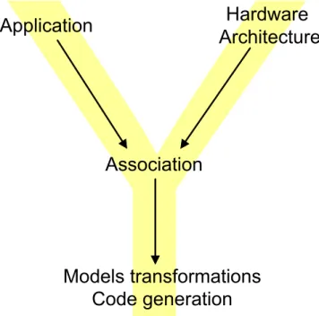
Figure 1: “Y” approach in Gaspard framework
for computation intensive tasks in embedded systems. It follows a “Y” approach (Figure 1) and, from high levels models, it enables the automatic model to model transformations and code generations, for various abstraction levels.
At the top level of the “Y”, software, hardware architecture and allocation abstract syntax are described by three different metamodels:
• application: characterizes relation between tasks;
• architecture: describes architecture at different abstraction level;
• allocation: describes mapping and scheduling of application on architecture.
Application, architecture and allocation metamodels share common modeling constructs, such as a component oriented approach and a mechanism for compact modeling introduced in [4], based on ArrayOL.
1.2 ArrayOL: express repetitive tasks
From the observations done in previous works an extension inspired by the Array Oriented Lan-guage [5, 6] that delete ambiguity problems and increase expression power of UML 2 structural modeling mechanisms has been proposed [4]. The proposed extensions enable to specify all the data dependencies that exist during application runtime. The basic idea is to identify the relations between all the potential link ends concerned by each potential link. These extensions are used for the modeling of complex topologies, and concern basically multiplicities, connectors and dependencies, in the context of composite structures.
Basically, using ArrayOL parameters, connections are describe using three main parameters: • origin: This attribute give the origin of the pattern.
• paving: Thepaving attribute is a set of vectors that enable to identify the origin of each pattern
inside of the array corresponding to a relationship end. The number of patterns contained inside of the array is determined by thepavingLimit attribute.
FPGA Configuration of Intensive Multimedia Processing Tasks Modeled in UML 5 • fitting: From each of the identified origins, the points belonging to the patterns are identified
with thefitting vectors.
That repetition mechanism allows to model applications containing several elementary tasks (from one to infinite, infinite being used to model temporal repetition) with only one elementary task contained in a repetitive structure. Connections between the repetitive structure and the ele-mentary task are detailed by a connector enriched by the ArrayOL parameters (origin, paving, fitting)
with UML tagged values. This particular connector is calledRepetitiveConnector.
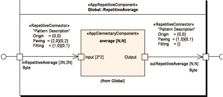
1.3 Example: An Average Filter
In order to illustrate our approach, we will follow the several steps of simple application develop-ment that process a picture. The objective is to average pixels contained in a picture encoded in gray scale (8 bits for each pixel). To produce one average pixel, four input pixels are required.
The applicationAverageComputationis realized as a repetitive structured that receives, as an
example, from its environment 16×16 signals representing the pixels composing the image. It can send to its environment 8×8 signals representing the pixels of the computed image. The order in which pixels are produced is determined by the order in which signals are received. In opposition to a usual sequential loop, the specification ofAverageComputationdoes not induce any artificial
ex-ecution order for the production of pixels. Thus, a parallel exex-ecution of theAverageComputation
application is possible. FPGA, which permit implementation of such as parallel application, is adapted to the target application.
Figure 2: Repetitive application example
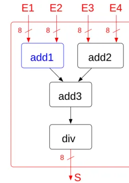
2 BLIF: A Way to Implement Application on FPGA
In UML description of application, elementary tasks can be described in any language. The objective is a FPGA configuration. Thus, code might be on RTL level. The language format chosen to describe an application is BLIF (Berckeley Logical Interchange Format) [2].
BLIF is commonly used by university tool. It is recognized as useful and efficient to work on structural aspect of application.
6 Sébastien Le Beux, Philippe Marquet, Jean-Luc Dekeyser
.model average
.inputs [List of global inputs] .outputs [List of global outputs] .clocks
.subckt add1 [List of interconnections] .subckt add2 [List of interconnections] .subckt add3 [List of interconnections] .subckt div [List of interconnections]
.model add1
.inputs [List of local inputs] .outputs [List of local outputs] .clocks
.names e5_1 e5_2 e6_1 e6_2 t2_1
1-1- 1 11-1 1 -111 1 ... .end ... .end
add2
8 8 8 8 8S
E1
E2
E3
E4
add3
add1
div
Figure 3: A partial BLIF code and its structural description
2.1 The BLIF Format
BLIF describes a logic-level hierarchical circuit in textual form. Several elementary components in-cluded in FPGA can be instantiate, such as registers, latch, Look Up Table. . .
A hierarchical mechanism permits to get a useful view of an application. We show in Figure 3 an application model in BLIF format. This application is the elementary task describe in subsection 1.3.
2.2 Exploitation of BLIF Files
Several tools permits to implement reconfigurable architecture with application described in BLIF. Two example of those tool are:
• T-VPack and VPR are tools develop by University of Toronto. Input of T-VPack is BLIF file. Output is a T-VPack netlist. This netlist can be placed and routed on FPGA architecture with VPR tool [1].
• Madeo, from University of Brest, permits a fine description of reconfigurable architecture [11]. Application, described in BLIF, can be implemented on modeled reconfigurable architecture. Several examples of implementation, like on Virtex 2 from Xilinx have validate approach of Madeo tool.
Implement application described in BLIF in those tool permits to get, among other things, per-centage of FPGA used by an application and the configuration (bitstream) to be load in FPGA.
3 Introduction of Repetition in a BLIF File
As shown in subsection 1.1, UML Gaspard profile UML permits to express dependencies between parts of this application. This repetition has to be integrated into BLIF application description.
FPGA Configuration of Intensive Multimedia Processing Tasks Modeled in UML 7
3.1 Interpretation of Repetitive Parameters
Mechanism of repetition is used to generate full application, which is partially composed of ele-mentary task instances. Let us consider the case of the simple example described in subsection 1.3, modeling with UML on Figure 2, and which source code is given in Figure 3.
3.2 Addition of Informations in Elementary Tasks
A BLIF file can be seen as a library of components. Each component (except those of lowest level), calls component of lower level.
In the case of example from subsection 1.3 a two dimension matrix is instantiated. All elementary task instances are the same, only mapping is particular to each instance.
Until now, to generate a BLIF file, only information on application have been used. Those in-formation are not sufficient to efficiently estimate placement of application on architecture. Several information on target architecture have to be given. Those characteristics permits to evaluate before synthesis if architecture can support application.
4 Improvement of the Hardware Area
During architecture implementation, it is simple to detect why a reconfigurable architecture can not support application (power computation limitation for example). But in Gaspard framework, most decisions has to be taken as soon as possible, even during architecture allocation of application.
We introduce some of this useful characteristics for a better implementation in Subsection 4.1, and treats an example in Subsection 4.2.
4.1 Architecture Characterization
FPGA Characteristics are necessary to take early decision in process development. In Gaspard UML profile, component technical characteristics are known.
Relevant technical information concerning FPGA are: • maximum frequency supported;
• maximum user Input/Output (IO) pins;
• power computation (includes number of based elements (LE for Xilinx, Logic Cell for Al-tera. . . ), DSP blocks);
• memory storage capacity; • configuration characteristics.
As the work is in progress, some elements may be added or removed.
4.2 IO Modification
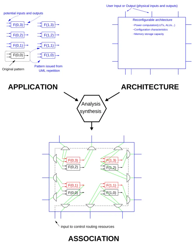
While FPGA IO pins disable implementation of all pattern, it is possible to add specific system on IO. This file modification will permit an increase of the repetition pattern number implementable on reconfigurable architecture.
Those system on IO are latchs on inputs and multiplexor on outputs. This system, according to control flow, permits to connect several “potential” IO to one “physical” IO. Those modifications are inserted automatically, during the association step shown in Figure 1.
The cost of those routing resource insertions shall be evaluated in order to choose the best com-promise. Implementation example shown in subsection 5 analyses those compromises.
8 Sébastien Le Beux, Philippe Marquet, Jean-Luc Dekeyser
4.3 Application on the Example
For example from subsection 1.3, using free parts of architecture to implement other replications of pattern is allowed. Once dedicated pins are fully used, insertion of routing elements permits an increase of tasks implementation, as shown in Figure 4.
F(0,0) F(1,0)
F(0,3) F(1,3)
F(0,2) F(1,2)
F(1,1) F(0,1)
Pattern issued from UML repetition Original pattern
potential inputs and outputs
Reconfigurable architecture
−Power computation(LUTs, ALUs...) −Configuration characteristics −Memory storage capacity
User Input or Output (physical inputs and outputs)
F(1,2) F(0,2) F(0,3) F(1,3) F(1,1) F(1,0) F(0,0) F(0,1)
input to control routing resources
ARCHITECTURE
APPLICATION
ASSOCIATION
Analysis synthesis
Figure 4: A solution to place all the pattern on reconfigurable architecture
In this section, we have seen how it was possible to introduce modification in file to implement application on architecture in an efficient way.
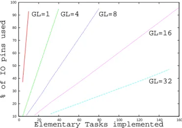
FPGA Configuration of Intensive Multimedia Processing Tasks Modeled in UML 9 10 20 30 40 50 60 70 80 90 100 0 20 40 60 80 100 120 140 160 % of IO pins used
Elementary Tasks implemented
GL=1 GL=4 GL=8
GL=16
GL=32
Figure 5: IO exploitation accordingly to the number of elementary tasks to implement and the Group-ing Level GL
5 Implementation
5.1 Extension to VHDL
All the work presented in this paper is not dedicated to BLIF format. VHDL or Verilog are two languages which could benefit of this automatic generation of routing structure. Impact of routing resource insertions (as described in subsection 4) on commercial reconfigurable architecture using VHDL has been evaluated. The target software is Altera Quartus 2, and the target architecture is a Stratix, including 10570 Logic Element and 427 IO pins dedicated to user.
The repetitive task implemented is the example shown in subsection 1.3. Each elementary task can be implemented on 27 Logic Elements.
5.2 Result Analyses
The Figures 5 and 6 have been obtain by several implementation of the application. Two parameters have been modified to produce those curves: the number of tasks to implement and grouping level GLused.
We express the number of IO used accordingly to the number of elementary tasks to implement in Figure 5. Each curve is specific to the grouping level GL used: 1, 4, 8, 16 and 32. While GL = 1, the slope is important. This demonstrate that each new implementation of elementary task required a lot of IO. Thus, IO number is the limiting factor in that case. While routing elements are introduced (GL 6= 1), constraint due to IO number is pushed back, allowing an increase of tasks allocation. GL should be increased until full computation resources of FPGA are used. In our example, for GE = 16 and for a number of tasks allocated equal to 160, 96% of IO are used. For GE = 32, a maximum of 150 tasks could be allocated while only 48% of IO are used. This means that the limiting factor has become the computation resources of FPGA.
Figure 6 permits to show that maximum power computation is used for GL ≥ 16. Moreover, while power computation used is still the same for GL ≥ 16, the maximum number of task to im-plement is quite the same. Some difference could appears, due to the imim-plementation of routing resources control, which increase according to the GL chosen (= sup(ln GL)). Neglecting this param-eter, a simple equation permits to evaluate a percentage of power computation needed by applica-tion: CP application. This equation depends on:
• NBte: number of elementary tasks implemented;
10 Sébastien Le Beux, Philippe Marquet, Jean-Luc Dekeyser
1 10 100
1 10 100
% of Logic Elements used
Grouping Level used [4:10]
[4:40] [8:80]
[16:160] [32:150]
Figure 6: Resources exploitation accordingly to the number of elementary tasks implemented (in the form of [min:max]) and the Grouping Level GL used
• P te: computation power required by one task;
• NBio: number of potential inputs and outputs of one task;
• P io: computation power required by each one of potential inputs and outputs routing re-sources;
• P te, io: computation power required by an elementary task and its routing resources; • P fpga: global computation power of FPGA;
• P allocated: % of P fpga allocated to one application; • P global: % of P fpga allocated to all application.
The equation that estimates the computation power required by the implementation of several elementary tasks can be expressed by the following formula:
P application= N Bte
P f pga× P allocated× P te, io (1)
Expression that characterizes P te, io (which expresses power computation required by an ele-mentary task and its routing resources) is given by:
P te, io=
(
P te if GL= 1
P te+PN Bio
i=1 P io(i) else
(2) Furthermore, the formula 1 can be easily adapted to the implementation of different kind of ele-mentary tasks, following this example:
P global=
N Bappication
X
i=1
P application(i) (3)
where NBappication represents the different applications to implement.
FPGA Configuration of Intensive Multimedia Processing Tasks Modeled in UML 11
NBte=1; GL=1;
while Computation power limit not reached and IO limit not reached
NBte++;
if Computation power limit reached return (NBte,1);
else
while Computation power limit not reached
NBte++;
while IO limit reached
GL++;
return (NBte,GL);
Figure 7: Number of TE (NBte) and grouping level (GL) computation
5.3 Allocation Computation
The following algorithm estimates the maximum number of elementary tasks implementable on FPGA.
The main lines of the algorithm are shown in Figure 7, other functions have to be implemented: • A function permits to test if using routing resources is useful or not;
• P allocated, percentage of FPGA resources dedicated to the application, is taken into account. Resources allocated to the several application can be di-symmetric, depending on application nature.
• In Figure 7, only the number of logic cell used is taken into account. We assume that application can instantiate DSP blocks. In the case that a percentage of DSP blocks used by each elementary task is higher than percentage of logic cell required, the number of DSP blocks is a limiting factor. However, while all DSP blocks are used, the concerned parts of application are export on logic cell. This report has been introduced in the complete algorithm.
In the study case, using GE higher than 16 is possible but not advised. Indeed, GE = 16 means that one IO pins supply 16 virtual pins. To perform a good efficiency, routing elements frequency should be about 16 times higher than Elementary Tasks frequency. In that case, where computation time of tested elementary task is short, we introduce routing elements such as big slow down tasks frequency. Thus, using routing resources can reduce power consumption needed by full application. Research are performed to estimate impact of such as insertion in full application and to insert this aspect in algorithm.
6 Conclusion
A high level modeling of complex applications is the trend. A high abstraction level allows to isolate the difficulties and facilitates the reuse of application blocks. The Gaspard platform extends this high level modeling to the codesign of embedded systems targeting multimedia applications. The application, the hardware and the association are specified in UML.
Gaspard specially targets intensive data processing applications. Among them, real-time multi-media applications present some regular parallel parts that are particularly well suited to a high level
12 Sébastien Le Beux, Philippe Marquet, Jean-Luc Dekeyser
and compact description. The new Gaspard version also aims at the usage of FPGA components as a natural target of parallel applications. FPGA also allows a rapid prototyping and are used in the design of heterogeneous SoC as they guarantee a great degree of flexibility.
Place and route application on fine grain FPGA being a tedious task, Gaspard exports this imple-mentation phase to dedicated tools provides by the FPGA manufacturers. This phase being poten-tially long, a pre-synthesis allows to a priori identify the right associations.
Our proposition is to build a structural description of the application from a high level specifica-tion. Moreover, the application behavior may be tuned thanks to a pipeline parameterizaspecifica-tion.
We have conducted several tests to validate the potential implementations. These implemen-tations aims at a maximal utilization of the FPGA resources. We have been able to formalize this resource usage with a basic mathematical model. Then, this model has been used to produce an algorithm that determines the number of tasks a given FPGA may host while supplying I/O connec-tions to these tasks.
The codesign tool Gaspard has then be augmented with a basic take into account of FPGA tar-gets. Following works consist in improvement of the proposed algorithm to take into account other parameters that may influence a system codesign, a power consumption or operating frequency.
References
[1] V. Betz, J. Rose, and A. Marquardt. Architecture and CAD for Deep-Submicron FPGAs. Kluwer
Academic Press, 1999.
[2] Berkeley logic interchange format (BLIF). Technical report, University of California, Berkeley, February 2005.
[3] Frank P. Coyle and Mitchell A. Thornton. From UML to HDL: a model driven architectural ap-proach to hardware-software co-design.Information Systems: New Generations Conference (ISNG),
pages 88–93, April 2005.
[4] Arnaud Cuccuru, Jean-Luc Dekeyser, Philippe Marquet, and Pierre Boulet. Towards UML 2 extensions for compact modeling of regular complex topologies. In MoDELS/UML 2005, ACM/IEEE 8th International Conference on Model Driven Engineering Languages and Systems,
Mon-tego Bay, Jamaica, October 2005.
[5] Alain Demeure, Anne Lafage, Emmanuel Boutillon, Didier Rozzonelli, Jean-Claude Dufourd, and Jean-Louis Marro. Array-OL : Proposition d’un formalisme tableau pour le traitement de signal multi-dimensionnel. InGretsi, Juan-Les-Pins, France, September 1995.
[6] Philippe Dumont and Pierre Boulet. Another multidimensional synchronous dataflow: Sim-ulating Array-OL in ptolemy II. Research Report RR-5516, INRIA, March 2005. http:
//www.inria.fr/rrrt/rr-5516.html.
[7] Iwasaki I., Naganuma J., Nitta K., and Nakamura K. et al. Single-chip mpeg-2 422p@hl codec lsi with multi-chip configuration for large scale processing beyond hdtv level. InProceedings of the Design,Automation and Test in Europe Conference and Exhibition, DATE’03, Munich, Germany,
March 2003.
[8] Ahmed A. Jerraya and Wayne Wolf. Hardware/software interface codesign for embedded sys-tems.IEEE Computer, 38(2):63–69, February 2005.
[9] Tim Kogel and Heinrich Meyr. Heterogeneous MP-SoC: the solution to energy-efficient signal processing. InDAC, pages 686–691, 2004.
FPGA Configuration of Intensive Multimedia Processing Tasks Modeled in UML 13 [10] Laboratoire d’informatique fondamentale de Lille. Gaspard home page. http://www.lifl.
fr/west/gaspard/, 2005.
[11] Sébastien Lebeux and Loic Lagadec. Madeo, une approche MDA pour la programmation et la synthèse d’architectures reconfigurables. InSympa’2005, pages 1–12, Le Croisic, France, April
2005.
Unité de recherche INRIA Futurs Parc Club Orsay Université - ZAC des Vignes 4, rue Jacques Monod - 91893 ORSAY Cedex (France)
Unité de recherche INRIA Lorraine : LORIA, Technopôle de Nancy-Brabois - Campus scientifique 615, rue du Jardin Botanique - BP 101 - 54602 Villers-lès-Nancy Cedex (France)
Unité de recherche INRIA Rennes : IRISA, Campus universitaire de Beaulieu - 35042 Rennes Cedex (France) Unité de recherche INRIA Rhône-Alpes : 655, avenue de l’Europe - 38334 Montbonnot Saint-Ismier (France) Unité de recherche INRIA Rocquencourt : Domaine de Voluceau - Rocquencourt - BP 105 - 78153 Le Chesnay Cedex (France)
Unité de recherche INRIA Sophia Antipolis : 2004, route des Lucioles - BP 93 - 06902 Sophia Antipolis Cedex (France)
Éditeur
INRIA - Domaine de Voluceau - Rocquencourt, BP 105 - 78153 Le Chesnay Cedex (France)
http://www.inria.fr
![Figure 6: Resources exploitation accordingly to the number of elementary tasks implemented (in the form of [min:max]) and the Grouping Level GL used](https://thumb-eu.123doks.com/thumbv2/123doknet/12788576.362059/13.892.262.634.135.398/figure-resources-exploitation-accordingly-number-elementary-implemented-grouping.webp)
