Digital Signatures for a
Byzantine Resilient Computer System
byDaniel E. Stine
Submitted to the Department ofElectrical Engineering and Computer Science in Partial Fulfillment of the Requirements
for the Degrees of Master of Science
and
Bachelor of Science at the
Massachusetts Institute of Technology June 1995
© 1995 Daniel E. Stine All rights reserved
The author hereby grants to MIT permission to reproduce and to distribute publicly paper and electronic copies of this thesis
document in whole or in part.
,q . 4 . I
Signature of Author
Daniel E. Stine Departmen _tI Eg nelering and Computer Science, May 1995
(LN/
Certified by
e
/ / ' Stephen A. Ward
Thesis Adisor, Massachusetts Institute of Technology
Approved by
Richard E. Harper TV SupervisiCharles Stark Draper Laboratory
Accepted by
.>'rASSAEcEteUSS
INSTi
TUTEJ
F. Morgenthaler
OF TECHNOLOGY Chair, D partment Com on Graduate StudentsDigital Signatures for a
Byzantine Resilient Computer System
byDaniel E. Stine
Submitted to the Department of Electrical Engineering and Computer Science on May 12, 1995 in partial fulfillment of the requirements for
the Degrees of Master of Science and Bachelor of Science in Electrical Engineering and Computer Science.
ABSTRACT
The goal of this thesis project is to implement a low cost and small size triply redundant fault-tolerant computer system. This three-processor system achieves 1-Byzantine resilience, meaning that it is guaranteed to continue correct operation in the presence of a single arbitrary fault. The most significant feature of this architecture is the incorporation of an authentication scheme based on digital signatures into the inter-processor communication protocols. This ability to authenticate messages enables significant reductions in the amount of required hardware and in system complexity.
The first phase of implementation consisted of designing and building the message passing and authentication protocols, based on the model of a public-key cryptosystem. Once these protocols were established, an algorithm responsible for the creation and periodic synchronization of virtual clocks on each of the processors was integrated into the system. A voting scheme was then implemented which computes the system output from the results of task execution on each of the three processors. Finally, the overhead incurred by the achievement of fault-tolerance was measured, and expressed in terms of the penalty enforced upon overall system throughput.
This computer system is intended for a wide range of applications in embedded control requiring low power, weight, volume, and cost, where high reliability is also of great importance.
Thesis Supervisor: Dr. Richard E. Harper
Principal Member Technical Staff, C. S. Draper Laboratory Thesis Advisor: Dr. Stephen A. Ward
Acknowledgments
I thank Rick Harper for his guidance during this thesis project. His knowledge and assistance were invaluable resources. I have very much enjoyed working for Rick for the past 12 months. I also thank Professor Stephen Ward of M.I.T. for supervising my
thesis.
I extend a thank you to Rob Petrick and Matt Lobner for the camaraderie they provided at Draper Laboratory. I will never forget the trips to the Border or the intense bouts of lunchtime Klondike. I wish them both well in their Naval careers.
Finally, I would like to thank my Mom, Dad, and sister Cindy for all their support over the years. Knowing that they stand behind me has made it possible for me to accomplish everything I have done at M.I.T.
This thesis was prepared at The Charles Stark Draper Laboratory, Inc., under Internal Rcsearch and Development Project No. 521: Digital Signatures for Fault Tolerant Computing.
Publication of this thesis does not constitute approval by Draper or the sponsoring agency of the findings or conclusions contained herein. It is published for the exchange and stimulation of ideas.
I hereby assign my copyright of this thesis to the Charles Stark Draper Laboratory, Inc., Cambridge, Massachusetts.
Daniel E. Stine Charles Stark Draper Laboratory hereby grants permission to the Massachusetts Institute
Table of Contents
1. Introduction ... 13 1.1 Problem Statement ... 13 1.2 Objectives ... 14 1.3 Approach ... 16 2. Fault-Tolerance Background ... 17 2.1 Fault-Tolerance Terminology .... ... 17 2.2 Draper Laboratory ... 182.3 Other Fault-Tolerant Systems ... 19
2.4 Byzantine Resilience ... 20
3. The Beetle ... 23
3.1 Descent from Previous Systems ... 23
3.2 Beetle System Description ... ... .... 23
3.3 A Reduction in Complexity ... 26 3.4 Target Applications ... 29 4. Theoretical Foundations ... 31 4.1 Authentication ... 31 4.2 Clock Synchronization ... 40 4.3 Voting. ... 47 4.4 Interactive Consistency ... 52 5. Implementation of Prototype ... 57 5.1 Hardware ... 57 5.2 Message Passing ... 59
5.3 Message Processing: Signing and Authenticating ... 60
5.4 Synchronization ... 61
5.5 Voting ... ... ... 64
6. Perform ance ... 67
6.1 Clock Synchronization ... 67
6.2 Voting ... 77
6.3 Overall Perform ance ... 79
6.4 Projections for Im proved Perform ance ... 80
7. Conclusions ... 89
7.1 Results ... 89
7.2 Directions for Future Developm ent ... 89
Appendix A: The Beetle Development System ... ... ... 91
Appendix B: 32-bit Modular Inverses ... 95
List of Figures
Figure 1.1: Time Distribution of Processor Tasks ... ... 15
Figure 2.1: State Transitions in a Fault-Tolerant Computer System ... 18
Figure 3.1: Beetle System Architecture ... 24
Figure 3.2: Single Task Information Flow in the Beetle . ... 25
Figure 3.3: Fault-Tolerant System Revision Process ... 26
Figure 3.4: Beetle Hardware Reductions ... 27
Figure 3.5: Beetle Connectivity ... 28
Figure 3.6: Extent of Beetle Fault Containment Regions ... 29
Figure 4.1: Undetected fault due to non-processor-specific signatures ... 31
Figure 4.2: Detected fault with processor-specific signatures ... 32
Figure 4.3: Undetected fault due to non-message-specific signatures ... 32
Figure 4.4: Detected fault with message-specific signatures. ... 33
Figure 4.5: Undetected fault due to non-time-specific signatures ... 33
Figure 4.6: Detected fault with time-specific signatures. ... 34
Figure 4.7: Generalized Type I public key cryptosystem ... 35
Figure 4.8: Generalized Type II public key cryptosystem ... 37
Figure 4.9: Beetle Authentication System ... 37
Figure 4.10: Timer Interrupts on the Beetle ... ... 41
Figure 4.11: Clock Skew Between Channels ... 42
Figure 4.12: Overview of Synchronization Algorithm ... 44
Figure 4.13: Beetle Voting Process ... 48
Figure 4.14: Actuator Interface Scheme #1 ... 49
Fioure 4.15: Actuator Interface Scheme #2 ... 50
Fiuurc 4.16: Actuator Interface Scheme #3 ... 51
Figure 4.17: Hybrid Actuator Interface Scheme #1 ... 51
Figure 4.18: Hybrid Actuator Interface Scheme #2 ... 52
Figure 4.19: Effect of Clock Skew Upon Sensor Readings ... 53
Figure 4.20: Message Passing in a Quadruplex System ... 54
Figure 4.21: Message Passing in the Beetle Triplex ... 55
Figure 4.22: Detection of a Faulty Processor ... 56
Figure 5.1: Desired Beetle Power Supply Configuration ... 58
Figure 5.2: FCR Isolation for Communication Links Scheme #1 ... 58
Figure 5.3: FCR Isolation for Communication Links Scheme #2 ... 59
Message Header Structure ... 60
Message Trailer Structure ... 60
Calculation of dmin ... 62
Implementation of Beetle Voting Process ... 65
Topology of the Beetle Prototype ... 70
Plot of DMAX vs. PER ... 74
Plot of Synchronization Overhead vs. PER ... 76
Plot of Synchronization Overhead vs. DMAX ... 76
Plot of Synchronization Overhead vs. Processor Speed for Current Communication Link Speed ... 81
Plot of Synchronization Overhead vs. Communication Link Speed for Current Processor Speed ... 82
Plot of Synchronization Overhead vs. Communication Link Speed for Various Processor Speeds ... 83
Plot of Synchronization Overhead vs. Timer Interrupt Frequency ... 85
Voting Overhead vs. Number of Bytes Voted ... 88
Figure Figure Figure Figure Figure Figure Figure Figure Figure 5.5: 5.6: 5.7: 5.8: 6.1: 6.2: 6.3: 6.4: 6.5: Figure 6.6: Figure 6.7: Figure 6.8: Figure 6.9:
List of Tables
Table 2. 1: Hardware Requirements for f-Byzantine Resilience ... 22
Table 4.1: Beetle Private and Public Keys ... ...39
Table 5.1: Parameters of the Synchronization Algorithm ... 64
Table 6.1: Data for Receiving a Synchronization Message from Left Neighbor ... 69
Table 6.2: Data for Receiving a Synchronization Message from Right Neighbor ... 69
Table 6.3: Data for Sending a Synchronization Message ... 70
Table 6.4: Data for Handling Timer Tick Interrupts ... 71
Table 6.5: Total Synchronization Overhead ... 71
Table 6.6: DMAX and Synchronization Overhead vs. PER ... 74
Table 6.7: Data for Receiving a Vote Message from Left Neighbor ... 78
Table 6.8: Data for Receiving a Vote Message from Right Neighbor ... 78
Table 6.9: Total Voting Overhead ... 78
Table 6.10: Projections for Increased Processor Speed ... 80
Table 6.11: Projections for Increased Communication Link Speed ... 82
Table 6.12: Projections for Increased Processor and Communication Link Speed... 83
Table 6.13: Projections for Increased Timer Interrupt Frequency for the Current Beetle System ... 84
Table 6.14: Projections for Increased Timer Interrupt Frequency for a Faster Beetle System ... .. 84
Table 6.15: Projections for Voting Overhead vs. Number of Bytes Voted for the Current Beetle System ... 87
Table 6.16: Projections for Voting Overhead vs. Number of Bytes Voted for the Improved Beetle System ... 87
1. Introduction
1.1 Problem Statement
As time progresses, mission- and life-critical computer systems will demand ever greater levels of reliability. Currently, failure probabilities ranging from 10-4 to 10-6 per
hour for mission-critical functions and 10- 6 to 10-'° per hour for vehicle-critical and
crew-safety functions are considered acceptable for these types of systems [HL91]. In light of stricter reliability requirements, the classical process of failure-modes and effects analysis (FMEA) has become unrealistic in terms of time and cost. Over the past fifteen years, researchers have developed a new method of fault-tolerance certification of computer systems. This new model allows for all possible types of faults, and any computer system which meets the theoretical requirements is termed Byzantine resilient, that is, capable of tolerating Byzantine faults. A Byzantine fault is any possible fault within a computer system, spanning the entire range of severity up to and including inconsistent or malicious behavior on the part of subsystems.
In the time since the creators of the field first defined the term Byzantine resilience, many investigators have combined to publish a large amount of theoretical work which establishes the hardware requirements for building a Byzantine resilient system. One result of this research is that the requirements for systems which use
authentication (i.e., signing messages with unforgeable digital signatures) in
inter-processor communication are significantly less than the requirements for those systems
xwhich do not use authentication. However, there exists a penalty in the form of the extra
time required for each processor to sign every message it sends and to authenticate (i.e., determine the validity of the signature which accompanies) every message it receives. Before embarking on the design of an authentication-based system, one must determine whether or not this tradeoff makes sense in terms of overall system throughput. Using the published theoretical constraints as a starting point, Anne Clark performed a study at the Charles Stark Draper Laboratory which indicated the feasibility and advantages of implementing a Byzantine resilient system using authentication [C194]. This study is the impetus for actually realizing such a system, which is the focus of this thesis.
1.2 Objectives
The objective of this project is to implement a triply redundant (i.e., composed of three processors) Byzantine resilient computer system which incorporates digital
signatures into the inter-processor message passing protocols. We have named the project "Beetle," reminiscent of the Volkswagen automobile, which was known for high reliability and low cost. These qualities are goals for which the Beetle computer system strives, particularly the characteristic of low cost. We intend for the Beetle to be usable in a wide range of commercial applications, in contrast to the previous fault-tolerant systems that Draper Laboratory has designed. These earlier systems were very application-specific, and were expensive. With the Beetle, we aim to bring the cost of a
Draper fault-tolerant computer system down by a factor of 50 or 100 from prices in the hundreds of thousands of dollars to prices in the thousands of dollars. We have met this
goal through the use of commodity processor boards, and by removing the need for dedicated fault-tolerant hardware. Other goals for the Beetle system include transparency of fault-tolerance, ease of reconfiguration for different processors, and the capability to support industry-standard operating systems. Realization of these goals will depend on the course of further development of the Beetle system beyond this writing. At the
present time we can mention that we have worked toward the latter two goals as much as
possible, primarily by implementing the fault-tolerance mechanisms in software. In particular, we have attempted to make as much of the code involved processor- and platform-independent, and to confine the hardware- and operating system-specific code to modular, easy to modify sections.
During the process of designing and building a Byzantine resilient computer system using message authentication, four key issues arise that must be resolved. First, the designer must develop and implement an authentication system. Then, the management of redundant hardware and the correct realization of Byzantine resilience require implementing solutions to the problems of clock synchronization, voting, and
interactive consistency.
There are two major functions that the message authentication system must provide to individual processors. The first is a method for generating a digital signature for each message a processor creates and transmits. The second is a method for verifying the correctness of each message a processor receives and processes. Section 4.1 describes the authentication system we developed for the Beetle prototype. This ability to detect corrupted messages enables significant hardware reductions, as we explain in
Fischer, et al., have shown that fault-tolerant systems are impossible to implement asynchronously [FLP85]. Virtual clocks from each channel must therefore be synchronized to within a known skew of each other. Section 4.2 thoroughly discusses the issue of synchronization.
Voting is necessary to generate a consensus from the results of task execution on the three channels, or processors. The Beetle uses this consensus for system output and for fault detection, isolation, and recovery (FDIR). We describe the voting process in Section 4.3.
In almost every application, the system will read data from external sources. For fault-tolerant purposes, it is critical that each processor use precisely the same values. Execution of an interactive consistency exchange ensures that this information is bitwise identical on all processors. We consider the problem of ensuring interactive consistency in Section 4.4.
Figure 1.1 illustrates how the processing time on each channel could be spent on synchronization, voting, and interactive consistency in a typical simple cyclic application. Note that inter-processor communications, which are an integral part of all three of these tasks, utilize authentication and do not appear in this figure.
Start of New
--Clo ck Frames
Sync IC Comp Vote IC Comp Vote
T,-t_ 1:%. tl 44.1 T--l_ lJi t-al
Sync: Vrtual Clock Synchronization IC: Interactive Consistency Exchange
Comp: Fault-Tolerant Computation Vote: Output Voting
Figure 1.1: Time Distribution of Processor Tasks.
We identified algorithms for dealing with the issues of synchronization [HSSD83], voting [C194], and interactive consistency [C194]. Implementing digital signatures required formulating the necessary message passing protocols, and then implementing them as efficiently as possible. The authentication scheme used in this architecture is a public-key cryptosystem. This enables each processor to verify messages from each of the other processors. The work of this thesis consisted of integrating the authentication protocol and the clock synchronization and voting
algorithms into the Beetle system prototype, and the benchmarking of system performance.
1.3 Approach
We assembled the overall system by completing a succession of smaller tasks. The first step in implementing this system was to procure and set up the necessary hardware. The foundation of the three redundant channels are three identical commercially available microprocessor boards. We equipped each channel with dedicated input and output devices for the purposes of development and debugging. Once the separate channels were active, we established reliable communication links between all three channels. Inter-channel communication occurs over serial lines, and incorporates unique digital signatures for each channel. The next step consisted of implementing the chosen clock synchronization algorithm. Following this we synthesized the voting algorithm. At each stage, we took care to ensure the tight integration of the new addition within the existing framework. We then evaluated the performance of the various algorithms. We tabulate and discuss these results in Chapter
2.
Fault-Tolerance Background
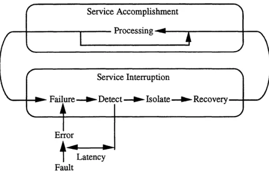
2.1 Fault-Tolerance TerminologyA good starting point for a discussion of fault-tolerance in computer systems is a description of what faults are and how they occur. A computer system is composed of multiple modules, each of which has a certain role. Any given module must operate in a certain manner, which is usually classified in terms of providing certain outputs for certain inputs. This is termed the specified behavior of the module. Any departure from the specified behavior in the actual behavior of the module is designated a failure. The cause of a failure is an uncompensated error, and such an error occurs due to afault. The time delay between the occurrence of a failure and the detection of the failure is the
latency of the error. This chain of cause-and-effect can be best understood through an
example. Suppose there is a fluctuation in the power supply for a memory module. Further, suppose that this fluctuation causes corruption of some of the data stored in the memory module. The fluctuation is a fault, and the corrupted data is an error. When another module accesses the erroneous data, a failure can occur. The time elapsed between the power fluctuation and the data access is the latency of this error. The goal of a fault-tolerant computer system is to mask or otherwise endure the effects of the power supply fault, such that the observed behavior of the overall system does not deviate from the expected behavior.
Figure 2.1 explains this terminology graphically. When the actual behavior of a module matches its specified behavior, the module is in the service accomplishment state. When a module fails, it moves into a state of service interruption. In this state, the system moves through periods of fault detection, isolation, and recovery (FDIR) [GS91].
Faults fall into three general categories: external faults, internal faults, and system misuse. External faults include such problems as interference from electromagnetic
radiation, power source interruptions, temperature fluctuations, and physical abuse of the system. Circuit failures and software bugs are examples of internal faults. The third category concerns the correct usage of a system. Designers of computer systems work with certain assumptions in mind concerning the application of their system. If the operator of a system uses it for a purpose other than what the designer intended, under unexpected conditions and in a unanticipated environment, system failure can result.
T
LatencyFault
Figure 2.1: State Transitions in a Fault-Tolerant Computer System.
2.2 Draper Laboratory
Draper Laboratory has a long history of involvement in the design and development of fault-tolerant computers. This history begins in the mid-1950's as Draper researchers investigated the application of highly reliable computers to flight control, guidance, and navigation. One early effort involved designing the Apollo Guidance Computer in the 1960's, which NASA employed to safely control the lunar missions. A significant accomplishment in the 1970's was the development of the flight control computer for a Navy F-8 airplane being configured to fly-by-wire.
From the late 1970's through the 1980's, Draper and NASA expended considerable effort in designing and building the Fault-Tolerant Multi-Processor (FTMP). The FTMP architecture consisted of three sets of three processors and three redundant
memory modules connected to a system bus. The multi-layered redundancy of computation was the central source of fault-tolerance in the FTMP. This machine greatly improved Draper's knowledge and experience with several fault-tolerance design and realization issues [HLS87].
The lessons Draper learned from the FTMP project led into the next major effort: development of the Fault-Tolerant Processor (FTP) in the early 1980's. The biggest change from the FTMP architecture to that of the FTP was the reduction in overall throughput from that of up to four processors to that of a single processor. The FTP was triply redundant like the FTMP, and this redundancy level could be varied due to the
application of a particular FTP system. Two major projects for which Draper employed the FTP architecture were the control computers for the Unmanned Undersea Vehicle
(UUV) and the Seawolf submarine.
Throughout the 1980's and into the 1990's, Draper has committed substantial resources to developing a succession of Fault-Tolerant Parallel Processors (FTPPs). These machines have successfully realized ultra-reliable parallel processing designs. The next direction for Draper's efforts is toward the design of a more widely applicable fault-tolerant computing system: the Beetle project.
2.3 Other Fault-Tolerant Systems
Several fault-tolerant computers have had an impact on the conceptualization of the Beetle computer system. At roughly the same time that Draper designed the FTMP,
SRI International developed the Software-Implemented Fault-Tolerance (SIFT)
computer. These two systems were devised in coincident time frames and with coincident fault-tolerance goals, but with multiple differences in actual design.
The architects of the SIFT computer system implemented all executive functions, or operating system functions, in software. They chose this approach due to their desire to avoid faults caused by hardware failure. Another goal of the SIFT project was transparency of fault-tolerance. The designers intended for the user to program the system in the same manner as a simplex, or uni-processor, system yet have the benefit of increased reliability. The redundant processors in the SIFT system were loosely synchronized. Unfortunately, with these strict specifications and the limited hardware capability and software tools available at the time, such an implementation of fault-tolerance was far too taxing on system resources. In fact, in some cases, the overhead of fault-tolerance consumed up to 80% of the overall processing time of the machine
[PB86].
The designers of the FTMP had different ideas about how to approach fault-tolerance. They decided to use hardware implementation for some executive functions, such as clock synchronization and voting. This reduced overhead, but required the development of custom hardware. The different modules of the FTMP were tightly synchronized, in contrast to the SIFT system [HSL78]. The result was a slightly more efficient design, but one that was still not practical. The system overhead experienced in the FTMP was roughly 30% of the available processing time [Lala86].
The Multicomputer Architecture for Fault-Tolerance (MAFT), developed at the Allied Signal Corporation in the mid 1980's, followed both SIFT and FTMP
chronologically. MAFT employed loose synchronization, and implemented executive functions with specialized hardware called operations controllers. This computer was capable of handling the control of tasks occurring up to 350 times per second [KWFT88]. By way of comparison, the SIFT architecture was only able to handle control loop frequencies of about 30 cycles per second [PB86].
The SIFT project, in particular, had several then-groundbreaking goals in common with the Beetle project. These included transparency of fault-tolerance to the user and software implementation of fault-tolerance. Therefore, a major challenge for the
Beetle is to meet these goals without the severe performance overhead associated with the
SIFT operating system. A multi-step approach integrated into the design process enables the Beetle to avoid such complications. First of all, the Beetle employs efficient algorithms for the purposes of synchronization, voting, and interactive consistency. These algorithms make minimal use of system resources to accomplish their duties.
Secondly, we measured and evaluated overhead at multiple stages of the development process, in order to monitor system performance. In this way, we largely avoided potential bottlenecks and inefficient implementations. Lastly, the Beetle is not particularly intended for high throughput or highly time-critical applications. An example of how this impacts the system architecture is that synchronization in the Beetle may occur less often than in these previous systems, without jeopardizing the capability
to successfully perform the assigned tasks.
2.4 Byzantine Resilience
Ever since computer scientists first investigated fault-tolerant computing systems in the 1950's, the need for the certification of these systems has existed. The classical method developed and used for many years is termed failure-mode and effects analysis (FMEA). This process involves determining the different possible modes of failure, calculating the probability associated with each mode, and designing tolerance of the most probable failures into the system. The reliability of the system then depends on the likelihood of failure modes which are unaccounted for by the tolerance mechanisms. As
demands for failure rates decrease below 10-9 per hour [HL91], the requirements in time and cost that an FMEA-based approach demand become ever more unrealistic. It became
generally apparent to the scientific community that a new basis for fault-tolerant certification was necessary.
Aside from unrelenting consumption of resources, another problem with FMEA is that it depends upon the correct prediction of all possible faults. If a fault situation is not
foreseen by the system designers, it may not be tolerated. Almost all faults are, in fact, predictable by competent investigators. The possibility still exists, however, for strange and arbitrary faults to occur. Several documented cases of such arbitrary failures exist in the literature. Investigators have traced at least one in-flight failure of a triplex digital computer system to an apparently Byzantine fault and the lack of architectural safeguards against such faults [MG78]. In circuit-switched network studies at Draper, designers observed a failure mode in which a faulty node responded to commands addressed to any node [HL91]. These instances underscore the need for a fault-tolerance certification technique which accounts for arbitrary failures.
Out of these needs, three researchers developed the concept of Byzantine resilience. The initial statement of this new approach comes from a paper by Lamport, Shostak, and Pease [LSP82]:
Reliable computer systems must handle malfunctioning components that give conflicting information to different parts of the system. This situation can be expressed abstractly in terms of a group of generals of the Byzantine army camped with their troops around an enemy city. Communicating only by messenger, the generals must agree upon a common battle plan. However, one or more of them may be traitors who will try to confuse the others. The problem is to find an algorithm to ensure that the loyal generals will reach agreement.
The generals are the processors of the computer system, and the messengers are the communication links between the processors. Note that a faulty processor is referred to as traitorous; this indicates that Byzantine resilient systems can tolerate even intentionally malevolent behavior on the part of faulty processors.
In the following years, others have added to and extended this theory, and several papers have identified the specific hardware requirements to which Byzantine resilient systems must adhere. A multi-processor system is designatedf-Byzantine resilient if it is designed to handle f simultaneously active Byzantine faults. These theoretical requirements are expressed in terms of f. Byzantine resilient systems can either use authenticated message passing or not. Authenticated message passing utilizes unforgeable digital signatures to remove the possibility of one processor forging or altering messages from other processors. Table 2.1 outlines the hardware requirements for both authenticated and unauthenticated message passing protocols. Examination of this table reveals that implementing message passing with digital signatures certainly results in hardware savings and in reduction of complexity.
The processor requirements for Byzantine resilient systems are such that more than two-thirds of the processors must be operating correctly if authenticated protocols
are not used. If the message passing incorporates digital signatures, then greater than half of the processors must be non-faulty. This translates into a hardware savings of f processors.
System Characteristic Unauthenticated Messages Authenticated Messages
Processors [LSP82] 3f+1 2f+ 1
Connectivity [Dol82] 2f+1 f+1
Communication Rounds [DS83] f+1 f+1
Table 2.1: Hardware Requirements forf-Byzantine Resilience.
Consider the distribution of single-source information amongst the processors of the system. With unauthenticated communication, each processor needs 2f + 1 links, since the only way of screening out corrupted or incorrect messages is by a majority vote. If at most f messages can be incorrect, then the remaining f + 1 will be correct and be in the majority. Using authenticated communication, however, the f corrupted messages are easily identified, and the one message that does authenticate can be used. This results in a connectivity requirement of f + 1 for systems using authenticated message passing. A system using authentication protocols requires f fewer communication links than a system with unauthenticated protocols.
When a processor wishes to communicate data to each of the other processors, multiple rounds of message transmission are generally required. Each processor's actions within a given round depend upon the information it received in the previous round. The number of communication rounds required to accurately disseminate information does not change with the implementation of an authenticated message passing protocol. The number of rounds must be f + 1 in both the authenticated and non-authenticated cases.
3.
The Beetle
3.1 Descent from Previous Systems
The Beetle architecture differs fundamentally from systems previously developed at Draper in several important ways. These earlier systems were high cost, highly specialized systems. Some were designed for high throughput, and most were physically large systems. The fault-tolerance of these systems, meaning tasks such as synchronization and voting, was implemented through the use of specialized hardware. All of these goals and characteristics are changed in the Beetle.
Draper has conceived of and designed the Beetle as a low cost, physically small, low power, low weight computer system. One consequence of these specifications is that when compared to other Draper systems, the Beetle has relatively lower throughput for a given processor technology. Also in accordance with these goals, we have implemented the fault-tolerant synchronization and voting algorithms in software to avoid the use of dedicated hardware, which reduces size, power consumption, and weight. Whereas Draper built prior systems such as FTMP with specific applications in mind, the Laboratory intends the Beetle for a very wide range of applications. The Beetle is capable of supporting industry standard operating systems, which allows the end users to program the Beetle in the way they wish and to run their chosen applications. With this goal of wide applicability in mind, we have designed Beetle explicitly for cost versus performance scalability. For example, this would enable the substitution of more powecrful processors for the ones in the prototype. The resulting system would be more expensive, but would also be capable of greater throughput. The idea is that each system can be shifted along the price-performance curve to suit the needs of the individual user.
3.2 Beetle System Description
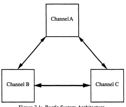
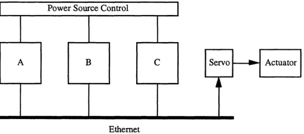
Three processor boards and the associated inter-processor communication links comprise the hardware of the Beetle system. A generalized block diagram of this basic architecture appears in Figure 3.1. Throughout this thesis, we will often refer to the different processors by the letters A, B, and C for the purposes of clarity. The actual hardware and software running on each channel is completely identical (except for a very small amount of authentication information, as we explain in Section 4.1). The communication links are bi-directional, enabling simultaneous two-way transmission.
ChannelA
l~~~~~~~~~~
- 2
Figure 3.1: Beetle System Architecture.
A key concept to understand is how processors in the Beetle system pass various data values between themselves. The Beetle reads values from sensors, uses these values
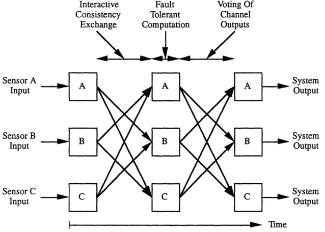
as inputs to calculations, and then votes to determine system output. Figure 3.2 describes
how and when these values are communicated from one processor to another within a single one of the tasks depicted in Figure 1.1.
When viewing Figure 3.2, keep in mind that an arrow from one channel to another
signifies the transmission of data between the two channels. However, this transfer does not necessarily occur in a single message. In particular, the Beetle interactive consistency exchange requires two rounds of message passing between neighboring channels, and the Beetle voting process requires a single exchange round.
As stated previously, one of the design choices for the Beetle involved implementing fault-tolerance in software instead of hardware. One reason for this decision is to provide a fair amount of flexibility in terms of choosing what processors to use for the individual channels. Once we have developed source code for fault-tolerance on the prototype, changing the underlying hardware configuration should be relatively straightforward. We can simply exchange the existing processor boards for ones containing different processors, and then re-connect the communication links. Most of the code developed for the prototype should not be hardware dependent, and only the small amount that is hardware dependent will require modification. Certain sections of the code also depend on the type of operating system being used, and will need to be
Channel B Channel C
changed if the operating system is changed. Effecting these minor changes will also require recompilation of the source code.
Interactive Consistency Exchange Fault Tolerant Computation
A1<
Voting Of Channel Outputs I TimeFigure 3.2: Single Task Information Flow in the Beetle.
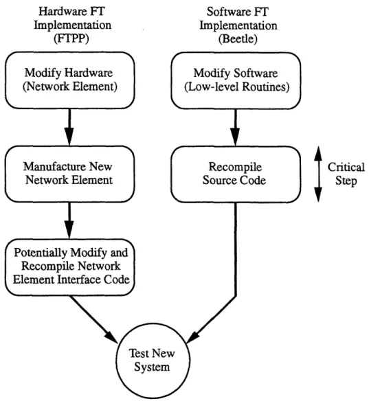
This is in stark contrast to the hardware implementation of fault-tolerance in prior Draper systems, such as the Fault-Tolerant Parallel Processor (FTPP). If the designers wished to change the underlying hardware in such a system, then the dedicated fault-tolerant hardware (e.g., network elements in an FTPP) would also need to undergo revisions. Additionally, in the specific case of the FTPP, updating the type of processor used in the system would necessitate recompiling the interface software for the network elements. From an effort standpoint, it is much more difficult to develop a new piece of hardware and have it manufactured than it is to change a few lines of source code and recompile. Figure 3.3 illustrates this tradeoff between hardware and software implemented fault-tolerance.
To summarize, revision of the Beetle system requires mere software
recompilation, while systems using hardware fault-tolerance mechanisms demand hardware redesign. The slight modifications needed for the dedicated fault-tolerant
Sensor A Input Sensor B Input Sensor C Input System Output System Output System Output
hardware are far more difficult and time-consuming to implement than the slight modifications needed for the software implementation of fault-tolerance.
Hardware FT Software FT
Implementation Implementation
(FTPP) (Beetle)
Modify Hardware Modify Software
(Network Element) (Low-level Routines)
Manufacture New Recompile Critical
Network Element
I auacueNw e~mieII
Source Codec i i a
StepPotentially Modify and Recompile Network Element Interface Code
X ~~~~~~~~~A
System
Figure 3.3: Fault-Tolerant System Revision Process.
3.3 A Reduction in Complexity
In Section 2.4, we enumerated the specific hardware requirements for varying degrees of Byzantine resilience. We now turn our attention to the requirements as specifically applied to the Beetle architecture. The Beetle is designed to be 1-Byzantine resilient, meaning that it is capable of tolerating a single fault of any sort. Examining Table 2.1, and taking the value of f as 1, we see that a system which utilizes
authentication protocols (such as the Beetle) requires three processors, one fewer than the
four required for a system based on unauthenticated message passing. An
communication links, as compared to three for each processor in an unauthenticated system. Therefore, the total number of inter-processor links falls from six to three. So a traditional 1-Byzantine resilient fault-tolerant computer demands more hardware than the Beetle does, for the same degree of fault-tolerance.
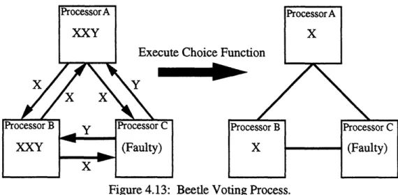
An architecture which compares easily to the Beetle architecture is that of Draper Laboratory's FTPP. The FTPP is composed of several parallel processing groups of four processors apiece; each group is 1-Byzantine resilient. Figure 3.4 demonstrates these hardware reductions by contrasting a single FTPP processing group with the Beetle architecture.
IxI
/\
P,M,I/O
Quadruplex Processing Group of the FTPP
NE: Network Element M: Memory
P: Processor I/O: Input/Output
Figure 3.4: Beetle Hardware Reductions.
There is another major hardware reduction involved in the Beetle architecture as compared with prior Draper systems. The Beetle, with its fault-tolerance implemented in software, does not require the extra hardware of the FTPP network elements. Figure 3.4 also depicts this fact. However, authentication does not affect the number of communication rounds needed for Byzantine resilient interactive consistency exchanges; systems using authentication require two rounds, the same as those systems that do not
use authentication.
We shall now discuss in more detail the connectivity requirement for the Beetle system. According to Table 2.1, the connectivity of the system must be two. This means
P,M,IO NE . P,M,I/O NE P,M,I/O NEPM, P,M,1/O NE P,M,I/O P,M,I/O - 1 * A v , I I% *
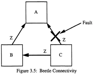
that there must exist two disjoint paths between any pair of processors. This requirement is met by the topology of the Beetle architecture. Figure 3.5 demonstrates the reason for this multipath requirement.
Fault
Figure 3.5: Beetle Connectivity
Suppose that processor C wishes to send the message Z to processor A. Processor C attempts to use the direct link, but a fault occurs in the sending of the message. However,
the path C-B-A is working correctly and processor C can easily send the information to
processor A in this manner. Note that processor A can determine the existence of a faulty communication link, and therefore the incorrectness of a received message, due to the Beetle authentication protocols.
We have already discussed in Chapter 2 what a fault is. We will now discuss how to count multiple faults, and exactly what meaning the value of f has in the hardware requirements table. This issue gives rise to the concept of a fault containment region (FCR). An FCR in the Beetle consists of one processor and its outgoing communication
links. The Beetle has a total of three FCRs. Each FCR is a region of independent power
sourcing and clocking, and each FCR is physically and dielectrically isolated from all of the other FCRs. The failure model used in the literature to specify the hardware requirements for Byzantine resilient systems counts all faults occurring in a single FCR as a single fault. Therefore, f = 1 for the Beetle system means that one FCR is faulty, and the faulty output of that FCR can be due to any number of faults within the confines
of that specific FCR. The important concept from a system point of view is that the FCR
acts faulty at its boundaries. Figure 3.5 demonstrates the extent of each FCR on the Beetle.
The FCR model is also the basis for the various fault-tolerance algorithms which
own virtual clock, which is updated by the fault-tolerant synchronization algorithm. Each
FCR is guaranteed to have bitwise identical inputs by the interactive consistency algorithm, executes the same operations on the input data, and therefore should have the same output. In the presence of faults, a certain FCR may have incorrect outputs, which will be detected by the voting algorithm. We discuss these algorithms in detail in
Chapter 4.
FCR 2
FCR 3
Figure 3.6: Extent of Beetle Fault Containment Regions.
3.4 Target Applications
The Beetle is not intended for high-throughput purposes. Instead, applications requiring moderate performance and high-reliability are the target for this architecture. Using current (1995) processor and communication technology, we believe that the Beetle is appropriate for applications where system inputs are sampled at 1Hz or 10Hz, as opposed to 100Hz. The most apparent type of application for the Beetle is as a slow embedded controller. Characteristics of embedded controllers include the capability to handle large amounts of sensor and actuator input and output, small size, power, and cost, highly integrated processors, and the lack of need for high throughput. All of these are true about the Beetle architecture.
4.
Theoretical Foundations
4.1 Authentication
4.1.1 Overview and Motivation
The use of authentication protocols is the single most important feature of the Beetle architecture. The decision to use digital signatures to sign and authenticate inter-processor messages has significant effects on every stage of the system design. All Byzantine resilient algorithms for authentication systems make assumptions which the chosen authentication protocol must satisfy. The assumptions are these:
1) The sender's signature cannot be forged.
2) Any alteration of the message-signature pair can be detected by the receiver. 3) The receiver can verify the authenticity of the sender's signature. [LSP82]
No chosen protocol can absolutely assure compliance with these assumptions, due to the manner in which digital signatures operate. There is always a finite chance of a malignant channel randomly generating a sequence of bits which will pass the verification test of a receiving channel. However, a properly chosen protocol will make the probability of such an event almost infinitesimal.
Let us examine how these assumptions come into play through a series of examples. In these examples, we shall consider the case where processor A sends a message to processor C. However, processor B must relay the message from processor A t, processor C. This affords processor B with an opportunity to modify the contents of the message-signature pair. If the signatures of all channels are the same, then a faulty processor can easily cause the downfall of the authentication protocol. Figure 4.1 demonstrates this possibility.
M, S M', S
Processor B alters the contents of the message from M to M', and then signs the
message with S. Since signatures are not unique to specific processors, this new signature produced by processor B is identical to the signature that processor A had generated. The result is that processor C cannot determine that the message has been
changed and must accept the message as having been sent by processor A. This problem
is correctable by assigning each processor its own specific signature, as Figure 4.2 displays.
Figure 4.2: Detected fault with processor-specific signatures.
This time when processor C receives the message-signature pair which processor A has allegedly spawned, it immediately notices that the signature belongs to processor B. Processor C then determines that one of two events has occurred: either that processor B signed the message, not processor A, or that the message-signature pair was
corrupted in transmission. In either case, there is no chance that processor C will treat the
message as having been correctly signed by processor A. We therefore show that processor signatures need to be unforgeable, and thereby validate the existence of the first assumption.
However, relying solely upon processor-specific signatures is not sufficiently robust for our purposes. Processor-specific messages prevent faults of the sort depicted in Figures 4.1 and 4.2, but our protocol must detect other possibilities. For example, suppose that processor B alters the message, while leaving processor A's signature untouched. With signatures that are only processor-specific, the signature is still valid, and processor C incorrectly accepts the message. Figure 4.3 illustrates an example of this type of fault.
Figure 4.3: Undetected fault due to non-message-specific signatures.
There is a way to deal with this, however. The solution is to force signatures to be
signature produces variations in the signature for different messages. This scheme easily prevents the aforementioned type of error, as Figure 4.4 shows.
Figure 4.4: Detected fault with message-specific signatures.
Processor C rejects the faulty message M' because the original signature from processor A does not match the corrupted message with which it arrived. Processor C therefore detects the fault. This example confirms the need for the second and third assumptions in our list. With processor- and message-specific signatures, the receiving processor can easily detect any alteration of the message-signature pair it has received (2). To do this, the receiver must be able to verify the authenticity of the sender's
signature (3).
There is another requirement that the authentication protocol selected for the Beetle system must fulfill, and that is to make message signatures be time-specific. The protocol accomplishes this by requiring that every processor include in each message it sends a sequence number, which indicates the relative time at which that processor originated that message. Let us examine how this concept can be useful.
Another possible fault that could occur in the transmission of our example message is that processor B delays relaying the message to processor C for some length of time. In the interim, a message which originated with processor A after the delayed message makes its way to processor C. Processor B then sends the delayed message along to processor C. This out of order receipt of messages can certainly cause problems for processor C, and must be detected. Figure 4.5 gives an example of such a situation.
Figure 4.5: Undetected fault due to non-time-specific signatures.
Processor C receives the second message (M2) before the first (M1), but has no way of knowing this fact. Neither the contents of the messages nor their signatures have been altered in any way, so processor C could have problems if the information in the messages is of a sequentially-dependent nature. There is a solution to this problem,
namely to attach monotonically increasing sequence numbers to each message. Figure 4.6 demonstrates the effects of this information.
Figure 4.6: Detected fault with time-specific signatures.
Now processor C compares the sequence number of the incoming message from processor A to the sequence number most recently received from processor A. If the new sequence number is larger than the previous one, processor C accepts the message (providing, of course, that the signature is also correct). In the example above, when processor C compares the sequence number of M1 to the sequence number of M2, it immediately realizes that the messages are out of order. Processor C then takes steps to re-order, discard, or otherwise deal with these interchanged messages.
We have thus determined the characteristics that the Beetle message authentication system must possess. Following an extensive investigation by Anne Clark,
[C194] is the chosen Beetle authentication protocol, a public key cryptosystem which incorporates sequence numbers. We discuss the specifics of this system in Section 4.1.3.
4.1.2 Origins
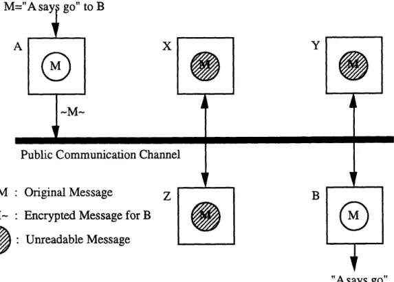
The idea for and terminology of public key cryptosystems originates in a seminal paper by Diffie and Hellman [DH76]. The generalized problem to which the authors propose a solution is that of providing secret communications over an unsafe channel. In a public key cryptosystem, each participant has an enciphering key and a deciphering key. The enciphering keys of all participants are globally available to all other participants (public), and a participant's deciphering key is known only to that participant (private). All participants have access to the same public communication channel. When participant A wishes to send a message to participant B, participant A encrypts the message using participant B's enciphering key and sends the message across the public communication channel. This allows all participants access to the encrypted version of the message, but only participant B can decipher the message and read the contents. We
will refer to this type of public key cryptosystem as Type I. Figure 4.7 depicts a Type I
X
M
-M-B
"Asays go" Figure 4.7: Generalized Type I public key cryptosystem.
The following excerpt from Diffie and Hellman's paper contains a more formalized definition of a public key cryptosystem.
A public key cryptosystem is a pair of families {EK }Ke{K} and {DK }Ke{K of
algorithms representing invertible transformations,
EK:{M} -> {M} DK:{M} ({M}
on a finite message space {M}, such that
1 for every key K E {K}, EK is the inverse of DK,
2) for every K E {K} and M E {M}, the algorithms EK and DK are easy to compute,
3) for almost every K e {K}, each easily computed algorithm equivalent to DK is computationally infeasible to derive from EK, and
4) for every K E {K}, it is feasible to compute inverse pairs EK and DK from K. [DH76]
The third condition is very important, since it makes possible the public revelation of the enciphering keys without compromising the security of the deciphering keys. Rivest, Shamir, and Adleman at M.I.T. invented the first widely accepted system (known as RSA encoding) which met the conditions specified by Diffie and Hellman [RSA78].
A.
4.1.3 Beetle Implementation
The public key cryptosystem we actually employ in the Beetle system differs from the original system described by Diffie and Hellman in several very important ways. In Diffie and Hellman's system, the sender of an original message (the plaintext) performs encryption using the public enciphering key of the intended recipient. The sender then transmits this encoded result (the ciphertext) across an insecure
communication link. Once the message reaches its destination, the receiver translates the
ciphertext back into the plaintext through use of its private deciphering key. In this way, it is possible only for the designated receiver to read the contents of each message. However, there is no means available in this system for preventing one participant from masquerading as another. Each message has only one possible recipient, but many possible originators.
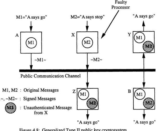
In the Beetle system, which is a fault-tolerant system, we place a premium upon being able to prevent exactly this type of malicious behavior. The very idea of one processor pretending to be a different processor is a typical example of a Byzantine failure. The examples of section 4.1.1 illustrate the possible complications graphically. The Beetle requires a scheme in which each message has only one possible originator, and many possible recipients. We will refer to this type of public key cryptosystem as
Type II. Figure 4.8 shows a general system of this type.
Implementation of message passing based upon a Type II public key cryptosystem involves switching the roles of the public and private keys, as compared to their roles in a Type I cryptosystem. Each processor in the Beetle system has access to all of the deciphering (public) keys, and to its own enciphering (private) key. Therefore, in the Beetle triplex, processor A's signature can only be generated by processor A (i.e., only processor A can encipher a message using its private key), and both processors B and C can easily verify that it was indeed processor A that sent the message.
Another important point to mention is that messages in the Beetle system are signed, and are not themselves encrypted. An actual transmission between two processors involves sending first the unencrypted message, then the associated signature. This means that the data in Beetle messages are not protected from being read by any processor, but that a processor can confirm the source of any message. Secrecy is not the goal in this system; integrity and authenticity are. Figure 4.9 diagrams how the Beetle authentication system operates between any pair of processors.
Faulty Processor Ml="Asays go"
A
M2="A says sto "A says go"
X
Ml, M2
~Ml-,
-M2-Public Communication Chanr
: Original Messages z : Signed Messages
Unauthenticated Message from X
Figure 4.8: Generalized Type
"A says go" "A says go"
II public key cryptosystem.
The sender A signs the message M with its signing function, SA . The private key
for processor A provides the basis of this signing function. The result is the signature S, which processor A appends to the end of M. The sending processor A then transmits the unencrypted message M and the signature to the receiving processor B. To authenticate the message, processor B puts the signature through processor A's checking function, CA. The public key for processor A provides the basis of this checking function. Processor B will accept the message if and only if the signature authenticates.
<M, S>
Communication Link
Sign with S=SA(M) Authenticate with CA(S)=M
Figure 4.9: Beetle Authentication System.
B
Sender A Receiver B
The signing and checking functions used in the Beetle system are 32-bit modular multiplications. The public and private keys are 32-bit numbers with a special property: they are 32-bit modular inverses of each other. The modular multiplication of these two keys will therefore yield a product equal to one. To generate a signature for a message, the signing function first calculates the 32-bit checksum of the message. The signing function then multiplies the checksum and the private key together, and uses the resulting
product as the signature.
The following equations formally describe this process. P is the private key,
P-is the public key, C P-is the calculated checksum of the message, and S P-is the signature.
P P- (mod232) = 1 (4.1)
S=C P(mod232) (4.2)
S P- (mod 232) = C P P-l(mod 23 2) = C(mod 232) (4.3)
Equation 4.1 expresses the modular inverse relationship between the public and private keys. In Equation 4.2, a modular multiplication of the checksum and the private key generates the signature. Equation 4.3 describes the process which the checking function executes upon the received signature. The checking function performs a modular multiplication of with the signature and the public key, leaving only the checksum behind. If this checksum computed from the signature matches the checksum which the checking function calculates from the bits of the received message, then the message authenticates. The receiving processor then accepts as valid the actual information contained in the message.
4.1.4 Finding 32-bit Modular Inverses
We need a method for calculating the three pairs of 32-bit modular inverses required by the Beetle. Our selected method employs an extended version of Euclid's algorithm for calculating the greatest common divisor of two numbers, which Donald Knuth describes in The Art of Computer Programming [Knu69].
Euclid's algorithm determines the greatest common divisor of two numbers. The extension devised by Knuth calculates two more related values. The greatest common divisor of two numbers can be expressed as a linear combination of the two numbers themselves. If the two numbers are u and v, then
u u' +v v' = gcd(u, v), (4.4)
where u' and v' are the weighting factors applied to u and v, respectively. We can use this to calculate modular inverses in the following manner. Set v equal to the modulus (232 in this case), and set u equal to a prospective 32-bit key. Then employ the extended algorithm, thereby determining the value of the greatest common divisor, as well as the values of u' and v'. If the gcd(u,v) is 1 and if u' is a positive number, then we have
found a modular inverse pair. One key is u, and u' is the other. The number v' is of no
interest in this application. The algorithm guarantees that
u u' (mod 232) = 1, (4.5)
which is Equation 4.1 with different notation. We generated the public and private keys for the Beetle prototype with a computer program in C employing the extended algorithm in this manner. Table 4.1 displays the specific numbers for the implementation.
Private Ke Public Ke Channel A 2a569ef9 701dc349 Channel B 3642610b 298262a3 Channel C cfleed0f 4cd261ef Table 4.1: Beetle Private and Public Keys.
4.1.5 Robustness
These signing and checking functions based on modular multiplication do not provide an ultra-secure cryptosystem. In particular, this method does not satisfy condition 3 as set forth by Diffie and Hellman. Knowledge of the public key of a certain channel, and knowledge of the modular multiplication scheme, allows a malicious channel to calculate the private key of the other channel. The private key can be found easily enough by applying Euclid's Extended Algorithm in a reverse fashion, to find the 32-bit modular inverse of the public key. As mentioned previously, a method such as RSA would correctly meet the conditions specified by Diffie and Hellman.
So why does the Beetle system use a less secure cryptosystem? The signing and checking scheme of the Beetle authentication system is efficient, requiring less computation time than more robust RSA-type methods. RSA would be more secure, but would require more overhead time, and in this particular system, we have resolved to keep fault-tolerance overhead to an absolute minimum. The present system is effective against random faults, but is vulnerable to attacks from faulty channels which have cryptanalytical capabilities. Ralph Galetti discusses the robustness of this scheme in
further detail in his M.I.T. Master's thesis [Ga190].
4.2 Clock Synchronization
4.2.1 Overview
As we described in Chapter 1, the key idea behind fault-tolerance in a distributed system is that redundant channels are provided with identical inputs and execute identical instruction streams. Then the system votes the various channel outputs to determine its overall output. To accomplish these goals, it is necessary for the individual channels to be synchronized with each other. In fact, fault-tolerance cannot be achieved in an
asynchronous system, as mentioned in Section 1.2. In the Beetle system, this means that
each channel maintains a virtual clock which is synchronized to within a known skew of the virtual clocks of each of the other two channels.
4.2.2 Key Synchronization Issues
All processor boards on the market today include at least one, and most often, more than one crystal oscillator. The vibrations of these crystals are extremely regular in nature, and are used to generate the various clocking signals required by the board. These oscillations are also used to generate consistent processor interrupts of a constant frequency, to accommodate various timing functions needed by the operating system and possibly the user. Creating and updating a virtual clock for the purpose of task scheduling and fault-tolerance is exactly such a user process.
In the Beetle prototype, we designate the time between successive timer interrupts generated by one of the on-board oscillators as the least significant "bit" of the virtual clock. Each of these time slices between interrupts, which are generally on the order of
milliseconds, is termed a "tick," and the virtual clock tracks time in ticks. However, these
implementation. They will merely trigger interrupts by their natural oscillations, which cannot be affected by the user. We could initially synchronize the timer interrupts themselves, but we do not do this in the Beetle system for reasons involving portability between operating systems and development costs associated with the time needed to implement such a synchronization. Therefore, the timer interrupts occur at different times on different channels. Figure 4.10 presents these concepts visually. Notice that the length of a tick on all three channels is (almost exactly) the same. Also note that, although in the figure timer interrupts occur in the same relative order across the channels each time, due to clock drift, this is not the case over a long period of time.
Ticks C.r T,r to
A
B I
C
111liI lLi -LUL
I I
I I I I
Time Figure 4.10: Timer Interrupts on the Beetle.
When the user powers up the system, the virtual clocks are initially synchronized. That is, at a given point in real time, the next timer interrupt on each of the three channels is designated as the start of the first clock frame and the tick counter is reset to zero. From that time forward, every occurrence of a timer interrupt causes the tick counter to be incremented by one. Once the virtual clocks have been initialized, it is up to the chosen synchronization algorithm to keep them synchronized. Clock frames are intervals which consist of a certain number of ticks, during which the system schedules the execution of fault-tolerant tasks.
Our present initial synchronization method is not fault-tolerant; that is, a single faulty communication link can ruin the process. To accomplish a fault-tolerant initial synchronization, we will eventually implement an extended version of the current clock synchronization algorithm. This extension allows new processors to join the currently synchronized group [HSSD83].
Another issue which we must consider is clock drift. The crystal oscillators are not perfect; that is, there is a very small but finite amount of deviation in the time
between successive oscillations. Due to this drift, the interval between timer interrupts is not exactly constant, and therefore the time as registered by the virtual clocks will also drift. This is the critical reason for periodic resynchronization. In addition, this means that the skew between virtual clocks will be constantly shifting. Clock skew between channels is therefore not a constant, and can only be characterized in terms of a minimum, maximum, or average. Figure 4.11 depicts clock skew between the channels
in the Beetle system.
Ž .~"'~'~2.... (54'.L'...
T
Clock Frame n-.l Clock ' Frame
T.,1_., A Tt,,., A
Clock Frame n-I | Framen
TskewBC
C Clock Framen-i .Clock Frame n .
Figure 4.1 1: Clock Skew Between Channels.
The values of Tskew in Figure 4.11 are constantly changing between every synchronization. In fact, oscillator drift is enough of a factor that over a long enough period of time, the relative ordering of the virtual clocks on the three channels can
change.
4.2.3 Synchronization Algorithm
To synchronize the three Beetle processors, we employ an algorithm described by Halpern, Simons, Strong, and Dolev [HSSD83]. This algorithm provides a method for maintaining the synchrony of virtual clocks in distributed systems, using authentication to guarantee the validity of inter-processor messages. The algorithm makes use of three major assumptions, which we shall discuss.
For the purposes of this algorithm, we note the difference between Newtonian
time, which is unobservable real time, and clock time, which is the time as measured on
the virtual clock of a processor. The virtual clock Ci(t) represents the virtual time on
processor i's clock at real time t. A correct clock has a rate of drift from Newtonian time
A
B