Diaphragm Forming:Innovation and Application to
Ocean Engineering
by
Gilles Langlois
Diplome d'ing6nieur
Ecole Nationale Sup rieure de Techniques Avancees, June 1993
Option Architecture de Systhmes Navales
Submitted to the Department of Ocean Engineering
in Partial Fulfillment of the Requirements for the Degree of
MASTER OF SCIENCE IN OCEAN ENGINEERING
at the
MASSACHUSETTS INSTITUTE OF TECHNOLOGY
September 1994
@ 1994 Massachusetts Institute of Technology
Signature of Author:
Certified by:
Certified by:
Accepted by:
De artment of Ocean Engineering August, 1994 Dea • o ° y G. Gutowski Professor, Department of MeNhanical Engineering Thesis Supervisor •... .. V.. .L buchi
Professor, Department of OceanEngineering
"Tbaci' Rpqdpr
A. Dougla4-Cam iael,
Chairman, DepartmentalGraduate Committee
tment of OceanEngineering
MASSACHUSES INSTITUTE
:OCTIT 499T4
Diaphragm Forming: Innovation and Application to
Ocean Engineering
by
Gilles Langlois
Submitted to the Department of Ocean Engineering On August 6, 1994 in Partial Fulfillment of the
Requirements for the Degree of Master of Science in Ocean Engineering
ABSTRACT
Composite materials have high mechanical specific properties such as strength or stiffness per weight or corrosion resistance which make them very attractive for Ocean Engineering Applications. But these excellent properties compared to those of metals are somewhat undermined because of the prohibitive cost of manufacturing composite parts .This is mainly due to the fact that composite parts are made by a labor intensive hand lay-up process. Automating the development of complex composite parts is potentially a cost effective technique. In terms of cost, one of the most promising of these techniques is the Diaphragm Forming Process. However some undesirable deformation modes such as laminate wrinkling can predominate under certain forming conditions.
The purpose of this study is to concentrate on this laminate wrinkling and see what should be done in order to understand and avoid this undesirable mode. This study will concentrate on increasing the stiffness of the diaphragm by reinforcement (patent pending). This study, also focuses on the applicability of diaphragm forming to Ocean Engineering applications.
A technique for reinforcing the diaphragm using woven wires has been developed. The work involves determining the feasibility of weaving reinforcement from different engineering materials such as Kevlar and steel, evaluating how bad is the indentation problem, where the reinforcements become embedded in the deforming composites, causing surface irregularities, and determining the relationships between the reinforcement orientation, the optimum spacing of the wires and the materials.
Thesis Supervisor: Timothy G. Gutowski
Professor, Department of Mechanical Engineering Thesis Reader: Koichi Masubuchi
Acknowledgments
Sincere thanks go to Professor T. Gutowski for supervising my thesis and providing me the opportunity to work on this project, I also thank Professor K. Masubuchi for his comments and for allowing me to work with his laser microscope.
I would like also to thank Dr. Greg Dillon for his spirit, guidance and advice throughout this project.
Thanks also to Fred for helping me out in the work shop.
In addition, I would like to thank all the students of the lab, for their help and good humor, Sukyoung, Haorong, Ein-teck, and Maurilio.
Finally, I would like to thank the "Direction des Constructions Navales" for sponsoring my studies at MIT.
Contents
List of Figures
1 INTRODUCTION
1.1
Background..
. . . .
. . . .
. . . .
. . .. .
. .15
1.2
Diaphragm forming ...
...
....
..
.. 19
1.3
Thesis Overview
. . . .
.
. . . .
. . . .
. . 21
2 FORMING LIMITS
2.1
Introduction...
....
....
....
.. 23
2.2
Deformation modes . . ....
...
24
2.2.1
Coordinate system. . . .
. . .
. . . .24
2.2.2
Constraints ...
. ...
.
...
...
25
2.2.3
Deformation modes ...
. . . .
. . . .25
2.3
Kinematic analysis ...
..
.
. . . . .
.
. . . 30
2.3.1
Ideal fiber mapping ...
...
30
2.3.2
In-plane Shear .
..
.
. . . . .
. . . 33
2.3.3
Inter-ply shear
...
. . .
. . . 36
2.4
Rheological properties of the material . . . ...
37
2.5
Process analysis ....
...
....
.. 41
2.5.1
Mechanism of supporting the laminate. ...
41
2.5.1.1
Friction transmission . .
. . .
. . 42
2.5.1.2
Support the laminate
. ...
.
. . 43
2.5.2
Forming sequence . ....
. . . .
.
48
2.5.3
Tool heating.
...
...
.... ...
49
2.6
Forming limit diagram .
. . . .
. . . .
. .. .
. . 51
2.6.1
Mechanisms causing Laminate Wrinkling. .
.. 51
2.6.3
Forming limit diagram .
....
....
.. 52
3 DIAPHRAGM FORMING FOR OCEAN ENGINEERING
APPLICATIONS
3.1
Introduction ...
..
.... ...
3.2
Different applications related to diaphragm forming.
3.2.1
Assisting RTM ....
...
3.2.2
Glass reinforced thermoplastics .
. . . .
3.2.3
Forming whole hulls . .
. . . .
. . . .
3.2.4
Forming advanced composite for marine
applications . . . .
. . . .
. . . .
3.3
Design and proof of concept . . .
. . . .
. . . .
3.3.1
Design of the part . . .
. ...
3.3.2
Experimental approach. . . .
4 INNOVATION IN DIAPHRAGM FORMING
4.1
Introduction ...
....
. .
4.2
Exposition of the problem ...
The woven Fabric...
...
The indentation problem . ...
. .
Experimental set-up . ..
. . .
. . . .
Optimization of the fabrics ...
. . . .
4.6.1
4.6.2
Rods . . . . .
. . . .
Effect of the reinforcement size ..
4.6.3
Threads...
....
....
4.7
Effect of reinforced diaphragm forming.
4.8
Design reinforcement for different shapes.
5 CONCLUSION ...
....
BIBLIOGRAPHY ...
....
....
.
65
...
..
75 . . . . . . 76 .76. . . .78
. . . .
.
. 81
81
. . . .
.
.
84
. . . . .
.
87
. . . .89
. . . .
.
.
91
. . . .
92
.
93
.
99
. . . .
103
. 105
* .53
* .54
S.54
. .56
. .57
. .60
. .61
4.3
4.4
4.5
4.6
Appendices
LIST OF FIGURES
Figure 1.1: Figure Figure Figure Figure Figure Figure Figure Figure Figure 1.2: 1.3: 1.4: 2.1: 2.2: 2.3: 2.4: 2.5: 2.6: Figure 2.7: Figure Figure Figure Figure Figure Figure Figure 2.8: 2.9: 2.10: 2.11: 2.12: 2.13: 2.14:Operating depth potential of submersibles
made in different materials ... 16
lay-up of the prepreg in order to get the preform. ... 18
Schematic of diaphragm forming process. ... 19
Illustration of reinforced diaphragm forming... 20
Illustration of the material coordinate system... 24
Between-plane deformation modes of laminated plies.. 26
Out-of-plane deformation modes ... . 27
In-plane deformation modes ... 28
Illustration of trellising behavior of 0/90 woven fabric.. 29
Illustration of first fiber placement in the ideal fiber mapping of a box with round edges. ... -31
Placement of the neighboring fibers on a cube with round edges ... 31
Illustration of a preform for an hemisphere ... 32
Illustration of strain shear of fibers ... 33
Integration domains ... 34
Comparison between actual shear and calculated shear for hemisphere and C-channel. [Li] ... 35
Illustration of inter-ply slippage in the rich resin layer.. 36
Drape test set-up, three point bending apparatus. ... 38
Illustration of the sensitivity of the applied load to the cross-head speed ...-. 39
Figure 2.15: Figure 2.16: Figure 2.17: Figure 2.18: Figure 2.19: Figure 2.20: Figure Figure Figure Figure Figure Figure Figure Figure Figure Figure Figure 2.21: 2.22: 2.23: 2.24: 2.25: 3.1: 3.2: 3.3: 3.4: 3.5: 3.6: Figure 3.7:
Apparent viscosity versus shear rate [Neoh]... 40
Apparent viscosity versus temperature ... 40
Illustration of the laminate being clamped by the diaphragms ... 42
Laser microscope views of the fibers in different ply on the location of a wrinkle. (a) 0 deg ply (b) 90 deg ply (c) +45 deg ply (d) -45 deg ply (magnification X40)... 45
Illustration of the wrinkle patterns of a [0/90/+45/-45]s Toray C-channel ... 46
Illustration of the wrinkle patterns of a [90/90/+45/-45]s Toray C-channel ... 46
Effect of the pressure on the diaphragms. ... 47
Illustration of the forming sequence for the case of the flange of a C-channel ... 48
Illustration of the heating of the laminate. .49 Qualitative illustration of the non-isothermal heating on the stress inside the laminate. ... 50
Forming limit diagram for C-channels of different sizes 52 Trellising deformation of woven fabric draped over a sphere... ... 55
Illustration of FRTM process flow diagram... 56
Illustration of automatic spray-up ... 58
Inflated Tool Forming ... 60
Single skin hull typical stiffener top hat shape... 61
Transversely framed single skin hull ... 62
Figure 3.8: Figure 3.9: Figure Figure Figure Figure Figure Figure Figure Figure Figure Figure 3.10: 3.11: 3.12: 3.13: 3.14: 3.15: 3.16: 3.17: 3.18: 4.1: Figure 4.2: Figure Figure Figure Figure 4.3: 4.4: 4.5: 4.6: Figure 4.7: stiffeners...63
Longitudinally stiffened single skin hull... 63
Illustration of a Top-hat shape intersection cross with sharp ... ... . 64
joining part for different stiffeners sizes. ... 65
Top view and front view of the top-hat shape intersection part... 66
Illustration of the set up of the forming machine... 67
Illustration of the forming of (0/90)s ... 69
Illustration of the wrinkling phenomena for (+/-45) plies... 70
Illustration of the cut out of second set of experiments.-;71 Another design of cuts out ... 71
Effect of the cut-outs on (+/-45) lay-up ... 72
16 plies part formed at 1800C with cut-outs ... 73
Illustration of a C-channel and its structural application as an element of an curved I-Beam... 77
Illustration of the wrinkles patterns (a) on the Web (b) on the back flange ... 78
Shaping assembly ... ... 79
Reinforcement ... 79
Loom ... 80
Illustration of the indentation problem for a two foot long C-channel ... ... 81
Part formed with reinforced diaphragm forming and cured in the autoclave ... 82
Figure 4.8: Figure Figure Figure Figure Figure Figure Figure Figure Figure Figure 4.9: 4.10: 4.11: 4.12: 4.13: 4.14: 4.15: 4.16: 4.17: 4.18: Figure 4.19: Figure 4.20: Figure Figure 4.21: 4.22: Figure 4.23: Figure 4.24:
Laser microscope views of the cross section of part made (a) without reinforcement
(b) with reinforcement.(magnification X40)... 83
Small forming machine ... 85
6 foot long forming machine used for forming 2 foot long and 4 foot long parts ... 85
Forming a part with reinforcement ... 86
Removal of the reinforcement ... 87
Illustration of a typical mild steel fabric ... 88
Illustration of a polyethylene fabric ... 89
Illustration of the effect of reinforcement on the back flange of Toray C-channels. (a) case of thin rod reinforcement (b) case of thick rods reinforcement. . 90 Small reinforcement ... 91
Illustration of the marks left by the small reinforcement92 Forming limit diagram for 1 foot long Hercules C-channel with a [0/90/+-45] lay-up ... 92
Forming limit diagram for 1 foot long Toray C-channels with a [0/90/+-45] lay-up ... 94
Difference between a small Toray C-channel made with reinforcement and without reinforcement. ... 95
Forming limit diagram for 2 foot long Toray C-channels96 Difference between a small Toray C-channel made with reinforcement and without reinforcement. ... 97
Illustration of knit ... 99
Illustration of chopped rods embedded into a rubber m atrix ... 100
Figure 4.25:
Figure 4.26:
Illustration of curved rods embedded into a
rubber matrix ... 101 Illustration of stiff particles embedded into a
Chapter
1
INTRODUCTION
1.1 Background
Since the 1950's, the use of Fiber Reinforced Plastic (FRP) for marine applications has grown substantially. Initially, FRP was used for small crafts only, but now structures having a mass of several hundred tons are being produced. The uses of composites in marine applications range from components like radar domes, masts, shafts and propellers to large ship hulls, ship superstructures and submersibles.
Composite materials are of interest because they provide high strength-to-weight and high stiffness-to-strength-to-weight ratios. Because composite components are lighter they allow an increase in the payload fraction (ratio between the weight of the payload and the weight of the ship) and better stability due to lighter structures above the waterline. Other advantages of composites include good fire protection, low thermal conductivity, good corrosion resistance and design flexibility. It is now possible to manufacture FRP structures which outperform their metal counterparts in term of strength, weight, and cost. This is illustrated in Figure 1.1 which compares the potential
16 CHAPTER 1
operating depth of submersibles made of different materials. (It should be cautioned that this graph is mainly based on strength-to-weigh ratio, no concern was given to fracture toughness, resistance to stress corrosion cracking...) ARCTIC
-ARCIIC
HEGO C E A N ... ARCTIC ----. MEAN DEPTH MAXIMUM DEPTH ATLANTIC ----MARIANAS ... TRENCH PACIFIC Figure 1.1: Operati 0( ng LSS"
10 20 30 40 50 60 70 80 90 100 PERCENT OF LESS THAN INDICATED DEPTHdepth potential of submersibles made in different materials [Masubuchi].
FRP is very competitive on the market of small ships and is confined to vessels below 50 m. The economical viability of welded steel being higher-for vessels over 50 m. The construction of bigger FRP ships could become feasible in term of cost if:
- Material and construction costs are reduced relative to steel. 0 5.000 10,000 15,000 30.000 35,000 '-
L
- .---
'!
HULL WEIGHT -TO.DISPLACEMNT RATIO
NOTE: "IIY" DENOTES YIELD STRNGCTII
ASSUMED IN CALCULATIONS
I I I I I I
A0c~
~Lk~L~\it~i~
s"5~~";";i;iJ
INTRODUCTION 17
- Laminate stiffness is increased to use the potentially high specific strength effectively.
- The use of prefabricated laminates, or closed mold technique increases, because they can eliminate the large environmentally controlled laminating sheds.
Another problem pointed out by some Japanese shipyards is the recycling of these materials which may be a great subject of concern in case of wider uses of FRP. [Masubuchi]
A wide variety of composites are used in marine applications. Cost being a primary driver in the marine industry, most of its composite applications use glass fibers reinforced by polyester or vinyl ester resins which allows a good compromise between price and performance. But some specific applications such as racing boats, submarines, high speed boats , SWATH (Small Water plane Area Twin Hull), SES (Surface Effect Ship) require advanced composite materials, with longer and stiffer fibers, stronger resins and higher fiber contents, which enable larger weight savings, strength increases and performance advantages.
Although composite materials are used in very modern equipment such as aircrafts, satellites, and deep-submersibles, they are manufactured by extremely low technology processes. In fact most parts are manufactured by a hand lay-up process. In this process layers of prepreg material, which is a combination of fibers embedded in an uncured or thermoformable matrix, are placed ply by ply over a tool having the required shape. For complex shapes, this process requires many hours work by skillful operators, and
18 CHAPTER 1
many parts are lost because of manual errors. This increases the cost of composite parts and prohibits wider use.
In order to improve the competitiveness of composite materials over its metal counterparts some new manufacturing processes, which can be automated, have been developed such as filament winding, pultrusion, resin transfer molding, drape forming, matched die forming, automatic tape _and double diaphragm forming. Among these techniques, the diaphragm forming process seems to offer the most cost effective means of producing complex shapes. In this technique, woven fabric, unidirectional thermoset or thermoplastic prepregs, or random chopped fiber mat embedded in a thermoplastic matrix can be used as the based material. In the case of prepreg, strips of materials are laid up in orientations determined by directional stiffness requirements and then trimmed to the preform shape (see Figure 1.2). After the preform is placed between two diaphragms, the whole unit is formed over a tool by application of pressure or vacuum. (See Figure 1.3). After the forming is completed the part is removed from the forming machine and goes through an autoclave cure cycle. The same machine can accommodate a variety of tools.
(i) prepreg (ii) lay up (iii) compaction (iv) preform Figure 1.2: lay-up of the prepreg in order to get the preform
INTRODUCTION 19
diaphragm
(v) assembly (vi) forming process by pulling vacuum under the tool
Figure 1.3: Schematic of diaphragm forming process.
1.2 Research Objectives
Before diaphragm forming can be used in industry the process needs to be studied in more detail in order to avoid undesirable deformation modes like in-plane buckling, fiber spreading, fiber bunching and laminate wrinkling.
One unique feature of this research is that it is aimed at studying continuous aligned fibers embedded into a thermoset matrix. Some experimental work aimed at studying the forming limits determine by the presence of wrinkles has already been carried out. Significant changes in the formability of the composite have been found by varying the composite properties, the part geometry, the diaphragm properties, the temperature, and the forming rate. This work has led to the concept of the Forming Limit
20 CHAPTER 1
Diagram as a design tool for engineering applications. This research shows the limits of the process in terms of the part sizes that can be achieved and points the way to innovations that could extend the process.
The objective of this research is to assess a recent innovation on diaphragm forming which consists of increasing the stiffness of the diaphragm material by reinforcement as shown on Figure 1.4. This technique using woven wires has been developed, tested by the author and included in the forming limit analysis.
Woven Support Fabric
Z
Woven Support Fabric
Figure 1.4: Illustration of reinforced diaphragm forming i
INTRODUCTION 21
Another aspect of this study is to expand the range of parts that can be made by diaphragm forming. A part which is the intersection of two top hat ship stiffeners is design and manufactured. This is a direct application of diaphragm forming to a component of interest in Ocean Engineering.
1.3 Thesis Overview
Chapter 2 describes the forming process for a flat laminate and illustrates its limits. This chapter introduces the different deformation modes, the concept of shear, a basic theory of laminate wrinkling and the concept of a Forming Limit Diagram.
Chapter 3 emphasizes the application of diaphragm forming to Ocean Engineering. This is done by pointing out some applications using glass fibers, and by the design of and experimentation on a cross shape part that can be used to join a longitudinal and transverse top-hat stiffeners used in the marine industry.
Chapter 4 gives an overview of the experimental work which has been carried out by the author and the main results of reinforced diaphragm forming included in the forming limit analysis.
Chapter
2
FORMING LIMITS
2.1 Introduction
The piroble~m of fonrming• flat laminates of continuous fibers into different 4hapes, can be summarized as "inducing desirable deformation modes while s.uppressing the undesirable ones". This chapter is aimed at explaining in more detaii the mechanisms required to achieve this.
Numerous experiments ([Chey], [Monaghan and al.],...) show that the quality of a part is strongly influenced by the process, the material system and the part geometry. And if these parameters are not optimized the part is not acceptable and can undergo undesirable deformation modes, the most serious of wvhich is laminate wvrinkling.
First, wve will examine the fundamental differences between the deformation modes, then, \ve will study the relationship between the part e•,ometrv and the occurrence of undesirable modes from a kinematic point of
\ itC\. A rew issues related to the behavior of the material and its rheology
will be discussed and trends influencing the process will be highlighted. All of these parameters have an influence in the limits of diaphragm forming
24 C('I,4PTER 2
which culminate into the concept of a forming limit diagram. Borrowed from sheet metal forming, this concept is aimed at predicting a priori if the part is achievable with diaphragm forming.
2.2
Deformation modes
2.2.1 Coordinate system
In order tO accouInt ,0r the non-isotropy or composite laminates in our anahlsis w\e define the material coordinate svstem as shown in Figure 2.1.
Figure 2.1: Illustration of the material coordinate system
Axis 1 lies along the fiber direction, axis 2 is transverse to the fibers within the plane of the laminate and axis 3 is perpendicular to the ply (through the
7RMI.VXG L ,I[ITS 25
2.2.2 Constraints
b;ecause f tIke ;',aturCe r advancec comp*osite * repreg, three basic
.!s>ttumition, ii % '1i1ii restrict the way the laminate can deform, must be
<tated.
.l!- The fibers are onsildered inextensible i.e. they do not stretch, or contract LIurin~, t2e arm•inn 2ces
• - The m:',terla~ :natri\ anid :ibers) is incomrressible, the deformation must
- . r ... r : ,, , -2-need t, , . ,i ,,, •ut the ,efo rma tion.
T ,. :,n trains , ,. urih ... , .deai comrosite. ",vhich forms the basis of our
.inematlc lai\i, ii~ • 'rov\ides a standard to which formed parts can be
These three basic assumptions lead to the following consequences: a- Dlesirable detormation modes are in-planes.
b- The local deformation must propagate out to the edge of the ply. This is due to the lack of local plastic deformation which exists in isotropic materials. .As a result, the maximum shear occurs at the edge of the ply.
2.2.3 Deformation modes
The different deformation modes that can be encountered during
forming ihave been categorized as follo\'ws [Tam]:
1. Bet\\een-plane modes (Figure 2.2). The inter-ply slippage shown in
Figures, 2.2.a and 2.2.b is necessary to achieve simple bending, and double
I
---- ·
ID---
26 CHAPTER 2
2. Out-of-plane modes (Figure 2.3). These modes are highly undesirables and the out-of-plane buckling (Figure 2.3.a) is also designated laminate wrinkling.
3. In-plane modes (Figure 2.4). The in-plane slippage described in Figure 2.4.a, is a desirable mode which allows the fibers to conform to double-curvatures. This slippage is usually very difficult to achieve. Transverse shear may occur in an ideal fiber mapping as long as thickness variation does not result. The other deformation modes (Figure 2.4.c,d,e) are undesirable.
k
a) Inter-ply shear b)Inter-ply shear
FORMING LIMITS
SOu t-or-plane buckling (Wrinkling)
1
t'
2--b)Fiber crossing
Figure 2.3: LOut-of-plane deformation modes.
v I **** • e* * ** * *** e*/ * e, / /**** * **0 e **9 ** ·.
3
4:ai Iln-vyan lippag b) Tansvrse hea
.2
2S CHAPTER 2
-- 2
-40
allmC
Lku
c Fiber splitting d) Fiber bunching-up
2
e) In-plane buckling
Figure 2.4: In-plane deformation modes.
For fabrics, another deformation mode known as trellising (Figure 2.5) can occur and replace the in-plane slippage. This gives rise to some deviation from the ideal fiber mapping, because the fibers are not evenly spaced.
FrORIIVG LIMITS 29
N
Figure 2.5: I 0C 4-tra'i'n treilisin, beha\ior or 0 ,0. woven fabric
:L .ei•ormaNIon tOr ::c l-amiiniate is a combination of these nmodes.
The intra-plane -iippae (Figure 2.4.a) and the inter-ply slippage (Figure
2.2.a,b) nmut occur iIn order to alleviate the shear stresses that build up while
the laminate is being deformed. When these modes cannot be achieved,
Lundesirable modes Iuch as laminate wrinkling may occur. The difficulty in
achiet.ving sutficient I:n-pi-Lane slippage or inter-ply slippage arises with double curved shapes. And most of the undesirable modes occur while forming these parts. We will term double curved surfaces as complex shapes. Therefore, it is important to iink the geometry of the part to the deformation mitciles required. This c.a1n be done through a kinematic analysis of an ideal riber mapping. The theoretical in-plane shear can be calculated using the Sau-bonnet thteorem'I. and the inter-ply shear can also be evaluated. We will briefti discuss how thes.e theoretical results deviates from the experimental
3(0 CHAPTER 2
2.3
Kinematic analysis
The fibers are modeled as 3d curves and the laminates as 3d surfaces. The analysis applies the principles of differential geometry.
2.3.1 Ideal fiber mapping
%,ome important results from differential geometry are related to geodesic curves on a surface. A geodesic path on a surface does not have in-plane curvature and so it does not shear relative to its in-plane neighbor. Therefore, during the forming it is better if the fibers follow geodesic paths.
An ideal fiber mapping preserves even thickness throughout the part and therefore even fiber spacing. The method to obtain an ideal fiber mapping is to draw on the shape an initial fiber according to the lay-up orientation required, usually following a geodesic path (See Figure 2.6 for the case of a box with round edges). The mapping is continued by laying down the neighboring fibers and maintaining a constant spacing between the fibers as shown on Figure 2.7).
FORMING LIMITS
Figure 2.6: Illustration of first fiber placement in the ideal fiber mapping or a box with round edges.
Figure 2.7: P!acement of the neighboring fibers on a cube with round
32 C'HAPTER 2
Oince the ideal mapping for a shape is determined it is possible to back calculate and determine the flat preform that is required to make the part with no waste. Figure 2.8 illustrates the shape of a preform for an ideal hemisphere.
(x,y)
tR
O)RAIL\G LL\IITS
2.3.2 In-plane Shear
fiber eliements before and after forming.
.-\ss•~nL the ditance between two fibers is constant, the point B moves a
Mistalce A atie t ts neig!hbor. We can define the in-piane shear as
(2.1)
d
B L
Mui-Figure 2.9: Illustration of strain shear of fibers.
\Ve know that the in-ilane shear is a desirable mode to obtain. We will explain how the in-plane ,hear can be evaluated from the ideal fiber placement. [Tamnj W\e will only quickly overview the more important results.
From differential geometry it is possible to relate the in-plane shear to the
got'de•sic curvature of a fiber by the following relationship [Tamj:
-L
F,1 =
Jl
ds (2.2)' here: I-: :is the i-pilane shear for a given fiber.·
:is the geodesic curvature as a function of distance along the fiber, s.
.: is the lenkgth lof the fiber.
31 I 7 ~ ! o •hole p-arailei ·-:.., -- I
34 CHAPTER 2
And using the Gauss-Bonnet theorem, [Tam] has shown that the magnitude of the shear can be related to the curvature of the surface. The Gauss-Bonnet relation is expressed as follows:
K, .ds + ff, KdA = 2re- i
(2.3)
where K is the Gaussian curvature of a surface, R is a region of the surface bounded Lb a closed curve C made of k smooth arcs having exterior angles Oi,
as shown in Figure 2. 1()0. Cl C,
fiber
C
304
C
4Figure 2.10: Integration domains
By choosing the path C to include two fibers and two orthogonal geodesics as shown on Figkure 2. 10. The shear can be expressed as [Tam]:
FORMING L.IITS 35
- = ds= -ffKdA= -KTR
(2.4)
Therefore it becomes possible to calculate analytically the shear required
:or several simie r&cometries such as cones, hemispheres, and "C" channels.
The !ideal shear can then be compared with the actual shear, measured on a formn' part as >Ii wn of ficure 2.11.
o R=0.53" O R=1.03"
O
R= 3.53" O R=4.53" - Ideal Shear0.0
0.2
0.4
0.6
o.8
1.0
Sn/Sn,max
Figure 2.11: Conmparison between actual shear and calculated shear for hemisphere and C-channel. [Li]
There is a tendenci- for the actual shear to depart from the ideal. This is due to the unev\en thickness distribution over the part. The difference is due to fiber bunching, fiber spreading,, or trellising behavior. It is also interesting to note that the actual shear deviates substantially from the ideal shear near the edges. In fact the ideal fiber placement is almost impossible to achieve for
2.0
1.0
C3
CHAPTER 2
complex shapes, but there are still many chances for the part to be good from a mechanical point of view. The ideal fiber placement gives an idea of what the fiber mapping should be.
2.3.3 Inter-ply shear
Inter-ply shear is the slippage between two plies of different orientations. Inter-pVi shear is accommodated by the resin rich layer present on most Srepre~ •urtaces. (See Fiure 2.12) The resin rich laver is caused by the mecihanlm ot percolation of the resin through the fibers [Barnes and Cogswell] and allows the plies to slide past each other.
h
0
*,go * * * *0*00000**0*09**gee of *
.* * . . ...* *... . .
OoO0 OOOOOO0•O · ~ · ~·~~~·~ ••
Figure 2.12: Illustration of inter-ply slippage in the rich resin layer
We can define the inter-ply shear as follows:
interply = h (2.5)
The inter-ply shear can be orders of magnitude higher than the in-plane shear. The lay-up orientation influences strongly the way the inter-ply shear is achieved. For (0/90) or (+/-45) lay-up the whole laminate behaves similar to a woven material and deforms in a manner similar to trellising. Therefore,
170-RMPING LIMITS 37
they\ are easier to form because they don't require too much inter-ply slippage.
For ! ' .0 1 ~453 -45) la:'-lL. each laver has to move relative to the adjacent one.
The induced inter-,Piv Ihear can be very large, and thus the part is harder to
form than (',)c or --- 45 lav-up.
WVhile characterizin the effects of the piv orientation on the flow process [Scinerr] ha r how :ia finite element anaivses, that the inter-ply slip is easier .r the li~e are or•ented trans'erse to the siip direction and that the :,e, rch inter-.\ r n:-ommo~da tes shear more erfficientlv when the plies
L uallv hne :nter-..i eart required to form , p
'art
is a few orders ofA..itude ,h I'I:',: ,er a, •i•-iane shear. F-or c\ample on a hemisphere the
i nter-p iv shear is on the order of 1,000 whereas the in-plane shear is on the
order orf .
2.4
Rheological properties of the material
Thlie above Jiscus!.-In 2emphasizes the necessity of achieving inter-ply or in-plane shear, but the ability of the plies to shear relative to each other is not
)i[vIl determined bl the part .eometrv, but also Lb factors influencing the material properties. Temperature and deformation rate are the two main
actors influel1nc~n the ,licositv of the matrix.
An experimental te:t has been developed by [Neoh] to measure the diape properties ot prepregs. Drape is defined as the ability of a material to conform
38 CHAPTER 2
to a complex shapes. The viscoelastic properties of the thermoset prepreg can be measured with simplicity and repeatability, using a three point bending test, as shown in Figure 2.13.
3OU!l.U Lý,
(a)
Figure 2.13: Drape test set-up, three point bending apparatus.
Figure 2.14 is anl illustration of the rate dependence of load for prepreg miaterial (AS4/3501-(
FORMING LIMITS 39 0 . U). 0). 1 20 in/min * 10 in/min 5 in/min 1 in/min 0.5 inim in 0.1 in/min 0.05 in/min 0.0 0.1 0.2 0.3 Deflection [in]
Figure,2.14: Illustration of the sensitivity of the applied load to the cross-head speed [Neoh].
From the above data, it can be inferred that the flow phenomena controlling the deformation is non-Newtonian viscous in nature. The stress strain relation can be modeled by a power-law equation [Neoh]:
S= m n = i (2.6)
; is the shear stress, F is the shear rate, m is the non-Newtonian viscosity function and n is a dimensionless exponent, and
nr
is called the apparent \iscositV.For the experiments carried out in this thesis, two types of materials were Lised: Hercules AS4/ 3501-o and Torav T800H/3900-2 which have significantly different drape properties. Figure 2.15 illustrates the fact that the viscosity of
4-0 (CHA PTER 2
Torav material is usually an order of magnitude higher than that of Hercules, Tora\ material being harder to form as can be seen on Figure 2.15.
()l .01 .1
Shear Rate [1/sec]
Figure 2.15: Apparent viscosity versus shear rate [Neoh].
The viscosity of these materials is strongly dependent on the temperature as can be seen on.
1000 c. 0.0017 Figure 2.16. 0.0018 1/T [1/Rankine] o .0025/sec * .0125/sec * .025/sec * .125/sec D .25/sec 0.0019
Figure 2.16: Apparent viscosity versus temperature
L 1 13O ........... -100 10
FORMILVG LIMITS 41
2.5 Process analysis
In aiddition to the part ---eometrv, the lay-up, the temperature and the -near rate 1 -,!me ottz'neL.r F arameters can strongly influence the diaphragm forming process. The parameters \ve are going to study in this section are the .omecnhanism, or ,- ipport:•n- the iaminate during the forming, the forming
2.3.1 .Mechanisms of supporting the laminate
In diaphragm rorming the laminate is placed between two elastic dia phra.,rnms. W\hiie forming thermosets, the processing temperature being relatively low (for thermoset 75-100'C, for thermoplastic 225-370'C), these diaphragms are made of translucent rubber which exhibits a non-linear elastic tress-strain behavior. The two diaphragms are above and below the laminate ,and then vacuum is rulled between the two diaphragIms. The role of vacuum
is twofold. First it ensures good contact between the diaphragm and the
laminate, and seconidly it allows better support of the laminate, thus reducing the risk of laminate wrinkling.
42 CHAPTER 2
2.5.1.1 Friction transmission
The vacuum between the diaphragms permits a good contact between the laminate and the diaphragms during the forming process. When the diaphragm extends during the forming process, the friction between the diaphragm and the laminate generates tension.
U~iuail wrinkles appear when a compressive force is built up in the laminate, because the' shear stresses are not relaxed. This has been demonstrated by [-uIl anci al.] who have considered the development of an initiaily >mail distortion during the flow of ideal fiber reinforced fluids. They conclude that the important factor for determining the stability of slow
vlscous r low is the tension of the fibers. This does not conflict with our intuition. So the tensile force induced by the friction between the diaphragms and the laminate tends to oppose compressive forces that could cause wvrinkling. top diaphragm
Ften
Fcompressive
IJ11Ftension
bottom diaphragm
FORMING LIMITS 43
2.5.1.2 Support the laminate
'\Ve can also view the laminate as being made up of elastic fiber bundles .:' a \ lscous resin sandwiched by two diaphragms with a certain stiffness and
-.iuecteC to external pressure. In that case the diaphragm stiffness and the
i\:ternal pressure act as a support to the laminate when subjected to the mpr:ic-veC force building up in the composite. Laminate wrinkling can be
-,, .s InstabilityI phenomenon dependent on the buckling of a specific
"i',r o,:ic'ntation. Ini the case of a C-channel laminate wrinkling can be seen as
, Or d , tibers. Two %iPieces of evidence help support this statement. It. i,> ren'iie Orr cach laver and examining them with a laser
., --,, e. ,t u• o•r " i t• out (a 'a\iness pattern only on the deg l ply,
and 1nt 0on the "0 de2, - -45 deg plies. (See Figure 2.18 for pictures of the fibers
i:n each ptin
The second piece of evidence comes from the forming of two C-channels ,with different lay-ups. One was [0/90/+45/-45]s [case (a)] and the other one
,\Aas [90/90/+45/-45] [case (b)]. The author observed a big difference in the ,\rinkle patterns as can be seen in Figure 2.19 and 2.20. In case (a) the difficulty
o, achieving inter-ply slippage is greatest for the 0 deg plies and, therefore the wrinkle patterns are perpendicular to the 0 deg plies. In case b, there is no <•ch wrinkle pattern, but instead, the 90 deg plies have a tendency to buckle on the inside.
44 K'HAPTER 2
(a)
(OfX UoI4cljIu~u)W) XId Sap ft- (p) AId Z p
jf-+
(D) Aid Sap 06 (q),Id ' iU ,U4LI0.\ 1' 4 UOIU at14 UoAid
4IaUl!puTq uI spaaq!! ali S s1.44 a aXdo\ sd :L; : .i•,•'P :8t' an•l (P1 _- SIII177 DVII•Ž-JO46 (CHA PTER 2
Figure 2.19: Illustration of the wrinkle patterns of a [0/90/+45/-45]s Torav C-channel
Figure 2.20: Illustration of the wrinkle patterns of a [90/90/+45/-45]s Toray C-channel
The primarvy 'upport of the laminates during forming is supplied by the diaphra'ms. Thus, by increasing the stiffness or the thickness of the diaphragm ýwe etfectively increase the support to the laminate. If the contact between the diaphragms and the laminate is tight, the wrinkles have to
-rc, ~
FORMING LIMITS 47 deform the diaphragm in order to grow, as can be seen in figure 2.21.,
therefore, the stiffer the diaphragm, the less likely the wrinkles will occur.
Figure 2.21: Effect of the pressure on the diaphragms.
External pressure may also effect the support by densifying the diaphragm material thus making it stiffer. And also, when the part hits the tool, the outside pressure tends to flatten the wrinkles by squeezing the laminate against the tool. So its seems that the higher the pressure, the better.
I towever, as pointed out by [Bersee and Robroek], increasing the pressure may
48 CHAPTER 2
pressure that increases the support to the laminate without significantly limiting the inter-ply shear.
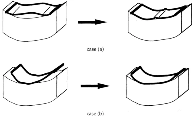
2.5.2 Forming sequence
Controlling the formiing sequence is very important in order to obtain a
i\Veln shape without vriiikles, as can be seen on Figure 2.22. In case (a) if the matcrial hits ti t',ol tirr ,on the edge, the deformation propagates toward the center, generatr ,O a "1rnkie at the center of the part. In case (b) the deformation oriiinates at the center and develops out toward the free edge.
case (a)
case (b)
Figure 2.22: Illustration of the forming sequence for the case of the flange of a
.ORAMLVG LLMITS 49
The torming seiquence is influenced by the geometry .of the machine and the position of the tool iI the machine.
2.5.3
Tool heating
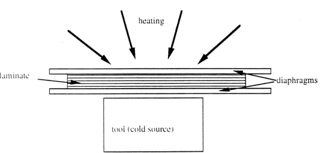
This process related parameter is important especially when the tool is
!eal ancind made .vith a high thermal conductivity material such as aiiluminum. .\ >oi\n on :Fiure 2.23, heating the laminate from the top by
.:o,•\Cct'i!On 1or r.admi• al t :'~ea .uoes not really heat the tool. which mav get
'''armer ater a lon. 'lreeating stage. In the case of an aluminum tool, the
iatter can co•.•ie:rec as a iarge coid source, and therefore, during formingne Wh!etfn the part rt rm the tool the inside plies are cooled even tiought the outsitde lies are
'tlil
heated.heatinge
I I
lamin ate
--dianhragms
Figure 2.23: Illustration of the heating of the laminate.
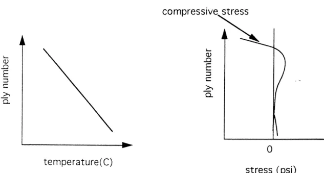
By analog% \with [Tarn and Gutowski]'s work which was a numerical study of the effects of non-isothermal forming on the creation of compressive tress in the laminate. Figure 2.24.a illustrates the temperature distribution
too i (cold source)
---
----
----I _L-__---~---~c~ ~---·b---I F I
50 CHAPTER 2
through the thickness of the laminate and 2.24.b illustrates the corresponding approximated stress distribution through the thickness when the laminate hits a cold tool. Therefore the curves 2.24.b shows compressive stresses which can built up in the core of the laminate making it more likely for wrinkles to appear. The effect is also that the temperature distribution is more even over the part, therefore the average temperature is higher with heating the tool and the outside otf the part, than the configuration where the part is only
heated on the outside.
The effect of heating the tool on the quality of the parts has been confirmed experimentally by the author by forming parts with and without heating the tool. The tendency is that wrinkles are deeper, or more likely to happen wheii the tool is not heated.
CO 4 0 E2 emeaueI temperature(C) stress (psi)
Figure 2.24: (Qualitative illustration of the non-isothermal heating on the stress.inside the laminate.
L
s
FORMING LIMITS 51
2.6
Forming limit diagram
To prevent the loss of many parts because of laminate wrinkling, it is necessarv to have a means to determine the forming limits of the diaphragm •trming -rocess. The forming limit diagram is aimed at representing jrraphicallv the balance between the mechanisms that induce and suppress wrinkling. The primary mechanism that induces wrinkling is the
cInPre1ssive -torc2 L \V. iCi1 builds up in the laminate and the mechanism that
-plpret-s:•- the \vrnnkii:n are related to the tension of the diaphragm.
2.6.1 Mechanisms causing Laminate Wrinkling
We have seen in ,ection 2.3.1 that the wrinkles arise in areas where the shear stresses are too large to be relaxed at a given deformation. And as we have seen in section 2.3.1 there will be a compressive force generated in that region. As we have seen in section 2.4 the compressive force is time and rate dependent and as [Li] has shown, the compressive force in an elemental volume can be approximated by:
Fe Np hint 1 + (2.7) •n+1 t
N,: Number of plies
hI-,,,: Thickness of one ply
FI-,: Evaluation of the interply shear t: Forming time
in,n: rheological factor, evaluated experimentally by the drape test.
52 CHAPTER 2
2.6.2 Mechanism suppressing the wrinkles
[Li] has considered that the main mechanism resisting the laminate wrinkling is the diaphragm tension. The diaphragm tension is given by.the diaphragm thickness D and the nominal stress in the diaphragm:
Td - Dcl
(2.8)
2.6.3
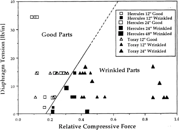
Forming limit diagram
Theretore Laed on the eiuation (2.7) and (2.8) we can draw the following
formilng limit diagramn as Feq versus Td as follows: (Figure 2.25)
The white marks rerepresent the good parts and the black ones, the bad
parts.
Good Parts
A
E A Z[M& A" A
Wrinkled Parts
/
A 0
* U
AA
0.6
Relative Compressive Force
Figure 2.25: Forming limit diagram for C-channels of different sizes
r r5 r ct v · n r E-· r E: F, L r Fu 30 . 20 10 ' O Hercules 12" Good * Hercules 12" Wrinkled O Hercules 24" Good * Hercules 24" Wrinkled * Hercules 48" Wrinkled A Toray 12" Good A Toray 12" Wrinkled A Toray 24" Wrinkled A AL L
Chapter
3
OCEAN ENGINEERING'S
APPLICATIONS
3.1 Introduction
B-Lecause Jiarhragm rorming has the potential to manufacture complex
1a Pl2eCd parts at a rc!at"ci\V tw tooling cost, this processing technique is very
attractive ror marine applications. Among its many advantages, diaphragm forming must allow better fiber placement control than that of other forming methods like matched metal dies, hydroforming, or rubber pad forming. It also requires lower pressures which may enable this technique to make larger parts [Smiley and Schmitt], and because of its simplicity of handling, the machine can readily accommodate various inexpensive tools and many different materials.
Diaphragm forming or vacuum forming can be used as follows:
* assisting the -reforming of the fiber mat for a Resin Transfer Molding (RTNI) process.
* wrming, cho ipd hlass, fiber thermoplastic or glass mat reinforced thermoplastic.
54 CHAP TER 3
* forming big double curved shell-like structures, like boat hulls. This is a challenging task. but diaphragm forming has the potential of forming large parts.
* forming small parts (a few feet long) with carbon fibers.
This chaLoter will briefly discuss the different potential uses of diaphragm forming with respect to its competing process and will focus on the design of
'a part or interest to naval architects and that can be made by diaphragm
iorminir. 1 -ome work hras been done to evaluate how feasible this part would
iDe.
3.2
Different applications related to
diaphragm forming
3.2.1 Assisting RTM (Resin Transfer Molding)
Resin Transfer Molding is a close mold process by which dry fibers are laid into a mold and the resin is then injected into this mold.
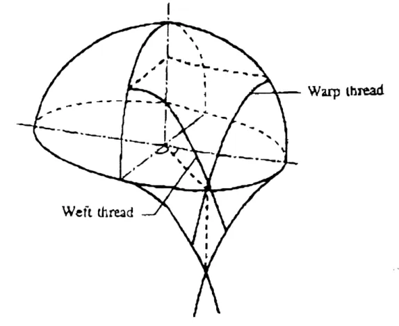
When a large number of double curved shell-like structures are required, fiber preforms have to be formed in order to apply RTM. K. Van Harten [Shenoi aind iWellicome] used a diaphragm forming process where a thermoplastic powder is brushed onto the fiber material, and the material is then formed under vacuum at an elevated temperature and then cooled down so that its shape is stabilized. This technique allows a good fit of the
(OE 'S APPLICATIONS
preform with the mold, avoiding folds or pleats. This is due to the ability of angle variation between the varn system (weft and warp) as seen on Figure
Warp
thread
Figure 3.1: Treilising deformation of woven fabric draped over a sphere.
But the problem of this technique is that because of the trellising behavior
ot the woven fabric, the fibers are no longer evenly spaced and the fiber volume fraction is not constant over the part.
Another variation on this process is the use of the flexible resin transfer molding (FRTIi) process. FRTM is an hybrid combination of diaphragm forming and Resin Transfer Molding (RTM) [Foley]. Separate sheets of dry fibers and solid resin are placed between two elastomeric diaphragms and
56 C'H.A PTER 3
heated so that the resin liquefies. [Foley] The fiber and resin are then compacted bv drawing a vacuum between the diaphragm, and formed to shape by drawing the diaphragm assembly over a hard tool. (See Figure 3.2)
... n ;,. th . ...
Figure 3.2: Illustration of FRTM process flow diagram.
reinforced thermoplastic with the diaphruagm forming process capitalizes on the fact that these materials are very eas and to form that the forming
pressure used in diaphragm forming is uniformly applied over the
diaphragm. Therefore the parts would be smoother and the thickness
variation would be less important than with match die forming or stamping. Because the male or female mold tool can be easy and cheap to manufacture,
()E'S .A PPLICA TIONS 57
3.2.3 Forming whole hulls
in the author , opinion, this technique has not vet been applied, but the
Spotentiai is huLe rr the ,cleasure craft industry. The main characteristic of i1i iiils is that they are usually double-curved shapes with for the most -art smiooth radius ,ariations, although some areas of the hull like the keel or the 11ow can have .-harper edges. In the pleasure craft industry production
u.s f •r unllits ,r , to 12 foot !oniz vessels can be planned. In this range of
-,e
n••
rodct:,on : n. • aphram orming seems to fit well as ana•Jtm
e :aC e irocess. Among thne mnanufacturing tecnniques· 2,ratur•r
nicn can iLe a ultoma•te! tr Processing ship huils we can find:
- the automrated spray-up
- thermnotormin of composites
Tape lay-up requires a high tooling investment in order to develop the manuracturing capabilities, therefore high production volumes are required to redeem the investment. But this option is being studied by some shipyards tor the case of big hulls (>20 m long) , and some telescopic facilities have been developed IRa vime r .
A.utomated spray-up is actuallv the main automated manufacturing process for hulls. !See Figure 3.3) This technique has shown good results and Is less labor intensive than the hand lay-up, therefore also more economical.
5S CHAPTER 3
Figure 3.3: Illustration of automatic spray-up
HIowever, the automated spray-up process has some disadvantages, such
- Emission of styrene, which can be harmful to the operator, and
requires special safety procedures.
- High void content, because air can be entrapped during the spray-up. Therefore this technique, if not applied with care, will result in a laminate with generally a lower quality than that obtain by hand
lay-up.
- lack of ulniversalit in the use of material. The spray-up techniques
require the use of short fibers which have slightly lower mechanical properties than long fibers. Thus requiring, in some case, the use of a manuLal hand lay-up of prepreg or continuous fibers, if higher structural properties are needed.
OE'S APPLICATIONS 59 In some special cases specific sandwich design requires the lay-up of different materials such as continuous fibers, foam core, or thermoplastic sheets. Therefore a good technique should be flexible enough to accommodate different kinds of materials.
MLoreoer, .i, the perspective of increasing governmental regulation of as t miIssion S >riginating from gel-coat fiber reinforced polyester mann uacturingI vprocesses, ,new closed molding techniques are being iL\estigated bL boat manufacturers. The work of [Young] focuses on the ntiermororming or thermoplastic composite hulls and decks for the market of meters long boats with production runs exceeding 250 units a year..And 'Youngj points out that the thermoforming technique (such as matched die molding) has the potential of dividing by five the manhours to produce the hull andci deck for these boats, from 25 - 40 hours for conventional FRP manufacturing technique to 5 - 7 hours with a thermoforming process.
From these perspectives, diaphragm forming has some advantages over automated spray-up because the technique is more flexible and can handle different types of materials. Moreover, it is a less hazardous technique which allows a better control of toxic fumes. Diaphragm forming has the potential to 'yield better results than matched die molding at a significantly lower tooling cost.
Howev\er, before this technique can be applied, the size scaling effects must be understood and fully prospected [Li]. This can be overcome by "Reinforced Diaphragm Forming" as developed in the chapter 4.
.Another problem related to the use of double diaphragm forming is the presence of an inner diaphragm which does not allow a good control of the
) 'HA PTER 3
inner dimension of the part. This is due to the fact that while stretching, the thickness of the diaphragm can vary a lot. This variation may not be crucial for a hull, but the inner diaphragm can be eliminated by using a thin disposable diaphragm, or by using the "Inflated Tool Forming" developed by the M.I.T composite forming group.(see Figure 3.4 for a brief description of Inflated Tool Forming").
Top Plate lop Diaphragm
4"- in.m I
Figure 3.4: Inflated Tool Forming
3.2.4 Forming advanced composite for marine applications
Many Ocean Engineering applications require the use of high strength and high stiffness composites which are not subject to static fatigue. For applications like submarines, high speed boats where weight is an important issue, the use of carbon fibers is increasing. Many small size parts made out of carbon fibers are then required, the study will now focus on the feasibility of man utfactuLrinig a part which would realize the intersection of two orthogonal stiffeners.
/ /
(II)
-• III 't1
I
OE'S .4 PPLICA TIONS
3.3
Design and proof of concept
3.3.1 Design of the part
When building a stiffened single skin vessel, the intersection of two 1rthogonal sets orf stiffeners !Longitudinal and Transversal) is a critical aspect
in, the design ot a nip ? huil. Stiffener intersections are difficuit to fabricate,
ca \V, and prýod•ce -trei.- concentrations. For marine applications, the design
or composite ,i;tfeners i- rererred to as "top hat" -hape, as shown in figure 3.5.
TABLE CONTAINING UNIDIRECTIONAL REINFORCEMIENT NON-STRUCTURAL FOAM FOPRME COMPLIANT RESIN / I WEB i FILLET /
K
SHELL PLATIN-;Figure 3.5: ingle skin hull typical stiffener top hat shape
Figure 3.h ,hov\s a cross section of the structural arrangement of a transversely framed single skin hull
FLANGE
d
iI I
I
6(2 C(•LPTER 3
Figure 3.6: Transversely framed single skin hull
Figure 3.7 shows a typical stiffened plate with transverse and longitudinal stiffeners intersecting each other in many places.
Figure 3.8 shows the structural arrangement of the Sandown Class ininehunter with a longitudinally stiffened bottom to avoid, as much as possible, stiffener intersections, although, as we can see on fig 3.7, it is not alw'avs possib le.
OE'S APPLICATIONS 63
Figure 3.7: Stiffened plate with transverse and longitudinal stiffeners.
(04 CHAPTER 3
The idea underlvinig this work is to design a unique cross-shaped part W\\hich would more easily accommodate the intersection of stiffeners. The part has the ,-hape shiown in FiKure 3.9. In Figure 3.9, the two intersecting
:tiffeners have the same dimensions, but this is not a requirement.
Figure 3.9: Illustration of a Top-hat shape intersection cross with sharp corners
This part is not easy to hand lay up because of its many different curvatures. This part presents interesting problems for diaphragm forming because it has a reverse curvature which has not been investigated before. In order to improve the cost effectiveness of this process this part should be standardized, so that one tool can process many intersections. In order to do
,)ES ) APPLICATIONS 65
so, the number of different stiffeners sections reauire to reinforced a hull should be minimized. If this is not possible, a composite part which would make a transition between a stiffener and an intersection with different dimensions can be designed as in Figure 3.10. Trying to standardize the part difficult to manufacture is an important task in order to track down the cost. If this t'ype of part could be standardize, its cost could be sharply cut down by
using the diaphragm rorming process.
cross part
-.tiiiener \.
-~.~~ -~ .~~:~.~
Core
Figure 3.10: Joining part for different stiffeners sizes.
3.3.2 Experimental approach
The process of manufacturing this part starts by the realization of a tool, in our case, the easiest and cheapest way was to build a male wooden tool with some fillers for the fillet. The dimensions of the tool are shown in figure
3.11.
... ...
...
66 CHAPTER 3
Figure 3.11: Top view and front view of the top-hat shape intersection part.
OE'S APPLICATIONS 67
Figure 3.12: Illustration of the set up of the forming machine.
The first -et or e\periments was aimed at understanding where the wrinkles were the most likely to occur. In order to do so, two sets of four plies or AS4/ 35)1-h( Hercules woven material with different ply orientations have been tested at room temperature and with a high forming rate on the order of two minutes. As seen in chapter 2 these conditions are drastic because at room temperature the inter-ply shear stresses are very high and with a high forming rate the shear stress have only little time to be relaxed.
Experiment 1.a: