HAL Id: hal-03020521
https://hal-univ-pau.archives-ouvertes.fr/hal-03020521
Submitted on 23 Nov 2020
HAL is a multi-disciplinary open access
archive for the deposit and dissemination of
sci-entific research documents, whether they are
pub-lished or not. The documents may come from
teaching and research institutions in France or
abroad, or from public or private research centers.
L’archive ouverte pluridisciplinaire HAL, est
destinée au dépôt et à la diffusion de documents
scientifiques de niveau recherche, publiés ou non,
émanant des établissements d’enseignement et de
recherche français ou étrangers, des laboratoires
publics ou privés.
A Tesla Transformer and a Coaxial Peaking Switch as a
UWB Pulse Source
Y Amal, Laurent Pecastaing, Marc Rivaletto, Thierry Reess, P Pignolet, B
Cassany, Antoine Silvestre de Ferron, L Courtois, E Merle
To cite this version:
Y Amal, Laurent Pecastaing, Marc Rivaletto, Thierry Reess, P Pignolet, et al.. A Tesla Transformer
and a Coaxial Peaking Switch as a UWB Pulse Source. Acta Physica Polonica A, Polish Academy of
Sciences. Institute of Physics, 2008. �hal-03020521�
HAL Id: hal-03020521
https://hal-univ-pau.archives-ouvertes.fr/hal-03020521
Submitted on 23 Nov 2020
HAL is a multi-disciplinary open access
archive for the deposit and dissemination of
sci-entific research documents, whether they are
pub-lished or not. The documents may come from
teaching and research institutions in France or
abroad, or from public or private research centers.
L’archive ouverte pluridisciplinaire HAL, est
destinée au dépôt et à la diffusion de documents
scientifiques de niveau recherche, publiés ou non,
émanant des établissements d’enseignement et de
recherche français ou étrangers, des laboratoires
publics ou privés.
A Tesla Transformer and a Coaxial Peaking Switch as a
UWB Pulse Source
Y Amal, L Pecastaing, M Rivaletto, T Reess, P Pignolet, B Cassany, Antoine
Silvestre de Ferron, L Courtois, E Merle
To cite this version:
Y Amal, L Pecastaing, M Rivaletto, T Reess, P Pignolet, et al.. A Tesla Transformer and a Coaxial
Peaking Switch as a UWB Pulse Source. Acta Physica Polonica A, Polish Academy of Sciences.
Institute of Physics, 2008. hal-03020521
Vol. 115 (2009) ACTA PHYSICA POLONICA A No. 6
Proceedings of the 2nd Euro-Asian Pulsed Power Conference, Vilnius, Lithuania, September 22–26, 2008
A Tesla Transformer and a Coaxial Peaking Switch
as a UWB Pulse Source
Y. Amal
a, L. Pecastaing
a,∗, M. Rivaletto
a, T. Reess
a, P. Pignolet
a, B. Cassany
b,
A. Silvestre de Ferron
b, L. Courtois
band E. Merle
ba
Laboratoire de G´enie Electrique, Universit´e de Pau, 2 av. Angot, 64053 Pau, France
b
CEA CESTA, BP 2, Routes des Gargails, 33114 Le Barp, France
This paper presents a high voltage pulse source which is able to generate ultra wideband (UWB) pulses during about 1 ns through a 16 antennas array. This UWB source is composed of a 50 kV DC voltage supply, a Tesla transformer to amplify this voltage up to 400 kV, a gaseous pressurized peaking switch and an impedance transformer (50 Ω → 3.125 Ω). This output impedance value corresponds to the input impedance value of a sixteen 50 Ω antennas array. That is why a distributor is needed in order to feed the antenna array. In this paper, the peaking switch and the capacitive line divider used to characterise the generated pulses are particularly described. The peaking switch is based on the principle of a line discharge by means of a high pressure gas switch. It is loaded with a Tesla transformer to obtain a good pulse reproducibility. The main characteristics of the output pulse waveform (amplitude and rise time) are linked to the properties of the gas switch and particularly to the gap distance, the pressure and the nature of the gas used in the switch filling. The aim is to find a good compromise between various parameters as the output pulse amplitude, the rise time and the repetition rate in order to ensure a better efficiency of the UWB source. Classical voltage measurement techniques do not allow us an estimation of the main characteristics of such an output signal. Therefore a voltage probe was designed and realised to measure both the amplitude and the rise time of the pulses delivered by the generator. This device is based on the principle of a capacitive line divider. Calibration tests (transient and frequency tests) were performed and show that the high cut-off frequency, around 2.5 GHz, is consistent with the tran-sient response of the output high voltage waveform. The design, realisation and calibration tests are also presented.
PACS numbers: 84.70.+p, 07.57.Hm, 84.30.Ng
1. Introduction
The interest for high voltage closing switches on nanosecond time scales has risen in a range of applica-tions including high power microwave, pulse laser or par-ticle accelerators. Recent works have extended the fea-sibility of a broadband device for high electromagnetic field radiations. This kind of device consists of a high gain antenna driven by a self-contained, compact, repet-itive and voltage adjustable generator. In this context, a prototype of a compact generator was developed. Its main characteristics are an output voltage in the range of 100–300 kV, not more than a few hundreds of picosec-onds rise time and a repetition rate of a few tens Hz.
2. UWB pulse source description
This UWB pulse source aims at generating impulses of a few hundreds kV with fast rise times from a DC continuous voltage of 50 kV. This source consists of the devices presented in Fig. 1:
• a 50 kV DC voltage supply,
∗corresponding author; e-mail: [email protected]
Fig. 1. Design of the UWB pulse source.
• a Tesla transformer to amplify this voltage and its driving system,
• a gaseous pressurized peaking switch, • a capacitive line divider,
• an impedance transformer (50 Ω → 3.125 Ω), • a distributor towards a sixteen 50 Ω antennas array.
1116 Y. Amal et al.
2.1. Design of the coaxial generator with its peaking stage
The purpose of this component is to sharpen the rise time of the impulse generated by the air Tesla trans-former in order to reach rise times close to 200 ps [1, 2]. It consists of a spark-gap with pressurized gas but with-out air flow and a pressure being able to go up to 100 bars. The aim is to place this peaking switch on the curve of Paschen [3] where the conditions of the product P (pres-sure) × d (gap distance) make it possible to reach break-down voltage values of the peaking switch near the max-imum of the output pulse generated by the air Tesla transformer. The gap distance can be adjusted from 0 to 5 mm. The impedance of the input forming line is 30 Ω, whereas the output transmission line impedance is 50 Ω to improve the pulse voltage amplitude available on the load.
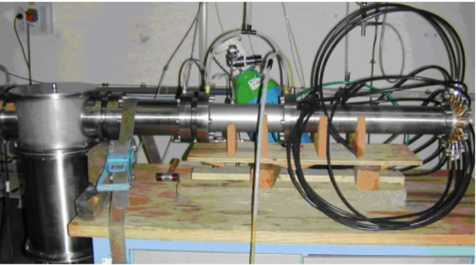
2.2. Design of the capacitive line divider
The output voltage measurement is achieved by probes made of a capacitive line divider [3] associated with at-tenuators.
A complete calibration (transient and frequency re-sponses) test was performed on the divider used in this experiment. The transient response to an ultra short pulse is very important. Our vector network analyser (VNA Anritsu MS4623B) makes it possible to simulate the transient response of an impulse close to a Gaussian pulse. The VNA simulates pulses with a rise time of 97 ps and duration at half width of 180 ps. The refer-ence pulse measurement and the measure with capaci-tive divider give very close characteristics: the rise time (10% to 90%) is now 104 ps and the width at half max-imum is 205 ps. However this time-domain calibration is not sufficient to determine the characteristics of this probe accurately. A frequency calibration is also needed to complete this first result.
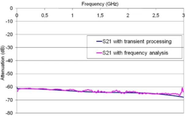
The VNA measures the frequency response of the probes to complete the first calibration test. The trans-mission and reflection parameters were studied up to 3 GHz. The transmission parameter obtained is linear and constant in regard to the frequency. The transmis-sion coefficient of the probe used in our experiments is about −62 dB up to 3 GHz. The measurement of this parameter is presented in Fig. 2. It is compared with the results issued from the transient analysis. Besides, the reflection parameter is always lower than −14 dB.
The main characteristics of the divider for our appli-cation are an upper bandwidth of 2.9 GHz and an atten-uation of −62 dB. It enables pulse measurement with a rise time as short as 130 ps. This value is shorter than the fastest rise time measured in this study.
2.3. Design of the impedance transformer The purpose of this element is to gradually transform the characteristic impedance [5]. In our case, the aim consists of passing from an input impedance of 50 Ω to
Fig. 2. Comparison between the transmission coef-ficient and the results obtained from the transient analysis.
an output impedance of 3.125 Ω, corresponding to the impedance presented by 16 cables in parallel connected to a 16 antennas array.
3. Experimental results
Figure 3 shows the typical waveform of the charging voltage of the peaking stage driven by the transformer. The combination of the Tesla transformer and the peak-ing stage delivers a monopolar impulse. For a better efficiency, the breakdown of the peaking spark gap must occur during the second alternation. Whereas this condi-tion can be assured with a low pulse repeticondi-tion frequency (PRF), it becomes more delicate when the PRF is in-creased up to 200 Hz.
Fig. 3. Typical waveform of the transformer output voltage to drive the peaking switch.
Fig. 4. Typical waveform after the peaking switch (rise time = 250 ps, VOUT= 240 kV).
A typical output pulse is presented in Fig. 4. The rise time is approximately 250 ps and the pulse width at
A Tesla Transformer and a Coaxial Peaking Switch as a UWB Pulse Source 1117 half maximum of 2.5 ns. The pulse amplitude is close
to 250 kV.
4. Conclusions
Our ultra wideband pulse source combines a Tesla transformer and a monopolar peaking stage based on a pressurised gaseous switch. The tests are carried out very satisfactorily to obtain an output voltage in the range of 100–300 kV, not more than 250 ps of rise time and a repetition rate of a few tens Hz. However, to take into account a criterion of reliability, the pulse source will have to undergo complementary experiments for a tech-nological validation.
References
[1] G.A. Dawson, D.E. Davies, Research Notes, Brit. J. Appl. Phys. 14, 155 (1963).
[2] E.E. Kunhardt, W.W. Byszewski, Phys. Rev. A 21, 2069 (1980).
[3] L. P´ecastaing, J. Paillol, T. Reess, A. Gibert, P. Domens, IEEE Trans. Plasma Sci. 34, 1822 (2006).
[4] L. P´ecastaing, J. Paillol, T. Reess, A. Gibert, P. Domens, Measurement Sci. Techn. 12, 1718 (2001).
[5] V.I. Koshelev, V.P. Gubanov, A.M. Efremov, S.D. Korovin, B.M. Kovalshuk, V.V. Plisko, A.S. Stepchenko, K.N. Sukhushin, Proc. 2nd Intern. Congress on Radiation Physics, High Current Elec-tronics and Modification of Materials, Tomsk, 258 (2006). Powered by TCPDF (www.tcpdf.org) Powered by TCPDF (www.tcpdf.org) Powered by TCPDF (www.tcpdf.org) Powered by TCPDF (www.tcpdf.org) Powered by TCPDF (www.tcpdf.org) Powered by TCPDF (www.tcpdf.org)