Publisher’s version / Version de l'éditeur:
Vous avez des questions? Nous pouvons vous aider. Pour communiquer directement avec un auteur, consultez la
première page de la revue dans laquelle son article a été publié afin de trouver ses coordonnées. Si vous n’arrivez pas à les repérer, communiquez avec nous à PublicationsArchive-ArchivesPublications@nrc-cnrc.gc.ca.
Questions? Contact the NRC Publications Archive team at
PublicationsArchive-ArchivesPublications@nrc-cnrc.gc.ca. If you wish to email the authors directly, please see the first page of the publication for their contact information.
https://publications-cnrc.canada.ca/fra/droits
L’accès à ce site Web et l’utilisation de son contenu sont assujettis aux conditions présentées dans le site LISEZ CES CONDITIONS ATTENTIVEMENT AVANT D’UTILISER CE SITE WEB.
Proceeding of the Additive Manufacturing with Powder Metallurgy Conference
2019, 2019-06
READ THESE TERMS AND CONDITIONS CAREFULLY BEFORE USING THIS WEBSITE.
https://nrc-publications.canada.ca/eng/copyright
NRC Publications Archive Record / Notice des Archives des publications du CNRC :
https://nrc-publications.canada.ca/eng/view/object/?id=e9075897-9a1c-4eb3-a46d-73ba79055b1d https://publications-cnrc.canada.ca/fra/voir/objet/?id=e9075897-9a1c-4eb3-a46d-73ba79055b1d
NRC Publications Archive
Archives des publications du CNRC
This publication could be one of several versions: author’s original, accepted manuscript or the publisher’s version. / La version de cette publication peut être l’une des suivantes : la version prépublication de l’auteur, la version acceptée du manuscrit ou la version de l’éditeur.
Access and use of this website and the material on it are subject to the Terms and Conditions set forth at
Additive manufacturing of soft and hard magnetics materials used in
electrical machines
Bernier, Fabrice; Ibrahim, Maged; Mihai, Mihaela; Thomas, Yannig; Lamarre,
Jean-Michel
Additive Manufacturing of Soft and Hard Magnetic Materials Used in
Electrical Machines
Fabrice Bernier, Maged Ibrahim, Mihaela Mihai, Yannig Thomas and Jean-Michel Lamarre
National Research Council Canada Boucherville, Qc, J4B 6Y4, Canada
ABSTRACT
Additive manufacturing (AM) techniques such as cold spray and fused filament fabrication allows for 3D build-up permitting fabrication of high complexity shapes and configurations. The fabrication of soft and hard magnetic materials using these techniques was investigated in the context of 3D electrical machines. The use of 3D finite element analysis (FEA) to develop new motor topologies based on the advantages offered by AM will be discussed. FEA was also used to orientate the material development by identifying the most critical properties. The hard magnetic properties (coercivity and remanence), soft magnetic properties (permeability and losses) of both types of materials fabricated by both AM processes will be presented.
INTRODUCTION
Additive manufacturing (AM) of metal parts was successfully used in various applications for the fabrication of complex shape mechanical parts. As AM techniques and processes are maturing, a new focus in research and development is devoted to functional materials where various physical properties of the materials need to be optimized for their utilization. Magnetic materials are one type of functional materials that has generated interest lately in the AM community. In the last five years, research and development efforts for the development of conventional magnets has been steadily increasing. The main motivation for this work is the potential benefits arising from the agility of AM processes both for the prototyping stage and for the realization of complex designs. Ultimately, additive manufacturing could offer significant advantages for the low volume production of customized parts while increasing the design flexibility for magnetic components in electrical machines.1
In most electrical machines applications, hard magnetic materials are used in combination with soft magnetic materials. When compared to AM of mechanical components, AM of magnetic materials presents additional difficulties and challenges. One of the most important challenges is probably that the high energy used tends to negatively affect the physical properties of the materials. For NdFeB, oxidation and phase transformation can adversely affect the performance of the magnet.2-3In the case of soft
magnetic materials, the difficulty to incorporate insulation between powder particles in an AM process limits their utilization when low eddy-current losses are required.4In order to address these shortcomings,
the research presented in this paper was focused on low-energy, solid-state AM processes that can offer the flexibility and design advantages of AM without modifying the functional properties of the soft and hard magnetic materials.
Another challenge often encountered in the development of new additive manufacturing processes and parts is the availability of high quality feedstock. In the case of the highest energy density magnets (i.e. NdFeB),5commercial powders are readily available since powder metallurgy (compaction, sintering and
injection molding) is the traditional manufacturing route. Soft magnetic materials (such as electrical steel) are usually produced using a cold rolled strip process. Some high performance materials, such as high silicon FeSi and FeCo, are brittle and difficult to manufactured using rolling process. Powder injection
molding has also been developed for those soft magnetic materials.6Also, soft magnetic composites in the
form of individually insulated pure iron particles are produced by powder compaction and has seen some usage in electrical machines7-8and could be used in AM processes.
Some solid-state processes for AM of metallic powders require the use of a polymeric binder to act as a powder carrier and/or to give structural properties to the component. Li et al. used extrusion of pellets of NdFeB and nylon9while Huber et al. extruded a filament composed of nylon and NdFeB and then used
fused filament fabrication (FFF) to build magnets layer by layer.10Khatri et al. used FFF using a soft
magnetic compound formed of ABS polymer and 17-4PH stainless steel as the functional material.11
Alternatively to the use of a polymer binder, King et al. have shown that an Al binder/NdFeB composite can be successfully fabricated using the cold spray process.12This process was also described in our
previous work.13-14We have also shown that pure Fe can be applied using a binderless cold spray
approach for the fabrication of soft magnetic materials. Generally, the requirement for a binder matrix limits the overall performance of the materials when compared to the traditional routes. Hence, for those material to be used in electrical machine applications, a good understanding of the impact of their properties on the magnetic flux and overall machine performance is required and new topologies must be designed.
As AM of magnetic components opens up the flexibility in designing more complex electrical machines, new innovative topologies start to emerge in the literature. Huang et al. and Tseng et al. used AM of soft magnetic composites to develop hollow and honeycomb structures, respectively.15-16In another study,
Krishnasamy et al. developed a 3D flux focusing hybrid-field design.17When developing a new electrical
machine configuration, finite element modelling is used to evaluate the machine performance and reduce the prototyping cost. To accurately evaluate the motor performance by FEA, the complete material properties must be known.
In this study, the magnetic performance of soft and hard magnetic AM components will be discussed for both the FFF and the cold spray processes. The selection and influence of the magnetic powders
characteristics on both processes will be covered. The type of powders, their morphologies and particle size distributions will be discussed in respect to AM feasibility. The required process parameters to achieve high performance AM parts using commercially available equipment, powders and thermoplastic polymers will be covered. Finally, new designs exploiting the advantages of AM processes and
circumventing the inherited magnetic properties will also be explored.
MATERIALS AND EXPERIMENTAL PROCEDURES
Powders
The different hard and soft magnetic powders that were used in this study are listed in Table I. The table details the main characteristics of the powders and for which AM process they have been used. The densities of the powders were measured using gas pycnometry and their particle size distributions was obtained by laser diffraction using a Beckman Coulter LS13 320 apparatus.
Table I: Description of powder feedstocks used in this study Type Powder
commercial name
Producer Composition Density
(g/cc) Size D 50
(µm) AM Process
Hard Magnetic
MQP-S-11-9 Magnequench NdFeB 7.40 40 CS and FFF
MQFP-B Magnequench NdFeB 7.45 10 CS
Soft
Magnetic FeSi Sandvik-Osprey Fe3.8Si 7.42 23 CS and FFF 195SP Rio Tinto Metal
Powders Fe 7.82 36 CS Metallic Binder H15 Valimet Al 2.70 20 CS H3 Valimet Al 2.70 4 CS
Figure 1 shows a micrograph of the four different magnetic powders that were used. For the FFF process, spherical powders (fig. 1 a) and c)) with a D50in volume between 20- and 40 µm were used to ensure
good flowability. Also, crushed NdFeB powder was avoided as sharp edges could damage (fig. 1 b)) the extruder and 3D-printer. For the cold spray process, the crushed powder was also studied since it offers better magnetic properties than the atomized spherical powder. Two different sizes of aluminium powder were used to study the effect of the binder size on the overall magnetic loading achievable. Finally, pure iron and FeSi were also evaluated as soft magnetic materials in the CS process.
Figure 1. Micrographs of the magnetic powders used: a) MQPS-11-9 (NdFeB) b) MQFP-B (NdFeB) c)
Fe3.8Si d) 195 sp (pure Fe). Cold Spray Process
The cold spray trials were performed using a Plasma Giken (Yoriimachi, Japan) PCS 800 gun. Operating gun pressure was varied from 3 to 4.9 MPa and gas temperature was set between 600 and 1000°C. Spray distance was kept at 80 mm. The gun displacement speed was set at 100 mm/s. When a mixture of different powders was used, powders were pre-mixed before being sprayed.
Fused Filament Fabrication
For the FFF process, the thermoplastic polymer was a polyamide 6 (PA6, more broadly known as nylon), Ultramid B27 E 01 grade from BASF. Composite pellets with various volume fraction of metallic powders were compounded using a Bühler clam shell 20 mm extrusion line. To validate the properties of the compound, the pellets were compression molded using a Wabash press into 4 mm thick plaques. The plaques were then cut to the different specimen dimensions requirements as per the used ASTM standard. The mechanical properties were measured to evaluate the performance of the composites obtained by extrusion and compression molding (usual processes for thermoplastics) but also to determine the
feasibility of using those compounds to build sufficiently flexible filaments for FFF. The flexural strength and modulus were evaluated according to the ASTM D790 standard. The compound showing the best compromise between high magnetic performance and processability was reprocessed through the extrusion line by adding 10 vol% of polymeric additive to obtain a high quality filament of 1.75 mm in diameter. Finally coupons were 3D-printed using a Prusa i3 MK3S printer.
Magnetic Characterization
The hysteresis curves for both the hard and soft magnetic material were obtained using a Hysteresigraph Permagraph L equipment from Magnet Physik (Fishers, Indiana, USA) on a 25.4 mm diameter disk with a 4 mm thickness. The sample weight and volume were evaluated for density measurements. Figure 2 schematically presents the different properties that where obtained from the hysteresis curves. The performance of hard magnetic materials (fig. 2 a)) can be characterized in terms of their magnetic remanence (Br), intrinsic coercivity (Hci) and energy product ((BH)max). For the soft magnetic material
(fig. 2 b)), the saturation occurs at Jmax, for a magnetic field of about 500 kA/m. Bmaxat 500 kA/m is also
reported. Finally, the permeability (μ) can be derived as the initial slope of the magnetization curve. In the present case, the slope up to a field of 0.5 T was used. For the cold sprayed soft magnetic composites, DC and AC magnetic characterization was done on a KJS associates hysteresis graph (model ACT-500, SMT-500, 7385K Fluxmeter), according to ASTM standard A 773 to obtain the magnetic losses as a function of frequency. The characterization was done on toroids with an outside diameter of 53.6 mm, an inside diameter of 40.6 mm and a height of 6.25 mm.
Figure 2. Typical hysteresis curves obtained during the magnetic measurements and their reported
values for a) Hard magnetic materials and b) Soft magnetic materials.
Finite Element Analysis Modeling
The motor electromagnetic performance was simulated using the JMAG finite element analysis (FEA) software. The magnet eddy current losses were also evaluated using 3D FEA.
RESULTS AND DISCUSSION
Cold Spray of NdFeB
This section main focus is on the selection of the magnetic and binder powders to achieve the highest loading of magnetic material in the composite component built by cold spray. A more detailed description of the process and process parameters can be found in previous papers.13-14The composition of the
powder mixes, the characteristics of the built coupons and the magnetic properties are reported in Table II. First, it is important to notice that when a mixture of a high hardness powder (ex.: NdFeB) and a low hardness powder (ex.: Al) are sprayed, the final composition of the built may not correspond to the initial mix composition. The softer material will preferentially deposit and its volume fraction will be higher in the built parts than in the initial mix. The volume fraction (Vf) of hard magnetic material was determined
by calculating it from the coupon density and from the density of the powders (reported in Table 1). The amount of porosity was considered negligible. This assumption is generally reasonable in light of the obtained micrographs (see Figure 3).
0 0.1 0.2 0.3 0.4 0.5 0.6 -800 -600 -400 -200 0 M ag ne tiz at io n J, T
Magnetic field strength H, kA/m Remanence (Br) Co er ci vi ty (Hci ) -2.5 -2 -1.5 -1 -0.5 0 0.5 1 1.5 2 2.5 -1000 -500 0 500 1000 M ag ne tiz at io n, J an d In du ct io n, B (T )
Magnetic Field Strength, H (kA/m)
J
B Bmax
Jmax
Table II. Spray conditions and performance of hard magnetic composite built by cold spray Powder mix composition Coupons characteristic Magnetic properties NdFeB (vol.%) Al binder
(vol.%) ρ (g/cm3) Calculated Vf(%) Br(T) (BH)max (kJ/m3) (kA/m)Hci 52% MQP-S-11-9 48% H15 4.43 36.9% 0.26 12 676 52% MQFP-B 48% H15 4.32 34.0% 0.28 13 715 77% MQFP-B 23% H15 5.05 49.5% 0.38 23 706 77% MQFP-B 23% H3 6.15 72.6% 0.50 36 693 38.5% MQP-S-11-38.5% MQPF-B 23% H15 5.01 48.9% 0.38 22 694
Figure 3 compares the micrograph of coupons prepared using the spherical MQP-S-11-9 and angular MQFP-B powders using 52%-48% mixes. It can be observed that when using larger spherical particles (fig. 3 a)), the impact between two NdFeB particles tends to shatter the particles potentially creating small voids that could reduce magnetic performance. The measured magnetic content is 3% higher for the spherical powder, probably due to the higher packing factor for the spherical powder than that for the crushed. Indeed, the tap density was 4.7 g/cm3vs 3.7 g/cm3for the MQPS-11-9 and the MQFP-B,
respectively. That being said, the lower intrinsic magnetic properties of the MQPS-11-9 powder (Br=
0.745 T from manufacturer datasheet) compared to the MQFP-B powder (Br= 0.880 T) led to lower
overall performance of the coupons even if the volume fraction was higher.
Figure 3. SEM micrograph of CS coupons made with a pre-mix of a) 52% of MQPS-11-9 with 48% of
H15 aluminum binder and b) 52% MQFP-B with 48% of H15 (NdFeB particles in light grey and the Al in dark grey)
To increase the magnetic content in the CS coupons, three strategies were evaluated and compared. First, the amount of binder was decrease from 48% to 23% with the MQFP-B powder (fig 4 a)). Secondly, the particle size distribution of the aluminum binder powder was significantly reduced (fig. 4 b)). The
parameters used for the deposition of these two materials were discussed in our previous work.13-14Lastly,
to increase the packing factor while trying to benefit from the higher performance of a crushed powder, a mix of the large magnetic powder with the small magnetic powder was evaluated (fig. 4 c)). The first and last strategies achieved similar results. In terms of Brperformance, an increase of 38% was achieved
compared with the premix containing 48% of aluminum. No clear advantage was obtained by using two magnetic powder particle size distributions. On the other hand, a significant increase in the volume fraction of the magnetic phase was obtained when the particle size of the binder was reduced to 4 microns. Indeed, this allows reducing the amount of binder holding the magnetic phases together. It is
with that strategy that the highest performance was achieved; Brwas increased by nearly 30% and
(BH)maxby 56% when compared with similar premix Al composition.
Figure 4. Micrograph of CS coupons made with a pre-mix of a) 77% of MQFP-B with 23% of H15 b)
77% MQFP-B with 23% of H3, c) 38.5% of MQP-S-11-9 – 38.5% of MQFP-B with 23% H15.
Cold Spray of Soft Magnetic Material
Contrarily to NdFeB, which is too hard to be deposited in cold spray without the addition of a binder, soft magnetic materials such as pure iron can be deposited with that technology without any binder. However, soft magnetic composites used for the compaction process possess a particle size distribution (≥100 µm), well above the size that are usually suitable for cold spray (˂ 50 µm). Hence, commercially available SMC powders could not be used as is.
Table III, summarize the materials tested and the results obtained and compares it with data available for compacted SMC (from Hogänas datasheet). The first trials were performed with pure iron possessing a D50of 30 µm. The obtained density was higher than compacted SMC due to the absence of lubricant in
the cold spray process and due to the very high deformation of the particles upon impact. As expected from the density and since pure iron is used in both cases, the DC magnetic results were similar. However, under AC testing, the losses for the cold spray produced SMC were significantly higher than that for SMC obtained using the standard production route. This is mainly due to the absence of electrical insulation surrounding each particle. The metallurgical bonding and the absence of electrical insulation contributed to obtain a higher electrical conductivity and hence high eddy current losses when exposed to AC magnetic field. To increase the resistivity of the sprayed components, FeSi powder was used, as this alloy possess a higher resistivity than pure Fe. Initial trials revealed that the deposition of FeSi is
challenging due to its higher hardness and thus lower deformation level. In order to alleviate this problem, two different pre-mix compositions of Fe and FeSi were used (49%-51% and 24%-76%). The losses at higher frequencies, a region where the eddy current losses become more dominant compared to the hysteresis losses, were effectively reduced by half when the highest volume fraction of FeSi was used, but still remained significantly higher than for compacted SMC. At high FeSi content, it was also observed that the permeability was lower and the coercivity (Hc) was higher suggesting a high content of defects
(grain boundary and strain hardening). To reduce the effect of defects on the DC performance, a heat treatment at 480°C for 20 min was performed on the sample. The treatment was effective to increase the permeability by 44% and reduce the coercivity by 22%, the latter indicates a reduction of the hysteresis losses. However the heat treatment also increased the eddy current losses leading to an increase of the total losses of 10% at 60 Hz and 18% at 400 Hz. The current level of performance of cold spray SMC would restrict their use to low frequency applications if the resistivity is not increase to control high frequency losses.
Table III. Spray conditions and performance of soft magnetic composite built by cold spray Powder mix ρ (g/cm3) µ B12000 (T) (A/m)Hc Losses at 1 T (W/kg)60 Hz 400 Hz Fe 7.63 480 1.49 697 33 836 49%Fe – 51% FeSi 7.65 500 1.78 646 27 528 24% Fe- 76% FeSi 7.4 360 1.61 828 26 409 24% Fe – 76%FeSi (HT) 7.4 520 1.64 643 28 484
Somaloy 700 1P 7.45 540 1.56 (at B10000) N/A 10 (at 100 Hz) 46
Fused Filament Fabrication
In this section, fused filament fabrication of both hard and soft magnetic composites will be discussed. Both materials will be discussed simultaneously since the process and conditions are similar for both material. As a first step, an extrusion process is used to obtain dense pellets with the desired composition. To measure the magnetic and mechanical performance of the extruded compound, compression moulding was used to build coupons. Table IV summarizes the measured density and porosity of the coupons for the different mix compositions. Contrarily to cold spray, the composition of the feedstock material is preserved in the final composition. For both types of magnetic materials, the porosity increase drastically when only 30 vol.% percent of PA6 binder is used. This is directly linked to the maximum compactness of the hard material, i.e., there is not enough binder to fill the inter particles space.
Table IV. Compositions and characteristics of hard and soft magnetic materials built by extrusion and
compression moulding
Type Composition Theoretical density (g/cm3)
Measured density (g/cm3)
Porosity (%) Magnetic (vol.%) Binder (vol.%)
Hard 30% MQP-S-11-9 70% PA6 2.99 2.98 0.2 50% MQP-S-11-9 50% PA6 4.26 4.18 1.8 70% MQP-S-11-9 30% PA6 5.53 4.79 13.3 Soft 30% Fe3.8Si 70% PA6 3.04 2.91 3.4 50% Fe3.8Si 50% PA6 4.35 4.13 3.8 70% Fe3.8Si 30% PA6 5.65 4.80 14.0
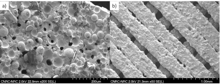
Figure 5 shows the morphology observed in Scanning Electron Microscopy (SEM) of the fracture surface of compression molded coupons. A close examination allows to identify the distribution of the powder particles inside the compression moulded composites. It can be observed that little or no adhesion occurs between the two phases and that at 30% of PA6, some binding material is lacking between particles.
Figure 5. Fractography of hard and soft magnetic materials built by extrusion and compression moulding
a) 70% PA6 – 30% NdFeB, b) 50% PA6 – 50% NdFeB c) 30% PA6 – 70% NdFeB d) 70% PA6 – 30% FeSi e) 50% PA6 – 50% FeSi f) 30% PA6 – 70% FeSi.
The mechanical tests results for different PA6 concentrations can be found in Figure 6. The flexural strength at rupture (fig. 6 a)) is equal or slightly higher than for pristine PA6. This result is surprising as Figure 5 reveals that the composite material shows some porosity and potentially lack of cohesion at the interface. Another important aspect is that the flexural modulus of the composite material was highly increased. This parameter is important for processing as a certain degree of flexibility of the filament is required to feed the filament in a 3D printer. Figure 6 b) shows that the flexural modulus increases with increasing volume fraction of the hard powder, reaching up to 5 times that of the pure polymeric binder. Based on that result and on the presence of porosity in the 70% magnetic material compound, it was decided that the compound with the highest potential to be used to produce the filament was the
compound containing 50% of magnetic material. However, for both hard and soft material, the flexural strength at 50% still remained high to be directly used in the 3D printer. To alleviate this problem, the compound was reprocessed and diluted by incorporating 10 vol.% of polymeric additives.
Figure 6. Mechanical properties of PA6-NdFeB and PA6-Fe3.8Si coupons prepared with different
volume fractions by extrusion and compression moulding: a) flexural strength and b) flexural modulus. 0 25 50 75 100 F le xu ra l S tr en g th ( M P a ) a) 0 2500 5000 7500 10000 12500 15000 F le xu ra l M o d u lu s ( M P a ) b)
Figure 7 compares the magnetic performance for the compression moulded hard magnetic composite materials to that of the 3D printed samples. It can be seen from the second quadrant that the volume fraction of magnetic material only affects the remanence (Br) while the coercivity (Hci) is similar for all compositions and for the two processes. The results for the 3D printed parts are lower than that obtained for the extruded/compression molded material with the same composition. The obtained value for the FFF is also far from what was reached in the CS process. This is due to the presence of porosity inside the filament, to low adhesion between the PA6 binder and the magnetic particles, but also to the lack of fusion between the deposited layers creating gaps between them. Some of those defects are clearly visible in Figure 8. The lack of fusion can possibly be explained by the quicker cooling of the deposited filament due the presence of the metallic powder. Also, due to low adhesion to PA6, some metallic powder particles came out from filament and were present directly at the surface of the deposited layer inhibiting good polymeric bounding (adhesion between the layers).
Figure 7. Second quadrant curves for the hard magnetic compounds prepared by extrusion and
compression moulding and by 3D-printed FFF.
Figure 8. SEM images of defects seen in FFF a) porosity in the filament b) lack of fusion between
individual deposited layers.
Figure 9 and Table V summarizes the results obtained with the soft magnetic materials. Figure 9 a) presents the hysteresis curves for the compression moulded compounds while figure 9 b) compares the FFF of 50% NdFeB-50% PA6 to that of a commercially available filament (iron-filled metal composite PLA from Proto-pasta). The overall magnetic performance of the 3D-printed 30% Fe3.8Si filament is similar to the compression moulded material. The 3D-printed component built using the developed
0 0.1 0.2 0.3 0.4 0.5 0.6 -800 -700 -600 -500 -400 -300 -200 -100 0 M ag ne tiz at io n J, T
Magnetic Field Strength, kA/m
70% PA6 - 30% NdFeB 50% PA6 - 50% NdFeB 30% PA6 - 70% NdFeB 3D - FFF
filament significantly outperforms the commercially available filament. However, the results are
significantly inferior to what was obtained with the CS process, mainly for the permeability. At this point of development, this type of materials cannot be used as the main core of electric machines, due to the very low permeability.
Figure 9. Hysteresis curves for: a) compression moulded parts and b) FFF using NRC filament and
commercial filament
Table V. Performance comparison of compression moulded and 3D-printed FFF specimens Composition Density
(g/cm3) Jmax(T) BkA/mmaxat 500 Permeability at B = 0.5 T
70 vol.% PA6 – 30 vol.% Fe3.8Si 2.905 0.54 1.16 2.50
50 vol.% PA6 – 50 vol.% Fe3.8Si 4.126 0.90 1.52 5.03
30 vol.% PA6 – 70 vol.% Fe3.8Si 4.795 1.10 1.73 8.35
3D – FFF This study filament 2.754 0.538 1.14 2.35
3D – FFF Commercial filament 1.820 0.19 0.82 1.4
FEA Modelling of Electric Motor
In this study, the best hard magnetic material developed was built by cold spray (90% MQPF-B – 10% H3). However, the magnetic properties of this material are still inferior to what can be obtained by traditional production methods. Direct replacement of sintered magnets by this material is thus not the best option and new designs must be developed to benefit from the advantage of AM of magnetic materials. Some of the design advantages is the shape flexibility offered by AM, as already reported.18In
this paper, a new motor design using the CS hard magnets advantages was developed. This design was based on a stator configuration similar to a standard well-known permanent magnet electric motor.19The
standard design uses high performance sintered magnets with a Br of 1.25 T in the rotor, while the
proposed motor design uses cold spray magnets with a Brof 0.5 T. For both configurations, an equivalent
rare-earth magnet volume was used, i.e., the overall volume of the AM built magnet is higher in the proposed design but the total amount of NdFeB is equal. The proposed design was selected after FEA optimization and analysis of the results of 1112 candidate designs. Based on the different design constraints, a similar output torque was reached for both the proposed motor and the standard design. Table 6 presents the design parameters and the obtained results. One of main point of interest of the
-1.5 -1 -0.5 0 0.5 1 1.5 -1000 -500 0 500 1000 M ag ne tiz at io n, J (T )
Magnetic Field Strength, H (kA/m)
70% PA6 - 30% Fe3.8Si 50% PA6 - 50% Fe3.8Si 30% PA6 - 70% Fe3.8Si a) -0.6 -0.4 -0.2 0 0.2 0.4 0.6 -1000 -500 0 500 1000 M ag ne tiz at io n, J (T )
Magnetic Field Strength, H (kA/m)
This study Commercial filament
proposed design is the overall increase in efficiency. This increase is particularly important at high speed and low torque, which corresponds to standard highway driving conditions. The performance of the proposed design is limited by the performance of the cold spray magnets. As the additive manufacturing technique will be further developed, higher Brvalues can be anticipated and 3D design will likely allow to
outperform the performances of the standard design by a larger margin.
Table IV. Design parameter for FEA modeling and corresponding results
Parameters Standard Design Proposed motor
Constraints Stator 48-slots with distributed winding
Rotor magnet NdFeB (Br= 1.25 T) NdFeB (Br= 0.50 T)
NdFeB volume 13.007 cm3 x 8 13.13 cm3 x 8
Output torque 200.05 N.m 200.6 N.m
Results Torque ripple 15.8% 14.9%
Maximum efficiency 97.5% 98%
Efficiency at
10,000 rpm / 10 N.m 94.3% 97%
To complete the motor analysis, the motor losses were also analyzed at 5000 RPM using 3D FEA. For this study, the CS Al-NdFeB magnet conductivity was set at 12 M S/m. Figure 10 clearly shows that the presence of an aluminium metallic binder creates some eddy current losses inside the magnets increasing by more than 10% the total loss of the motor. To decrease this effect, the composition of the cold spray pre-mix can be modified to reduce the electrical conductivity of the CS magnets. Before launching a series of CS experiments to reduce the electrical conductivity, the impact of the electrical conductivity on the magnet losses was evaluated by FEA.
Figure 10. Comparison of losses for two PM motor design
Figure 11 shows that at 5000 RPM, a significant reduction in the conductivity is required to have a clear impact on the magnet losses. Indeed, it would need to be reduced below 4 M S/m before obtaining a real magnet loss reduction for this particular motor design. This result indicates that the best solutions to reduce the magnet losses may not come from the development of a higher resistivity CS Al-NdFeB materials, but rather from altering the motor design. Therefore, a combination of three different design optimizations was used to decrease the magnet losses and achieve total losses similar to the standard motor. The results can be seen in figure 12. The FEA results have shown that the AM of magnetic materials has the potential to be used for permanent magnet electric motor for automotive applications. The next step will be the fabrication of a prototype and the validation of the FEA results.
0 100 200 300 400 500 600 700 800 900
Copper loss Iron loss Magnet loss Total loss
Lo
ss
(
W
)
Standard PM motor design NRC PM Design
Figure 11. Effect of magnet electric conductivity on eddy current magnet losses at 5000 RPM
Figure 12. Comparison of losses with the optimized NRC motor design
CONCLUSIONS
This paper presented the magnetic performance of soft and hard magnetic components built by both FFF and cold spray. It was shown that magnetic performance can be improved by careful selection of the powder feedstock and binder. More specifically, it was shown that a smaller binder size is the most determining factor in the optimization of the hard magnetic volume fraction in the cold spray process. An Al-NdFeB composite containing more than 70% of magnetic phase was obtained leading to remanence value of 0.5 T. Soft magnetic composite materials were successfully deposited using cold spray. High density was obtained leading to high overall DC performance (permeability and B12000) which are similar
to what can be obtained with compacted SMC. However, even with the usage of high resistivity FeSi powder, the losses were significantly higher than compacted SMC, limiting, at this point of development, their usage for low frequency applications.
For FFF, it was determined that the increasing stiffness of the filament, when magnetic powder is added, limits the magnetic material volume fraction. In this study, filament containing 45% of both soft and hard magnetic powders were successfully produced. However, due to the lack of fusion between the successive layers, a volume fraction of only 30% was reached in the 3D printed magnetic parts. Further development would be required to use this type of material as the main core or magnet in electrical machines.
0 20 40 60 80 100 120 140 160 180 0 5 10 15 20 25 E dd y cu rr en t lo ss ( W a tt) Electric conductivity ( M S/m) 0 100 200 300 400 500 600 700 800
Copper loss Iron loss Magnet loss Total loss
Lo
ss
(
W
)
Standard PM motor design NRC Optimized design
Finally, a new electric motor design that exploits the advantages of the cold spray processes was developed and shows the possibility of achieving enhanced performance compared to that of standard electric motors that are using higher performance magnetic materials. The presence of the aluminum binder led to magnet losses. However, optimization of the original design led to similar overall losses than a standard motor.
REFERENCE
1. K. Von Petersdorff-Campen, Y. Hauswirth, J. Carpenter, A. Hagmann, S. Boës, M. Schmid Daners, D. Penner and M. Meboldt, ‘3D printing of functional assemblies with integrated polymer-bonded magnets demonstrated with a prototype of a rotary blood pump’, Appl. Sci., 2018, 8(8), Art no. 1275.
2. J. Jacimovic, F. Binda, L. G. Hermann, F. Greuter, J. Genta, M. Calvo, T. Tomse and R. A. Simon, ‘Net shape 3D printed NdFeB permanent magnet’, Adv. Eng. Mater., 2017, 19(8), Art no. 1700098.
3. J.A. Gan and C. C. Berndt, ‘Effect of standoff distance on porosity, phase distribution and mechanical properties of plasma sprayed Nd-Fe-B coatings’, Surf. Coat. Technol., 2013, 216, pp. 127-138.
4. D. Goll, D. Schuller, G. Martinek, T. Kunert, J. Schurr, C. Sinz, T. Schubert, T. Bernthaler, H. Riegel and G. Schneider, ‘Additive manufacturing of soft magnetic materials and components’,
Additive Manufacturing, 2019, 27, pp. 428-429
5. O. Gutfleisch, ‘Controlling the properties of high energy density permanent magnetic materials by different processing routes’, J. Phys. D: Appl. Phys., 2000, 33, R157-R172.
6. A. Silva, J. A. Lozano, R. Machado, J. A. Escobar and P. A. P. Wendhausen, ‘Study of soft magnetic iron cobalt based alloys processed by powder injection molding’, J. Magnetism and
Magnetic Materials, 2008, 320(14), e393-e396.
7. C.-W. Kim, G.-H. Jang, J.-M. Kim, J.-H. Ahn, C.-H. Baek and J.-Y. Choi, ‘Comparison of axial flux permanent magnet synchronous machines with electrical steel core and soft magnetic composite core’, IEEE Transactions on Magnetics, 2017, 53(11).
8. C. Liu, G. Lei, T. Wang, Y, Guo, Y. Wang and J. Zhu, ‘Comparative study of small electrical machines with soft magnetic composite cores’, IEEE Transactions on Industrial Electronics, 2017, 64(2), pp. 1049-1060.
9. L. Li et al., ‘Fabrication of highly dense isotropic Nd-Fe-B nylon bonded magnets via extrusion-based additive manufacturing ’, Additive Manufacturing, 2018, 21, pp. 495-500.
10. C. Huber et al., ‘3D print of polymer bonded rare-earth magnets, and 3D magnetic field scanning with an end-user 3D printer ’, Applied Physics Letters, 2016, 109(16).
11. B. Khatri, K. Lappe, D. Noetzel, K. Purshe and T. Hanemann, ‘A 3D-printable polymer-metal soft-magnetic functional composite-Development and characterization’, Materials, 2018, 11(2), Art no. 189.
12. P.C. King, S.H. Zahiri, and M.Z. Jahedi, ‘Rare earth/metal composite formation by cold spray’,
Journal of Thermal Spray Technology, 2008. 17(2), pp. 221-227.
13. F. Bernier and J.M. Lamarre, ‘Metal-NdFeB composite permanent magnets produced by cold spray’ in EVS 2016 - 29th International Electric Vehicle Symposium. 2016.
14. J.M. Lamarre and F. Bernier, ‘Permanent magnets produced by cold spray additive manufacturing for electric engines’ Submitted to Journal of Thermal Spray Technology (JTST-19-03-3759). 15. P. Huang, M. Tsai and I. Jiang, ‘3D structure line-start synchronous reluctance motor design
based on selective laser melting of 3D printing’, IEEE Transactions on Magnetics, 2018, 54(11), pp. 1-4, Art no. 8206604.
16. G.M. Tseng, M.C. Tsai, P.W. Huang and W.H. Lee, ‘A radially inserted permanent-magnet magnetic coupling design based on 3D printing’ in Proceedings of 2015 18th International
Conference on Electrical Machines and Systems, ICEMS 2015, 2016, pp.973-976, Art no. 7385177.
17. J. Krishnasamy and M. Hosek, ‘Spray-Formed Hybrid-Field Traction Motor’, SAE Technical
Paper, 2017-01-1225, SAE World Congress Experience, April 4-6, 2017.
18. J.M. Lamarre, M. Ibrahim and F. Bernier, ‘Advanced Design and Manufacturing Methods of Permanent Magnet Motors’, Presentation at the Motor & Drive Systems 2019 Conference, January 24th2019, Orlando, Fl.
19. M. Olszewski, ‘Evaluation of the 2010 Toyota Prius Hybrid Synergy Drive System’, Oak Ridge National Laboratory Report Submitted to Energy Efficiency and Renewable Energy, March 2011.