HAL Id: in2p3-00021790
http://hal.in2p3.fr/in2p3-00021790
Submitted on 29 Nov 2013
HAL is a multi-disciplinary open access
archive for the deposit and dissemination of
sci-entific research documents, whether they are
pub-lished or not. The documents may come from
teaching and research institutions in France or
abroad, or from public or private research centers.
L’archive ouverte pluridisciplinaire HAL, est
destinée au dépôt et à la diffusion de documents
scientifiques de niveau recherche, publiés ou non,
émanant des établissements d’enseignement et de
recherche français ou étrangers, des laboratoires
publics ou privés.
facility
E. Baron, J.L. Baelde, C. Berthe, D. Bibet, A. Chabert, C. Jamet, P.
Gudewicz, F. Loyer, M.H. Moscatello, E. Petit, et al.
To cite this version:
E. Baron, J.L. Baelde, C. Berthe, D. Bibet, A. Chabert, et al.. Experience with high intensity
operation of the GANIL facility. 15th International Conference on Cyclotrons and their Applications,
Jun 1998, Caen, France. pp.385-388. �in2p3-00021790�
EXPERIENCE WITH HIGH INTENSITY OPERATION OF THE
GANIL FACILITY
E. Baron, J.L. Baelde, C. Berthe, D. Bibet, A. Chabert, C. lamet, P. Gudewicz, F. Loyer, M-H. Moscatello, E. Petit, C. Ricaud, A. Savalle and G. Senecal.
GANIL - B.P. 5027 - F-14076 Caen Cedex 5 France
The GANIL three stage accelerator facility is being upgraded to higher beam intensities for light projectiles (C to Ar). In view of the production and acceleration of radioactive ion beams by the SPIRAL complex. intensities of the order of I to 2x10l3 pps are anticipated at the maximum energy of95 MeV/u. The status of the upgrading program is summarised and details on the hardware and software additions and modifications are given.
At the SSCI ejection energy. the design goal could be reached. As for SSC2, several factors are presently limiting the output current to 5x10¹² pps. Operational experience and solutions to reach the design goal are reported.
1 INTRODUCTION
Since the beginning of the GANIL operation in 1983, experiments have been performed to produce exotic nuclei by projectile fragmentation in order to study their properties. In 1994, SISSI [1], a dedicated device associating a rotating target with two superconducting solenoids was put in operation: its main characteristic is to increase the collection solid angle of the fragments exiting from the production target, thus forming an exotic beam A drawback of this method is that it is impossible to reach energies below 25 MeV/u by degrading the high energy beam through the required thickness of matter without destroying the optical beam qualities. Today, the needs of the experimental program are extending, and the trend is to produce variable energy exotic beams with higher intensities. Two tools are being developed to match this programme:
• the SPIRAL project , built at GANIL and described elsewhere [2,3], is designed to produce radioactive species through the ISOL method and to accelerate them in the 1.7 to 25 Me V lu range. It implies however that the primary beam intensity issued from the last stage of acceleration (SSC2, figure 1) has to be raised in order to increase the
C02
production rate. This upgrade is called the THI project which will benefit also to SISSI.
• this THI project, described in details at the Cape Town Conference [4], consists of a series of actions undertaken on the GANIL accelerators components in view of increasing the present intensities of light ion beams (up to Ar) by a
13
factor of about 15. Examples of goal figures are 2xlO pps for C and l.lxlOl3 pps for Ar. The series of adaptations required by this upgrading in terms of protection and control of the components is described below. Then are reported the results of the beam tests and the proposed strategy to overcome the present limitations .
2. THE THI PROJECT IMPLEMENTATION
2.1 Protection against beam losses
Medium or high energy heavy ions deposit their energy in solid matter over a very short range, i.e. from a fraction of a millimetre to a few millimetres. Therefore, uncooled or unshielded elements can melt very rapidly if hit by high intensity beams. The localisation of losses and the reduction
of their level, whenever possible, is of paramount importance to reduce both this hazard and the activation problems.
The vacuum chambers of all the dipoles of the beam lines L2 and L3 (fig 1) have been thermally shielded either by carbon or tungsten sheets, or water-cooled copper sheets. In addition, each entrance and output of these dipoles is equipped with an electrically insulated collimator made of carbon: when operating at high intensity, any change in the beam direction or transverse dimensions leading to an amount of loss larger than a pre-determined level triggers a reduction of the intensity through a fast response electronic module. Identically, the electrostatic and magnetic injection and extraction elements of the two SSCs have frontal insulated and water-cooled electrodes that are used in the same manner. Note that below the "safety" level, the intensity lost on any of these sensors can be measured on a logarithmic scale and therefore be accurately minimised.
A complementary and more global system protects portions of the accelerator as a whole : the difference between input and output currents of each SSC is measured by a differential current transformer so that below a given transmission efficiency, the intensity reduction is triggered [5]. Beam line L2 is protected in the same way.
There are three places in the accelerator where losses are inevitable :
a) the charge state separator located after the stripper where all undesired charge states are lost in the vacuum chambers and on slits (figure 1) ; these chambers are shielded with carbon plates and the activation level stays at reasonable values due to the low energy of SSCI (maximum: 13.6 MeV/u)
b) when SISSI is in operation, the downstream focusing and bending elements are tuned for the magnetic rigidity of the secondary beam, while the primary one, although slowed down by the target, is defocused and lost in the first two bending magnets which have water-cooled shields.
c) defining slits, especially in the
a.
spectrometer, can become highly activated and difficult to disconnect under safe conditions. They have been redesigned to simplify the disconnection procedure and to be recessed in a lead envelope by an actuator when not in use.2.2 Reducing the losses in the cyclotrons
As indicated above, the loss sensors located in the SSCs are equipped with a logarithmic converter. At each step of the intensity increase, several readjustments are made, for example correction of the beam direction, change of the RF
voltage of bunchers and rebunchers , etc . The most important loss takes place at the entrance of the electrostatic deflector of SSC2, of which both the septum and the high voltage electrode are protected by a detector/shield sensor.
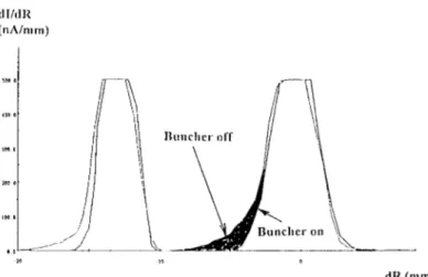
In order to reduce the width of the last turn at extraction of SSC2, a new rebuncher (R2 on figure 1) was designed [6] and put in operation. The result of its action on a low peak-intensity beam is illustrated on figure 2.
<ll/dR (nA/m01)
dR (0101)
Figure 2 . Pattern of the last two turns at SSC2 extraction with and without rebuncher R2
2.3 The stripper
In order to increase the stripper lifetime without defocusing the beam, the whole foil-holder was made to rotate at 0.01
rpm in a plane perpendicular to the beam so as to use a larger area of the carbon foil. In the rotation, the phase of the bunch at SSC2 injection is only slightly affected by foil inhomogeneities (± 0.16 RF degrees) and this excursion can easily be compensated by a feedback action on the bias voltage applied to the stripper.
2.4 The tuning method
Several methods are possible to step-by-step tune the accelerator for high intensity, starting from a low level: a) act on the source tuning, or on a collimator at its output, b) act on emittance defining slits, either in the axial injection beam line, or in Ll (see fig 1) where the 1 MeV/n beam is still almost harmless and c) use a chopper of which the duty-cycle is increased by steps up to a DC mode.
Methods a) and b) modify the beam density distribution in phase space as well of course as the peak intensity. Method c) would have been the best and the most straightforward, had we succeeded in replacing all the existing secondary emISSIOn beam profile monitors (SEBPM) by non-interceptive ones based on ionisation of the residual gas and collection on micro-channel plates (MCPBPM). Although this second type of BPM works perfectly to control steady beams [7] , they appeared to be too fragile when tuning a beam with occurrences of large variations in direction, focusing and intensity. On the other hand, protection of the SEBPM requires such a low duty-factor for the chopper that profiles become hardly measurable. It was therefore decided to:
1) tune the beam at low intensity with a combination of pepper-pot and chopper and
2) once the BPMs are removed, remove also the pepper-pot and increase the intensity step by step with the chopper.
3. RESULTS OF BEAM TESTS AND PERPECTIVES
The test beam is 36 ArIO+1l8+ accelerated at 95 MeV/u. The
intensity extracted from the ion source at 80 kV and in a 60 x 60 1t rum mrad emittance is of the order of 5xlO 13 pps,
which should be sufficient to reach 1.lxlO 13 pps at SSC2
output, corresponding to a power of 6 kW. Efforts still have to be made in order to get a better stability of the source. Transmission efficiencies of the injector cyclotron, of SSC 1 and of beam lines L 1 and L2 are acceptable [4].
However, when testing the method described above, it appeared immediately that the machine tuning is depending on the peak value of the intensity : the transmission efficiencies of SSCI and SSC2 drop by an important factor when the pepper-pot is removed, even for an intensity maintained to a low average value by the chopper. As the chopper duty-cycle is increased, parameters essentially related to the buncher, rebunchers and RF systems have to be readjusted and the transmission through SSCI can be recovered above a 95 % level, but the losses at extraction of SSC2 are increasing up to an unbearable level (200 watts) when the beam intensity exceeds 5xlO 12 pps.
Method b), consisting in tuning SSCI and SSC2 using the admittance slits in Lias a monitor for the beam intensity, lead to the same limitation (figure 3).
Intensity extracted from CSS2 ( Ar 36, 95 MeVln)
O,E+OO +---l---... - - - I o - -... - ... MNNLNLNNNMセ@
o 2 4 6 10 12
Admittance of beam line Ll (Pi x mm mrad)
Figure 3, Intensity extracted from SSC2 as a function of the admittance of beam line Lt.
14
It was then decided to develop a two-fold strategy : a) consolidate a steady 2 kW beam power operation (this will require an adaptation of the production target geometry to this value). This was performed during a beam in June 1998 : the best result was a 4xlO 12 pps (about 2.2 kW) beam
for about 8 hours, with a 96 % transmission efficiency of SSC2. However, sparks issuing from upstream electrostatic or RF devices were triggering the safety interlock system too often : since then, an electronic circuit that automatically sets the system back after a lOOms delay has been satisfactorily tested and a smooth operation was obtained,
b) get a better understanding of the « peak intensity effect». Although beam optics computations had shown [8] that space charge was playing a minor role except in the injector
cyclotron CO 1 below 100 ellA, a series of tests is going to be undertaken, with the collaboration of Th. Stammbach from PSI, in order to evaluate and counteract a possible longitudinal effect. Three possible cures can then be tested :
- generate strongly bunched beams [9] into the injector cyclotron
- correct for this effect in SSC2 by changing the RF phase and,
- cut phase tails with slits.
An additional puzzling phenomenon has to be taken care of: the beam transverse emittance out of the injector CO 1 is much larger than could be predicted and is almost independent of the input emittance. We plan to recalculate the optics in COl with the modem tools developed for SPIRAL [10] in order to determine the proper injection conditions (correlations). From this study, we expect the following benefits for the high intensity operation:
- better transmission efficiency in Ll (presently 70 %)
- lower requirements on source intensity, which would then lead to a reduction of space charge forces - more leeway for the beam in the SSCs admittance.
4. SUMMARY
The accelerator complex is now almost fully protected against possible accidents caused by beams of several kW, The transmission efficiency is not a problem up to the extraction region of SSC2, where unexpected losses are observed, A steady 2 kW beam is expected to be used for production of exotic nuclei when SPIRAL is put in operation in 1999. Meanwhile, beam tests are underway for a better understanding of the cause of the losses and for finding methods to ensure the proper transmission efficiency ,
ACKNOWLEDGEMENTS
The author would like to express his thanks to all the accelerator physicists, engineers, technicians and operators of the Technical Group, the Operation Group and the SPIRAL team for their deep involvement and persisting efforts in pursuing this project.
REFERENCES
[I] lL. Baelde, E.Baron, C. Grunberg & A.Joubert - SISSI : a new tool for radioactive beams. Nouvelles du GANIL n° 44, February 1993, pp59.
[2] M. Lieuvin and the SPIRAL group. - Status of SPIRAL, the radioactive beam project at GANIL. Proceedings of the 14th Int. Conf. on Cyclotrons and their Applications. Cape Town (1995), pp651-658. Ed : lC. Cornell. Publisher: W orId Scientific.
[3] M.P, Bourgarel and the SPIRALIGANIL groups. -SPIRAL facility : first results of the CIME cyclotron obtained with stable ion beams. These proceedings
[4] E. Baron and the GANIL Staff - Upgrading the GANIL facilities for high-intensity heavy ion beams (T.H.I. Project). Ref [2], pp39-44.
[5] C. Jamet et E. Petit - Recent developments for beam intensity operation. These proceedings
[6] M. Di Giacomo. - Design and manufacturing tools for RF resonators at GANIL. These proceedings
[7] R. Anne , J-L. Vignet, Y. Georget, R. Hue, C. Tribouillard. - Beam profile and beam time structure monitors for the extracted beams from the GANIL cyclotrons. These proceedings
[8] E. Baron, R. Beck, M.P. Bourgarel, B. Bru, A. Chabert, Ch. Ricaud. - High intensity and space charge problems at
GANIL.Ilth Int. Conf. on Cyclotrons and their Applications, Tokyo (1986) pp234-237. Ed: M. Sekiguchi, Y. Yano and K. Hatanaka. Publisher: lonics.
[9] Th. Stammbach - Experience with the high current operation of the PSI cyclotron facility. 13th lnt. Conf. on Cyclotrons and their Applications, Vancouver (1992). pp28-35. Ed: G. Dutto , MK Craddock. Publisher: World Scientific.
[10] P. Bertrand, D. Bibet, M.P. Bourgarel, B. Bru, A. Chabert, F. Daudin, M. Duval, M. Ozille, Ch. Ricaud, F. Varenne - Ion beam simulation and optimisation method used for the CIME cyclotron injection. These proceedings.