HAL Id: cea-02339105
https://hal-cea.archives-ouvertes.fr/cea-02339105
Submitted on 13 Dec 2019HAL is a multi-disciplinary open access
archive for the deposit and dissemination of sci-entific research documents, whether they are pub-lished or not. The documents may come from teaching and research institutions in France or abroad, or from public or private research centers.
L’archive ouverte pluridisciplinaire HAL, est destinée au dépôt et à la diffusion de documents scientifiques de niveau recherche, publiés ou non, émanant des établissements d’enseignement et de recherche français ou étrangers, des laboratoires publics ou privés.
Towards a Development of Online Chemical Analyses
C. Michel, J.-V. Guillaubez, C. Castano, S. Schuller, D. l’Hermite, R.
Didierlaurent
To cite this version:
C. Michel, J.-V. Guillaubez, C. Castano, S. Schuller, D. l’Hermite, et al.. LIBS Measurement in Vitrification of HLW Process Towards a Development of Online Chemical Analyses. WASTE MAN-AGEMENT 2018, Mar 2018, Phoenix, United States. �cea-02339105�
1
LIBS Measurement in Vitrification of HLW Process: Towards a Development of Online Chemical Analyses - 18290
Caroline Michel*, Jean-Valéry Guillaubez*, Carine Castaño*, Sophie Schuller*, Daniel L’Hermite**, Régis Didierlaurent***
*CEA,DEN,DE2D,SEVT, Laboratoire de Développement des Procédés de Vitrification, CEA Marcoule, BP 171, 30207 Bagnols sur Cèze, France
**CEA,DEN,DPC,SEARS, Laboratoire de développement Analytique Nucléaire, Isotopique et Elémentaire, F-91191 Gif-sur-Yvette Cedex, France
*** AREVA NC Laboratoire Commun de Vitrification, CEA Marcoule, F-30207 Bagnols sur Cèze, France
ABSTRACT
Research programs are currently underway in the Joint CEA-AREVA Vitrification Laboratory (LCV) to develop and optimize Laser Induced Breakdown Spectroscopy (LIBS) for nuclear waste streams analyses. The laboratory has full scale prototypes with the advantage of working on simulated inactive solutions of fission products.
LIBS is an elemental chemical analysis technology that uses a short laser pulse to create a micro-plasma on the sample surface. This analytical technique offers many advantages compared to other techniques. It includes a sample preparation-free measurement and an extremely fast measurement time, from a few seconds to a few minutes. This paper presents the LIBS technique available in the laboratory. The first LIBS analyzes results of liquid samples from the off-gas treatment unit integrated on the full scale vitrification process are also presented and discussed. These complex solutions contain suspended particles and up to 30 chemical elements. A vision of an online LIBS analysis cell is also proposed with the development and associated research steps.
INTRODUCTION
In France, vitrification of fission products solutions is implemented at the La Hague site. The Joint Vitrification Laboratory at the CEA provides technical support to the La Hague plant in order to improve the process on all vitrification units. The laboratory has full scale prototypes with the advantage of working with surrogate inactive solutions of fission products. To control and operate the process, many online tools have been developed but none of them are able to give chemical information such as elemental composition. This kind of measurement could give real-time crucial information about the process operation (nominal and transient modes). These data could also be used for the hydrodynamic modeling. Actually, during a vitrification test, many samples are collected and analyzed by other laboratories and results are provided at a later stage. LIBS (for Laser Induced Breakdown Spectroscopy) is an elemental chemical analysis technology that uses a short laser pulse to create a micro-plasma on the sample surface. This analytical technique offers many advantages compared to other techniques. It includes a sample preparation-free measurement and an extremely fast measurement time, from a few seconds to a few minutes. In this context, LIBS can be relevant for continues real-time analyses of components in the several streams from vitrification of HLW processes.
METHODS
On one hand, in this part, the vitrification process currently used in the laboratory is presented. The sampling points are also presented along with their interests. On a second hand, the LIBS technique is presented and relevant information about adapting this technique on-line is introduced.
2
Chemical analysis in the vitrification prototype
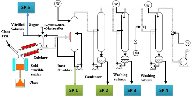
Flowsheet of the vitrification process implemented in the laboratory is reported in Fig. 1. During a calcination and vitrification test a lot of samples are collected from the fission product solution to the liquid recovered from the off-gas treatment unit. In Figure 1, Sampling Point (SP) of interest for LIBS technique analysis are represented.
The off-gas treatment unit is first composed of a dust scrubbed which is the first step where gases from calcination and melter units are directed. It consisted in impacting water crosscurrent with the gas flow. A part of the solution from the dust scrubber is recycled to the top of calcination unit. Gases from the dust scrubber are directed in a condenser which is the second step of the off-gas treatment unit. Incondensable gases are then directed to two other washing columns before stack release.
Fig. 1: Vitrification prototype unit with the sampling point referenced
Samples are collected from all equipment of the off-gas treatment system (SP 1 to 4). Dust scrubber and condenser units are identified as sensible point of chemical analysis. Indeed, more than 90% of chemical element is trapped in these units. The LIBS technique for real time information of chemical composition has been first studied for these two pieces of equipment (dust scrubber and condenser).
LIBS is also strongly contemplated to identify and quantify some elements of interest within Fission Product (FP) solutions (SP 5). FP reference solutions (in France UOx, UMo solutions [2-3]) will be used to improve LIBS analysis on this type of solutions and to evolve the analysis toward not –well-known solutions. Real time knowledge of the feed composition is crucial in particular when liquid waste streams has a high variability in terms of chemical composition (for instance effluents from decommissioning and dismantling operations).
LIBS technique
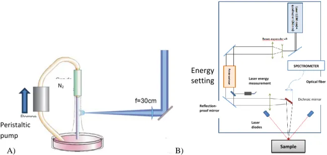
The LIBS equipment available at the laboratory (LCV) is composed of a Nd-YAG laser with a fundamental wavelength of 1064 nm. For the purpose of liquid analysis, the laser wavelength is quadrupled to UV wavelength 266 nm. The optical scheme from the laser source to the sample is represented in Fig 2-B). Emission photons are collected by an optical fiber and driven to a spectrometer (Andor Solis i-star). The spectrometer offers a wide range of wavelength (250 to 950 nm) that allowed the detection of several chemical elements in one shot. The quality of the analysis and the accuracy of the measurement are directly related to the acquisition parameters of the LIBS measurement. Acquisition parameters are listed below:
SP 1 SP 2 SP 3 SP 4
3 - Time delay: time between the laser shots and the beginning of photon’s collection (500-5000 ns
range)
- Gate: duration of photons’ acquisition (1-10 µs range)
- Laser Energy: concentrated ablation energy at the focal point on the sample (depending on the laser wavelength 3 to 60 mJ)
Circulation of liquid sample is represented on Fig 2-A). Liquid sample circulate through a peristaltic pump. The liquid is sent into an injection nozzle to form a stream stabilized by a nitrogen cladding. The focus of the laser is tangential to the gravitational flow.
A) B)
Fig. 2: A) liquid-jet technique for LIBS analysis. B) Optical scheme of the laser from the laser source to the sample
LIBS configuration and chemical composition of samples collected from the dust scrubber and condenser
LIBS equipment in the laboratory worked with a UV laser. UV laser provide a better sensitivity for element detection but this configuration is relatively impacted with the industrial environment (vibration, temperature). This point will be discussed later in the “on-line development” part. Acquisition parameters (time delay, energy and gate) have been evaluated and optimized to obtain a better compromise between the number of elements detected and the limit of detection for the concentration of each element. The result of an analysis by LIBS is the average of 25 sequences. Each sequence is 15 seconds of laser shots (laser frequency 20 Hz) which represented an accumulation of 300 laser shots.
The liquids collected from the dust scrubber and the condenser, are relatively different in terms of composition and visual aspect. These information are gathered in Table 1 for both equipment.
Table 1: Aspect and composition of solutions collected in the dust scrubber and the condenser
Dust scrubber Condenser
Color Brown Translucent
Solid in suspension 400 mg/L -
Salinity 20 g/L < 1 g/L
Acidity 4-5 N 2 N
Element analyzed Cs, Re, Ru Cs, Re
SPECTROMETER Optical fiber Dichroic mirror Laser diodes Reflection-proof mirror Laser energy measurement Sample Energy setting Peristaltic pump N2
4 Dust scrubber and Condenser samples are composed of most chemical elements (more than 20) but in this paper the emphasis was put in the detection of Re, Cs and Ru.
In order to highlight the effect of the presence of particles in suspension in the samples from the dust scrubber, the analysis was conducted twice. A first time without any stirring to analyse only the clear part and a second time with stirring. This difference will be shown in “results” part.
RESULTS AND DISCUSSION Condenser samples analysis
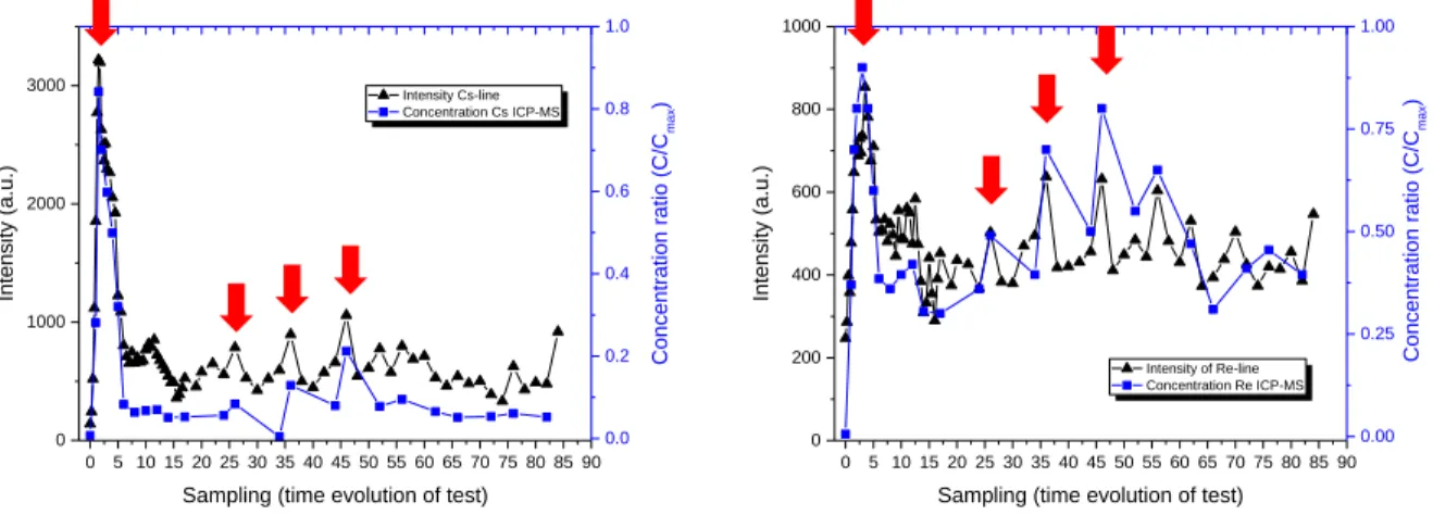
Analysis of dust scrubber and condenser samples by LIBS are presented and compared with ICP-MS analysis in the following Figure 3. Results are first presented for condenser samples and represented with raw results extract from LIBS analysis which is intensity of lines as a function of time during a vitrification test. 0 5 10 15 20 25 30 35 40 45 50 55 60 65 70 75 80 85 90 0 1000 2000 3000 Intensity Cs-line Concentration Cs ICP-MS
Sampling (time evolution of test)
Int en sity (a .u. ) 0.0 0.2 0.4 0.6 0.8 1.0 Conce ntr atio n r atio (C/C m ax ) 0 5 10 15 20 25 30 35 40 45 50 55 60 65 70 75 80 85 90 0 200 400 600 800 1000 Intensity of Re-line Concentration Re ICP-MS
Sampling (time evolution of test)
Int en sity (a .u. ) 0.00 0.25 0.50 0.75 1.00 Con cen tra tion ra tio ( C/C m ax )
Fig. 3: Comparison of LIBS intensities of Cs and Re with ICP-MS results for condenser samples As it is shown in Fig. 3, there is a good correlation between LIBS intensity of lines for Re and Cs and ICP-MS results. Indeed, profiles of concentration are well represented by intensity evolution. Moreover, concentration peak, represented with red arrows in Fig. 3, corresponded with intensity peak. These pics are due to different operating modes during the vitrification test (transient modes amongst others). These results shown that LIBS analysis are quite sensitive to represent these operating modes.
Dust scrubber samples analysis
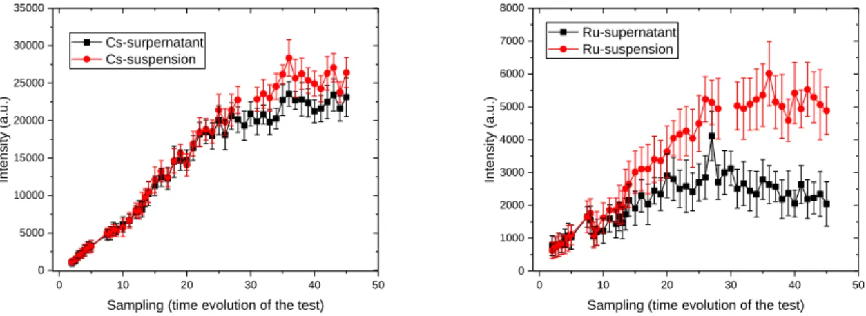
The effect of particle in suspension is shown in Figure 4. Intensities of Cs and Ru elements are shown in these graphs and compared between supernatant analysis (without stirring) and suspension (with stirring). At the beginning of the test, there is no difference with analysis performed with or without stirring and for both elements. The difference appeared clearly after time 20 for Ru since intensities from suspension analysis become higher than supernatant analysis. This is due to the fact that particles are composed mainly of Ru and begin to accumulate in the samples. When laser ablation crosses a particle, an enhancement of signal occurred. Indeed, for the same ablation energy, the surface of a solid will be more effectively ablated than a liquid and involving more photons of emission collected. Because of the dispersion of particle in solution, the standard deviation of Ru intensity in suspension is higher than those in supernatant.
5 0 10 20 30 40 50 0 5000 10000 15000 20000 25000 30000 35000 Int en sity (a .u. )
Sampling (time evolution of the test) Cs-surpernatant Cs-suspension 0 10 20 30 40 50 0 1000 2000 3000 4000 5000 6000 7000 8000 Int en sity (a .u. )
Sampling (time evolution of the test) Ru-supernatant
Ru-suspension
Fig. 4: Effect of particles in suspension for LIBS analysis with dust scrubber samples
The comparison of profile between LIBS intensities of element with concentration (ICP-MS) is reported on Figure 5. ICP-MS analysis was performed on filtered dust scrubber solutions. LIBS analysis on these solutions were performed without any stirring to compare directly with ICP-MS results. Standard deviation were not reported on this graphs for clarity of lecture.
0 5 10 15 20 25 30 35 40 45 50 55 60 65 70 75 80 85 90 0 20000 40000 Intensity Cs-line Concentration Cs - ICP-MS
Sampling (time evolution of the test)
Int en sity (a .u. ) 0.00 0.33 0.67 1.00 Conce ntr atio n r atio (C/C m ax ) 0 5 10 15 20 25 30 35 40 45 50 55 60 65 70 75 80 85 90 0 1000 2000 Intensity Ru-line Concentration Ru ICP-MS
Sampling (time evolution of the test)
Int en sity (a .u. ) 0.00 0.08 0.17 0.25 0.33 0.42 0.50 0.58 0.67 0.75 0.83 0.92 1.00 Conce ntr atio n r atio (C/C m ax )
Fig. 5: Comparison of LIBS intensities of Cs and Ru with ICP-MS results for dust scrubber samples The evolution of LIBS signal for both element is correlated to the concentration. Same as condenser concentration profile, peaks of concentration were observed during the test and corresponding to peaks of intensity on the signal obtained by LIBS. These results also allowed setting calibration curves in the samples matrix in order to avoid any matrix effects which are well known in LIBS analysis [4-5]. Calibration curve for Cs is reported in Figure 6.
6 0.00 0.33 0.67 1.00 0 20000 40000 Int en sity Cs (a . u .)
Concentration ratio Cs ICP-MS (C/Cmax)
2180 89 . 8 C I 988 . 0 2 R
Fig. 6: Calibration curve of Cs obtained with LIBS analysis
Toward a development of an on-line analysis cell and an adaptation of LIBS laser
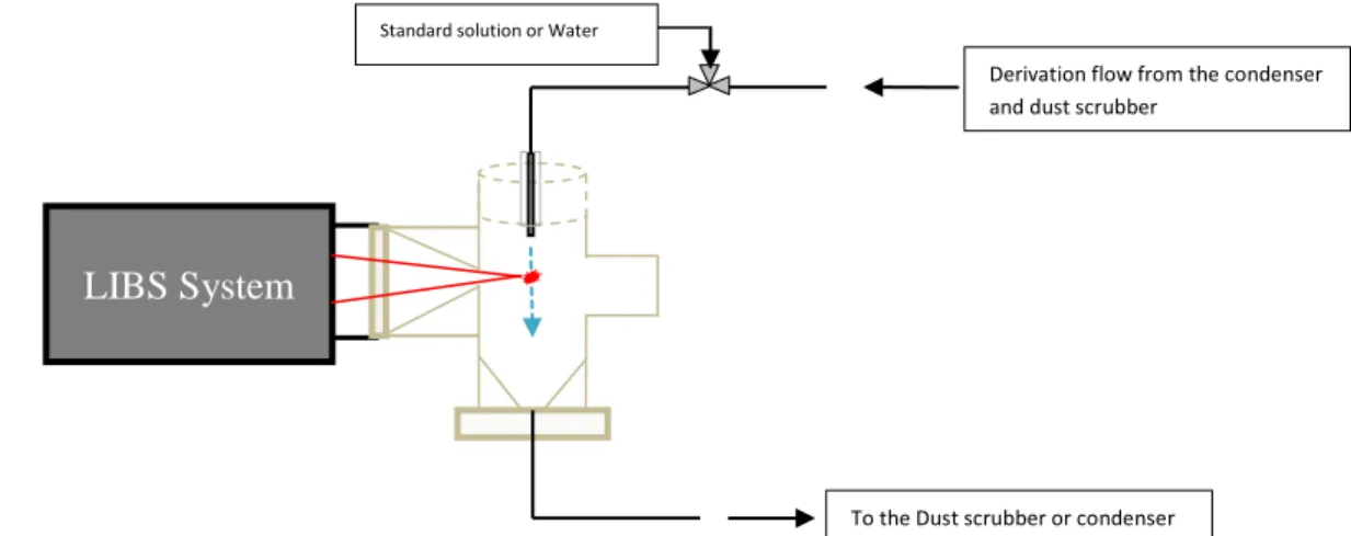
These encouraging results on the laboratory analysis equipment of the LIBS led to the design of an analysis cell adapted to online LIBS measurements. Research is currently being carried out to work on the LIBS IR which is more adapted to the industrial environment in order to guarantee performances at least identical to UV. A schematic diagram of of the online cell operation is presented in Figure 7. Future tests will be dedicated to the qualification of the cell on a recirculation loop. To detect any deviation of the system, a 3-way valve is considered to circulate a standard calibration solution and thus adjust the device.
CONCLUSION
LIBS-UV has proved to be an effective analytical device for the detection of the elements present in the off-gas treatment system of vitrification processes. Indeed, the liquid samples from the first two equipment (dust scrubber and condenser) were analyzed without any preparation. A lot of samples collected during vitrification tests were analyzed and the LIBS signal of element lines were compared with concentration (from ICP-MS). A good correlation was obtained between the concentration profiles
LIBS System
Derivation flow from the condenser and dust scrubber
Standard solution or Water
To the Dust scrubber or condenser
7 and the LIBS intensities for the elements of interest presented in this paper (Cs, Re and Ru). These studies also showed the influence of the presence of solid particles in the solution on the analysis. The increase of the LIBS signal for Ru due to the ablation of these solid particles, composed mainly of Ru, causes an increase in the standard deviation of the analysis. An algorithm could be considered to detect the analysis sequences influenced by the presence of particles and extract the data to consider only the supernatant fraction.
Calibration curves were made for element of interest. Matrix effects occur in LIBS analysis and require calibration to be performed with real samples. Free-calibration methods are well studied today with solid samples and could be extended to liquid analysis [5-6].
Online deployment of this technique still requires intermediate steps that are listed below: 1- Qualification of online analysis cell on a closed recirculation loop
2- Optimization of IR LIBS analysis to guarantee detection limits close to those obtained with UV in the real solutions of the process
As it is mentioned before, LIBS is strongly contemplated to identify and quantify some elements of interest in Fission Product (FP) solutions (SP 5 in Fig. 1). For that purpose, further feasibility studies will be carry out with simulated FP solutions (UMo, Uox reference FP). The approach will be quit different since here there is no transient phase on the flow stream. Methods such as free calibration and neural networks will be considered.
REFERENCES
[1] C. Ladirat, J-F. Hollebecque, and E. Chauvin, WM2015 Conference 2015, USA
[2] O. Delattre, E. Régnier, S. Schuller, M. Allix, G. Matzen, Image analysis study of crystallization in two glass compositions of nuclear interest, Journal of Non-Crystalline Solids 379 (2013) 112-122 [3] O. Pinet, J.F. Hollebecque, F. Angeli, P. Gruber, Vitrification of Molybdenum-Rich High-Level Solutions by the Cold Crucible Melter Process, WM2011 Conference, Phoenix, AZ (2011)
[4] N.K. Rai, S. Pandhija, S. Rai, A.K. Pathak, A.K. Rai, Effect of Analyte Concentration on the Laser-Induced Plasma Temperature and Electron Density in Liquid Matrix, Spectroscopy Letters 46 (2013) 218-226.
[5] T. Takahashi, B. Thornton, Quantitative methods for compensation of matrix effects and self-absorption in LIBS signals of solids, Spectrochimica Acta Part B: Atomic Spectroscopy 138 (2017) 31-42.
[6] B. Praher, V. Palleschi, R. Viskup, J. Heitz, J.D. Pedarnig, Calibration free laser-induced breakdown spectroscopy of oxide materials, Spectrochimica Acta Part B: Atomic Spectroscopy 65 (2010) 671-679.