HAL Id: hal-01845188
https://hal.archives-ouvertes.fr/hal-01845188
Submitted on 28 Feb 2020HAL is a multi-disciplinary open access archive for the deposit and dissemination of sci-entific research documents, whether they are pub-lished or not. The documents may come from teaching and research institutions in France or abroad, or from public or private research centers.
L’archive ouverte pluridisciplinaire HAL, est destinée au dépôt et à la diffusion de documents scientifiques de niveau recherche, publiés ou non, émanant des établissements d’enseignement et de recherche français ou étrangers, des laboratoires publics ou privés.
Joining Silicon Carbide Plates by Titanium
Disilicide-Based Compound
Elodie Jacques, Y. Le Petitcorps, Laurence Maillé, Christophe Lorrette, L.
Chaffron
To cite this version:
Elodie Jacques, Y. Le Petitcorps, Laurence Maillé, Christophe Lorrette, L. Chaffron. Joining Silicon Carbide Plates by Titanium Disilicide-Based Compound. Powder Metallurgy and Metal Ceramics, Springer Verlag, 2014, 52 (9-10), pp.606 - 611. �10.1007/s11106-014-9567-5�. �hal-01845188�
Joining Silicon Carbide Plates by Titanium Disilicide-Based Compound
E. Jacques1, Y. Le Petitcorps1, L. Maillé1, C. Lorrette1,2 and L. Chaffron21
University of Bordeaux, Laboratoire des Composites Thermostructuraux, UMR 5801, 3 Allée de la Boétie, 33600 Pessac-France
2
CEA-Nuclear Energy Division, Nuclear Material Department, Section for Applied Metallurgy Research, Technology for Extreme Materials Laboratory
KEY WORDS: Brazing silicon carbide, Ceramic metal interface, Ceramic Matrix Composites, Intermetallic and disilicide compounds.
ABSTRACT
The present work is part of the Fourth Generation reactors program where is described the methodology and the results for joining SiC substrates by metallic silicides with SiC powder reinforcements. The more severe temperature in service are in the range of 1000°C but short time incursions at 1600 or 2000°C have to be anticipated. One of the key issues is the joining of the SiCf/SiCm composites to seal the combustible
cladding. We describe the results for joining SiC substrates at liquid state using TiSi2. Joint integrity and
joint strength can be improved by adding small SiC particles to the silicides powders. The assemblies are performed in an inductive furnace. Cross sections of the assembly, wettability tests, thermo-mechanical properties and 4-bending point mechanical tests are presented.
1. INTRODUCTION
Joining ceramic/ceramic composites (CMC’s) is of interest for numerous applications in the aeronautic or nuclear fields. This joining may concern the assembly of two CMCs parts or the assembly of one CMC part against a metallic alloy. This study deals with the assembly of two silicon carbide/silicon carbide composite plates designed for a fuel cell component within the framework of the Fourth Generation Reactor Program [1]. In order to achieve this goal, many requirements have to be followed: (i) the joint must be tight enough to avoid the gas leaks in service and, (ii) has to withstand temperatures such as 1000°C for very long durations (service conditions) and 1500°C for short durations (accidental conditions) without damaging the CMC properties, (iii) the process has to be compatible with the nuclear constraints and must not damage the composite properties which are very sensible to fibre degradations. The composite material for this application is made of a woven silicon carbide fibre perform (Hi-Nicalon
Type STM or Tyranno SA3TM fibre) infiltrated by a silicon and carbon based precursor (CVI process). Both the matrix and the fibre are nearly pure silicon carbide which gives to the composite a good thermal stability up to 1600°C. The CMCs assembly research is not a new but this requirement in temperature stability (1500°C) makes the answer not trivial [2-5]. Conventional silicon based compositions cannot be used since the melting point of Si is too low. Thus a material selection study has been done in order to select compounds able to withstand these requirements. The selection of the right composition for the joint has been done from the physical properties, the thermodynamic data of the different candidates in order to avoid a too important mechanical and chemical mismatch with the silicon carbide. Various assembly processes have been evaluated (solid state bonding, liquid state bonding) and several ways of short heating have been tested (microwave, High Frequency heating). The quality of the assembly has been evaluated through metallographic observations on polished sections or with tomography images on the whole assembly.
2. MATERIALS AND METHODS
2.1. Material selections
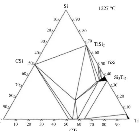
The silicon carbide material is a covalent crystal characterised by a low coefficient of thermal expansion CTE, a high modulus, a high melting point and a intermediate toughness which makes the ceramic sensible to flaws (Table 1). Unfortunately the silicon carbide reacts at medium temperature (above 800°C) with most of the refractory metals. Thus these metals cannot be chosen which purpose. However the analysis of the ternary phase diagram involving Si, C and Metallic atoms indicates that some compositions can be in a thermodynamical equilibrium with SiC (Figure 1). The carbide (here TiCx) and
the disilicide (here TiSi2) are thermodynamically stable with SiC in the solid state whereas the other
silicides react with SiC. In addition to a poor thermal expansion mismatch with SiC, TiC has not been chosen due its too high melting point which could be a problem if the joint has to be melted for the assembly. The remaining choice is the metallic disilicide. This disilicide is related to a ionic-covalent crystals which exhibits an intermediate Young’s modulus and a higher CTE than SiC. Due to this CTE mismatch, the joint will be in tension and the silicon carbide in compression on cooling. One way to reduce the CTE of the joint is to incorporate SiC particles within the silicide. By controlling the volume fraction of SiC added, the CTE and the Young’s modulus can be tailored. Due to the relatively high thermal stability of TiSi2, this disilicide has been selected. The TiSi2 compound will be reinforced by SiC
particles (less than 1m in size) and with different volume fraction (from 0 to 30%).
Since the disilicide do not react with the silicon carbide substrate in the solid state, the bonding between the joint and the SiC substrate should not be strong enough. In order to get this bonding, the melting of the joint should be done very rapidly in order to promote and to limit the chemical reaction with the silicon carbide substrate. A microwave furnace (2450MHz) can be used for melting ceramics which have an effective electrical conductivity between 1 and 10 Sm-1 such as semi-conductors. It is supposed to be a more economical process than the other conventional processes like the high frequency induction furnace. The principle was to selectively heat the joint and not the silicon carbide substrate. Thus the joint could be melted without heating the composite itself. Unfortunately the silicon carbide absorbs at the same wave than the titanium disilicide. Finally, a more conventional high frequency furnace has been chosen (60% of power – Five Celes HF MP3, 12kW). With that equipment, the joint between two silicon carbide plates is melted in less than 1 minute and cooled down for few seconds later after the melting. The assembly is maintained by a graphite susceptor inside a chamber under a purified argon atmosphere. The wettability is of great importance in the brazing technology and has been studied for the different compositions by recording the value of the contact angle during the spreading of the drop.
2.3. Material characterisations
In order to characterize the physical properties of the joint (CTE and Young’s modulus) model materials of TiSi2 + x% of SiCp were prepared by spark plasma sintering. After sintering, the materials were nearly
fully dense (95% of the theoretical density). The CTE has been measured by a TMA device (dilatometer Netzsch DIL402C) and the Young’s modulus measured from the room temperature to 1000°C was determined by a Grindosonic apparatus (LEMMENS Inc.).
The quality of joining has been studied on polished cross sections by SEM and WDS analysis (Hitachi S4500). A particular attention has been paid to the occurrence of cracks in the joint, the thickness of the reaction zone between the melted joint and the SiC substrate, as well as its chemical composition. The macroscopic characterisation of the joint has been done by X ray tomography (Phoenix X Ray nanotom S).
3. RESULTS AND DISCUSSIONS
3.1. Decreasing the residual stresses in TiSi2 by the addition of submicronic SiC particles (SiCp)
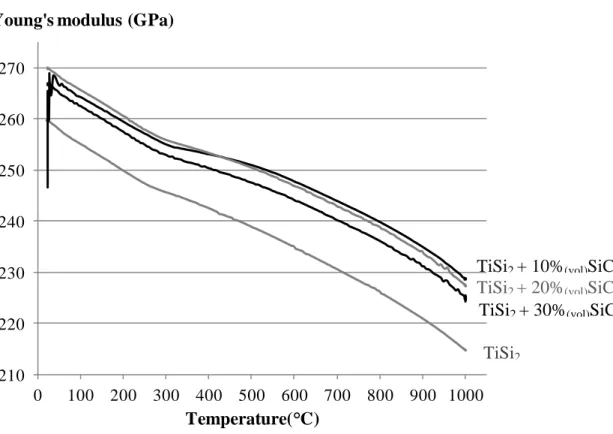
Although the values are below the data expected from a rule of mixture (ROM), the SiCp have a positive
effect on the Young’s modulus from room temperature to 1000°C (Figure 2). This difference from the ROM can be explained by the submicronic size of the particles, the aspect ratio of them which is closed to one and the presence of 5% of porosities. A 10% decrease in the CTE is also measured on TiSi2
The consequences on the network of cracks in the joint can also be seen on figure 3. In order to avoid a chemical reaction between the TiSi2 and the SiCfrom both the particles and the substrate, the material
was also prepared by spark plasma sintering at 1200°C. The presence of the SiC particles induces a decrease in the residual stresses within the joint which exhibits also a clear interface with the silicon carbide substrate.
3.2. Wettability of TiSi2 + SiCp
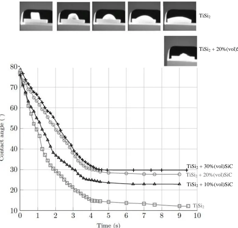
For pure TiSi2, the contact angle decreases from 80° to 12°, 4 seconds after the melting (Figure 4) TiSi2
has a very low contact angle which is very useful for its infiltration in small cavities of the materials to join. The reason of this kinetic of wettability can be explained by the reactivity of the liquid Ti-Si alloy with the SiC substrate [8]. When SiC particles are added, the contact angle is increased to 30° for 30%Vo. of SiCp after 4 seconds in the liquid state. The particles induce an increase in the viscosity as well as they
react with the titanium disilicide matrix. However, the contact angle measured with 30% of SiC is very closed to the contact angle measured with pure silicon. The contact angle and the kinetic of spreading can be taylored by the amount of SiCp. It is important to control the time during the melting step in order to
limit the reaction zone thickness between the joint and the SiC substrate.
3.3. Reactivity of liquid (Ti,Si) + SiCp with the SiC substrate
In the liquid state, the liquid containing Ti and Si atoms should react with SiC. From the SiC to the TiSi2,
the interface is composed of Ti3SiC2 and TiC (Figure 5). If the joint contains SiCp they also should react
with the liquid and the liquid should be less aggressive against the SiC substrate. Consequently, the reaction zone thickness at the Joint/SiC interface decreases with an increase in SiCp amount (Tableau 2).
3.4. Characterization of a real assembly between two plates of SiC
Two plates of SiC have been joined by melting the TiSi2 mixture and followed by a rapid cooling. It can
be seen that the brazing is nearly uniformly present even though some depletion of matter can be seen. No pressure was applied on the surface of the sample, a possible explanation of this lack of matter could be the presence of gas confined during the melting. However these first results are encouraging.
4. CONCLUSIONS
The aim of this work was to find an adequate brazing composition which is stable with SiC between 1000°C to 1500°C for long durations. Titanium disilicide can reach such a goal but due to the mismatch in the physical properties between SiC and TiSi2, the joint is drastically cracked. The addition of
other beneficial effect on the chemical stability of the joint when the disilicide is melted during the brazing step. The interest of this type of brazing has now to be confirmed by the mechanical testing of the assembly.
ACKNOWLEDGMENTS
The authors wish to thank M.Lahaye from Cecama University of Bordeaux and O. Cathy from LCTS respectively for their contributions in the chemical analysis and in the tomography characterization. The microwave experiments were done by E. Savary at Crismat (University of Caen, France).
REFERENCES
1. L. Chaffron et al. Innovative SiCf/SiC composite Materials for Fast Reactor Application, ,
Transactions of the American Nuclear Society, ANS annuel meeting, San Diego 2010.
2. B. Riccardi, C.A. Nannetti, T. Petrisor, J. Woltersdorf. High temperatures brazing for SiC and SiCf/SiC ceramic matrix composites, International Symposium on SiCf/SiC composites materials
research and development 2002.
3. B. Riccardi, C.A. Nannetti, T. Petrisor, J. Woltersdorf. Issues of low activation brazing of
SiCf/SiC composites by using alloys without free silicon. Journal of Nuclear Materials 2004; 329:
562–566.
4. B. Riccardi, C.A. Nannetti, T. Petrisor, M. Sacchetti. Low activation brazing materials and techniques for SiCf/SiC composites, Journal of Nuclear Materials 2002; 307: 1237–1241.
5. E. Jacques, L. Maillé, Y. Le Peticors, C. Lorrette, C. Sauder. Preliminar results on joining of thin SiC/SiC composites by silicides coumpounds and local heating, Ceramic Engineering and Science Proceedings 2011; 32: 73-83
6. Materials Handbook, A concise Desktop Reference, F. Cardarelli, Springer, ISBN 1-85233-043-0.
7. Handbook of ternary alloy phase diagrams 1995.
LIST OF FIGURE AND TABLE CAPTIONS
FIGURES
Figure 1: Ternary Phase diagram of Ti, Si,C plotted at 1500K [7]
Figure 2: Young’s modulus versus the temperature for TiSi2/SiC systems with different content of
additions
Figure 3: Crack pattern in the TiSi2 joint reinforced with 10 and 20%Vo. of SiCp
Figure 4: Wettability studies for different compositions of TiSi2 and SiCp
Figure 5: Reaction Zone thickness and morphologies at the SiC/TiSi2 interface
Figure 6: X-Ray tomography images of the brazing between two plates of SiC
TABLES
Table 1: Physical Properties of the potential candidates for joining SiC [6]
TABLE 1
Si SiC TiSi2 TiC
Melting (°C) 1414 2700 1540 3140
CTE (10-6/K) 5.7 4.5 10.4 7.6
Young’s Modulus (GPa) 130 400 260 450
TABLE 2
Pure TiSi2 TiSi2+
10%SiC Vo. TiSi2+ 20%SiC Vo. TiSi2+ 30%SiC Vo. Reaction zone thickness (m) 20 6-7 4-5 4-5
FIGURE 1 Si 1227 °C CSi C CTi Ti TiSi2 TiSi Si3Ti5 90 80 70 60 50 40 30 20 10 90 80 70 60 50 40 30 20 10 90 70 60 50 30 20 10 80 40
FIGURE 2 210 220 230 240 250 260 270 0 100 200 300 400 500 600 700 800 900 1000
Young's modulus (GPa)
Temperature( C)
TiSi2
TiSi2 + 10%(vol)SiC
TiSi2 + 30%(vol)SiC
FIGURE 4 TiSi2 TiSi2 + 20%(vol)SiC TiSi2 TiSi2 + 20%(vol)SiC TiSi2 + 30%(vol)SiC TiSi2 + 10%(vol)SiC