HAL Id: tel-00942559
https://tel.archives-ouvertes.fr/tel-00942559
Submitted on 6 Feb 2014HAL is a multi-disciplinary open access
archive for the deposit and dissemination of sci-entific research documents, whether they are pub-lished or not. The documents may come from teaching and research institutions in France or abroad, or from public or private research centers.
L’archive ouverte pluridisciplinaire HAL, est destinée au dépôt et à la diffusion de documents scientifiques de niveau recherche, publiés ou non, émanant des établissements d’enseignement et de recherche français ou étrangers, des laboratoires publics ou privés.
Nadia Cerezo
To cite this version:
Nadia Cerezo. Conceptual workflows. Other [cs.OH]. Université Nice Sophia Antipolis, 2013. English. �NNT : 2013NICE4149�. �tel-00942559�
ECOLE DOCTORALE STIC
SCIENCES ET TECHNOLOGIES DE L’INFORMATION ET DE LA COMMUNICATION
THESE
pour l’obtention du grade de
Docteur en Sciences
de l’Universit ´e de Nice Sophia-Antipolis
Mention :
pr ´esent ´ee et soutenue par
Nadia CEREZO
CONCEPTUAL WORKFLOWS
Th `ese dirig ´ee par Johan MONTAGNAT
soutenue le 20/12/2013
Jury :
M. Hugues BENOIT-CATTIN Professeur Rapporteur
Mme. Mireille BLAY-FORNARINO Professeur Pr ´esidente
M. Oscar CORCHO Associate Professor Rapporteur
M. Johan MONTAGNAT Directeur de recherche Directeur
List of Figures vi Listings ix Acknowledgements x Notations xii 1 Introduction 1 1.1 Simulations . . . 1 1.2 Scientific Workflows . . . 2 1.3 Challenges . . . 3 1.4 Abstraction Levels . . . 4 1.5 Entanglement of Concerns . . . 6 1.6 Goals . . . 8
2 State of the Art 10 2.1 Scientific Workflow Models . . . 11
2.1.1 Interface . . . 11 2.1.2 Model . . . 12 2.1.2.1 Graph Type . . . 12 2.1.2.2 Node Type . . . 12 2.1.2.3 Edge Type . . . 12 2.1.3 Abstraction Level . . . 15 2.1.4 Comparison Matrix . . . 15 2.1.5 Discussion . . . 17 2.1.5.1 System . . . 17 2.1.5.2 Model . . . 17 2.1.5.3 Abstraction Level . . . 17 2.2 Separation of Concerns . . . 18 2.2.1 Paradigm . . . 18
2.2.2 Main general approaches . . . 19
2.2.2.1 Subject-Oriented Programming . . . 19
2.2.2.2 Role-Oriented Programming . . . 19
2.2.2.3 Aspect-Oriented Programming . . . 20
2.2.2.4 Feature-Oriented Programming . . . 21
2.2.3 Separation of Concerns in Workflows . . . 22
2.2.3.1 Separation of Concerns in Scientific Workflows . . . 22
2.2.4 Discussion . . . 24
2.3 Model-Driven Engineering . . . 24
2.3.1 Paradigm . . . 24
2.3.2 Unified Modeling Language . . . 26
2.3.3 Model Transformations . . . 28
2.3.4 Discussion . . . 29
2.4 Knowledge Engineering . . . 29
2.4.1 Semantic Data Models . . . 30
2.4.1.1 Entity-Relationship Model . . . 30 2.4.1.2 IDEF1X . . . 31 2.4.2 Ontologies . . . 31 2.4.2.1 Types . . . 32 2.4.2.2 Languages . . . 32 2.4.3 Semantic Web . . . 32
2.4.3.1 Resource Description Framework . . . 34
2.4.3.2 RDF Schema . . . 36
2.4.3.3 SPARQL Protocol and RDF Query Language . . . 38
2.4.4 Discussion . . . 41
3 Conceptual Workflow Model 43 3.1 Conceptual Elements . . . 43 3.1.1 Conceptual Workflows . . . 43 3.1.2 Graphical Convention . . . 44 3.1.3 Encapsulation . . . 45 3.1.4 Conceptual Links . . . 47 3.2 Abstract Elements . . . 48 3.2.1 Activities . . . 49 3.2.2 Specialized Activities . . . 49 3.2.3 Links . . . 49 3.2.4 Iteration Strategies . . . 50 3.2.5 Graphical Convention . . . 51 3.3 Semantic Annotations . . . 51 3.3.1 Type . . . 52 3.3.2 Role . . . 52 3.3.3 Meaning . . . 52 3.3.4 Compatibility . . . 52 3.3.5 Graphical Convention . . . 54 3.4 Fragments . . . 54 3.4.1 Graphical Convention . . . 54 3.4.2 Variables . . . 55 4 Transformation Process 57 4.1 Mapping . . . 57 4.1.1 Mechanisms . . . 58 4.1.2 Classification . . . 58 4.2 Weaving . . . 59 4.2.1 Steps . . . 62
4.2.3 SPARQL query . . . 65 4.2.4 Conflicts . . . 66 4.2.5 Clean-up . . . 67 4.2.6 Binding . . . 68 4.2.6.1 Node-bound Weaving . . . 70 4.2.6.2 Link-bound Weaving . . . 70 4.2.7 Classification . . . 71 4.3 Tools . . . 72 4.3.1 Merging . . . 72 4.3.2 Erasing . . . 73 4.3.2.1 Conceptual Links . . . 73 4.3.2.2 Annotations . . . 74 4.3.2.3 Sub-workflows . . . 75 4.3.2.4 Example . . . 76 4.4 Discovery . . . 76 4.4.1 Process . . . 76 4.4.2 Matching . . . 77 4.4.2.1 Match Quality . . . 78 4.4.2.2 Matching Query . . . 80 4.4.3 Ranking . . . 81 4.4.3.1 Ranking Principles . . . 81 4.4.3.2 Scoring . . . 82
4.4.3.3 Ranking for Conceptual Inputs . . . 83
4.4.3.4 Ranking for Conceptual Outputs . . . 83
4.4.3.5 Ranking for Conceptual Functions . . . 84
4.5 Composition . . . 84 4.5.1 Link Suggestion . . . 86 4.5.2 Producer Suggestion . . . 88 4.5.3 Consumer Suggestion . . . 90 4.5.4 Converter Suggestion . . . 91 4.6 Conversion . . . 94 4.6.1 XML in a nutshell . . . 94 4.6.2 To GWENDIA (MOTEUR) . . . 95 4.6.2.1 Converting Inputs/Outputs . . . 96 4.6.2.2 Converting Activities . . . 96 4.6.2.3 Converting Links . . . 97 4.6.3 To t2flow (Taverna 2) . . . 99 4.6.3.1 Converting Inputs/Outputs . . . 100 4.6.3.2 Converting Activities . . . 100 4.6.3.3 Converting Links . . . 101 4.6.4 To IWIR (SHIWA) . . . 102
4.6.4.1 Converting Simple Chains . . . 102
4.6.4.2 Iteration strategies . . . 104
4.6.5 Classification . . . 106
5 Validation 109
5.1 Prototype . . . 109
5.1.1 Architecture . . . 109
5.1.2 Features . . . 110
5.2 Virtual Imaging Platform . . . 111
5.2.1 OntoVIP . . . 112
5.2.2 Workflow Designer . . . 113
5.3 Conceptual Workflow Model . . . 114
5.3.1 VIP Simulators . . . 114 5.3.1.1 FIELD-II . . . 114 5.3.1.2 SIMRI . . . 117 5.3.1.3 SimuBloch . . . 118 5.3.1.4 Sindbad . . . 118 5.3.1.5 SORTEO . . . 120 5.3.2 Simulator Template . . . 122 5.3.3 Conceptual Workflows . . . 123 5.3.3.1 FIELD-II . . . 123 5.3.3.2 SIMRI . . . 124 5.3.3.3 SimuBloch . . . 125 5.3.3.4 Sindbad . . . 126 5.3.3.5 SORTEO . . . 128 5.3.4 Discussion . . . 129 5.4 Transformation Process . . . 130 5.4.1 VIP Fragments . . . 130 5.4.1.1 Simple Sub-workflows . . . 130
5.4.1.2 Two Steps Function . . . 130
5.4.1.3 Split and Merge . . . 131
5.4.2 Use Case . . . 132
5.4.3 Discovery and Weaving . . . 133
5.4.4 Composition . . . 137 5.4.5 Conversion . . . 139 5.4.6 Discussion . . . 142 6 Conclusion 144 A Detailed Frameworks 147 A.1 ASKALON/AGWL . . . 147 A.2 Galaxy . . . 149 A.3 GWES/GWorkflowDL . . . 150
A.4 Java CoG Kit/Karajan . . . 151
A.5 Kepler/MoML . . . 152 A.6 KNIME . . . 153 A.7 MOTEUR/GWENDIA . . . 154 A.8 Pegasus/DAX . . . 155 A.9 SHIWA/IWIR . . . 155 A.10 Swift . . . 156 A.11 Taverna/SCUFL . . . 156 A.12 Triana . . . 157
A.13 VisTrails . . . 158 A.14 WINGS . . . 159 A.15 WS-PGRADE . . . 161
B Conceptual Workflow Meta-Model 163
C Fragment to SPARQL Conversion Example 166
D Two Converters Chain Query 168
E Conversion to t2flow 170 F Conversion to IWIR 176 G OntoVIP URIs 179 H License 181 Glossary 183 Bibliography 200
1.1 Scientific Workflow Abstraction Levels . . . 4
1.2 Scientific Workflow Concerns and Lifecycle . . . 7
1.3 Scientific Workflow Concerns Entanglement Example . . . 7
2.1 Control Contructs in Data-driven Models . . . 13
2.2 Data Flow in Control-driven Models . . . 14
2.3 Feature Diagram Example . . . 21
2.4 Model-Driven Architecture - Abstraction Levels . . . 25
2.5 UML Class Diagram Graphical Convention (excerpt) . . . 27
2.6 UML Class Diagram Example . . . 27
2.7 Linked Open Data cloud diagram by Cyganiak R. and Jentzsch A. . . 33
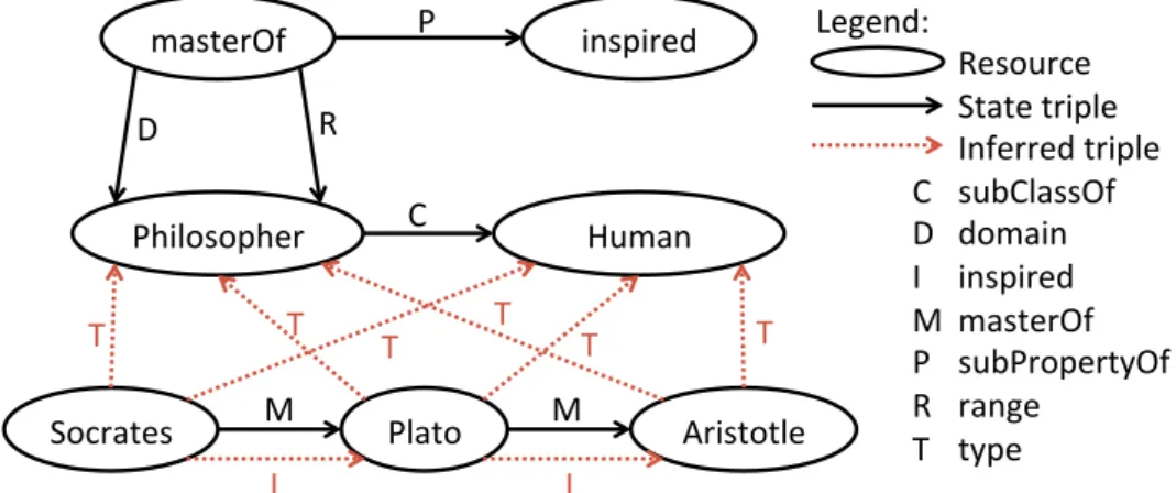
2.8 Small triple sample . . . 35
2.9 RDFS inference example . . . 37
2.10 DBpedia HTML result screenshot . . . 39
2.11 SPARQL CONSTRUCT example . . . 40
3.1 Graphical Convention - Conceptual Elements . . . 45
3.2 Image Spatial Alignment Process Example at Multiple Abstraction Levels . . . 45
3.3 Conceptual Workflow Composite Pattern . . . 45
3.4 Conceptual Link Restriction . . . 47
3.5 Data Links and Order Links Associations . . . 50
3.6 Graphical Convention - Abstract Elements . . . 51
3.7 Compatibility between Elements and Annotations . . . 53
3.8 Graphical Convention - Annotations . . . 54
3.9 Graphical Convention - Fragments . . . 54
3.10 Fragment Example . . . 55
4.1 Transformation Process . . . 57
4.2 Mapping Process . . . 58
4.3 Classification of the Mapping model transformation . . . 59
4.4 Weaving Example - Base workflow . . . 60
4.5 Weaving Example - Fragment . . . 61
4.6 Weaving Example - Result . . . 61
4.7 Weaving Process . . . 62
4.8 Fragment SPARQL Query - Example . . . 65
4.9 Fragment SPARQL Query - Conflicts . . . 66
4.10 Fragment SPARQL Query - Conflicts Fixed . . . 67
4.11 Fragment SPARQL Query - Final Result . . . 68
4.13 Binding Example - Unbound Fragment . . . 69
4.14 Binding Example - Unbound Weaving Result . . . 69
4.15 Binding Example - Node-bound Fragment . . . 70
4.16 Binding Example - Node-bound Weaving Result . . . 70
4.17 Binding Example - Link-bound Fragment . . . 71
4.18 Binding Example - Link-bound Weaving Result . . . 71
4.19 Classification of the Weaving model transformation . . . 71
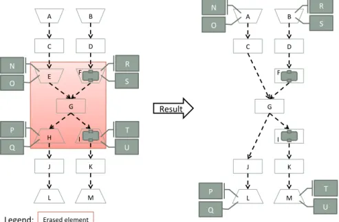
4.20 Merging Example . . . 73
4.21 Erasing - Links . . . 73
4.22 Erasing - Links Bypass . . . 74
4.23 Erasing - Annotations . . . 74
4.24 Erasing - Sub-workflows . . . 75
4.25 Erasing - Link Constraints . . . 75
4.26 Erasing - Example . . . 76
4.27 Discovery Process . . . 77
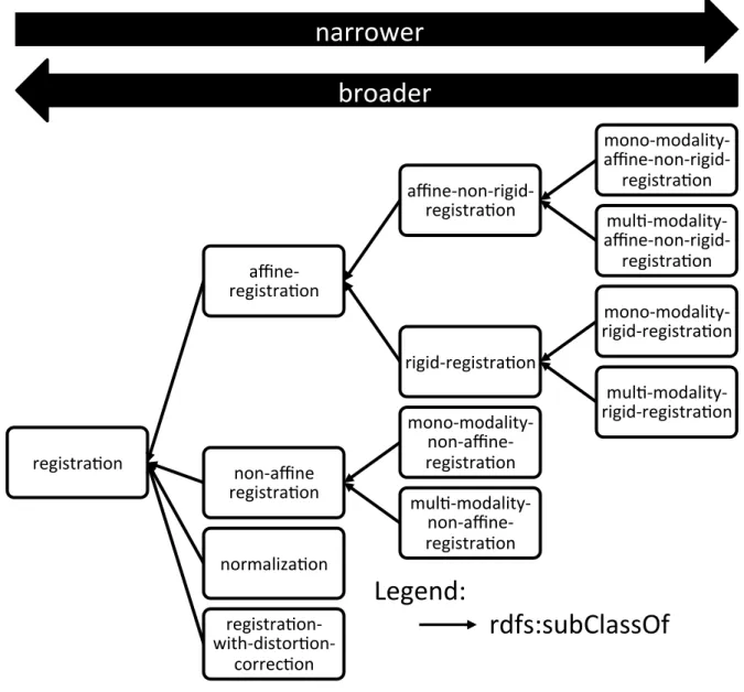
4.28 VIP Ontology (excerpt) - Registration Processes Taxonomy . . . 79
4.29 Matching Query . . . 80
4.30 Composition Process . . . 86
4.31 X→ Y Converter Search Query . . . 92
4.32 Conversion to GWENDIA - Basic Structure . . . 95
4.33 Conversion to GWENDIA - Inputs/Outputs Example . . . 96
4.34 Conversion to GWENDIA - Activities Example . . . 96
4.35 Conversion to GWENDIA - Links Example . . . 98
4.36 Conversion to t2flow - Basic Structure . . . 99
4.37 Conversion to t2flow - Inputs/Outputs Example . . . 100
4.38 Conversion to t2flow - Activities Example . . . 100
4.39 Conversion to t2flow - Links Example . . . 101
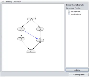
4.40 Conversion to IWIR - Simple Chains Example . . . 102
4.41 Converting Iteration Strategies to IWIR . . . 105
4.42 Classification of the Conversion model transformation . . . 106
5.1 Prototype Architecture . . . 110
5.2 OntoVIP Excerpt - Simulations . . . 112
5.3 OntoVIP Excerpt - Dataset Processing Ascendance . . . 113
5.4 Link to VIP Workflow Designer Screenshot . . . 113
5.5 VIP Workflow Designer Screenshot . . . 113
5.6 FIELD-II - Result Example . . . 115
5.7 FIELD-II - Abstract Workflow (MOTEUR screenshot) . . . 116
5.8 SIMRI - Result Example . . . 117
5.9 SIMRI - Abstract Workflow (MOTEUR screenshot) . . . 117
5.10 SimuBloch - Abstract Workflow (MOTEUR screenshot) . . . 118
5.12 Sindbad - Result Example . . . 118
5.11 Sindbad - Abstract Workflow (MOTEUR screenshot) . . . 119
5.13 SORTEO - Result Example . . . 120
5.14 SORTEO - Abstract Workflow (MOTEUR screenshot) . . . 121
5.15 VIP Simulator Template Conceptual Workflow . . . 122
5.16 FIELD-II Conceptual Workflow . . . 123
5.18 SimuBloch Conceptual Workflow . . . 125
5.19 Sindbad Conceptual Workflow . . . 127
5.20 SORTEO Conceptual Workflow . . . 128
5.21 Simple Sub-workflow Fragment Example . . . 130
5.22 PET 2 Steps Fragment . . . 131
5.23 Split and Merge Fragment - Link-bound . . . 131
5.24 Split and Merge Fragment - Node-bound . . . 132
5.25 Use Case High-level Conceptual Workflow . . . 132
5.26 Mapping Use Case - After Weaving PET 2 Steps . . . 133
5.27 Mapping Use Case - After Weaving SimuBloch . . . 134
5.28 Mapping Use Case - After Weaving (node-bound) Split and Merge . . . 135
5.29 Mapping Use Case - Fixed Split and Merge Steps . . . 136
5.30 Mapped Use Case . . . 136
5.31 Use Case Link Suggestions . . . 138
5.32 Use Case Intermediate Representation . . . 140
5.33 Use Case GWENDIA Conversion Result (MOTEUR screenshot) . . . 141
A.1 Sample ASKALON Workflow . . . 148
A.2 Sample Galaxy Workflow . . . 149
A.3 Galaxy Dummy Cycle Example . . . 150
A.4 Sample GWES Workflow . . . 151
A.5 Sample Kepler Workflow . . . 152
A.6 Sample KNIME workflow . . . 153
A.7 Sample MOTEUR Workflow . . . 154
A.8 Sample Taverna Workflow . . . 157
A.9 Sample Triana Workflow . . . 158
A.10 Sample VisTrails Workflow . . . 159
A.11 VisTrails Dummy Cycle Example . . . 159
A.12 Sample WINGS Workflow . . . 160
A.13 Sample WS-PGRADE Workflow . . . 161
B.1 Conceptual Workflow Meta-model - Conceptual Part . . . 163
B.2 Conceptual Workflow Meta-model - Abstract Part . . . 164
B.3 Conceptual Workflow Meta-model - Semantic Part . . . 164
B.4 Conceptual Workflow Meta-model . . . 165
2.1 Turtle example . . . 35
2.2 N-Triples example . . . 35
2.3 RDF/XML example . . . 36
2.4 RDF/XML example (alternative) . . . 36
2.5 SPARQL SELECT example query . . . 39
2.6 SPARQL CONSTRUCT example query . . . 40
4.1 Fragment to SPARQL Conversion - Fragment Example (abbreviated) . . . 64
4.2 Fragment to SPARQL Conversion - Result Query (abbreviated) . . . 64
4.3 Matching Query (T = target type) . . . 81
4.4 Producer Search Query (T = target type) . . . 89
4.5 Consumer Search Query (T = target type) . . . 90
4.6 X→ Y Converter Search Query . . . 91
4.7 Conversion to GWENDIA - Inputs/Outputs Example . . . 96
4.8 Conversion to GWENDIA - Activities Example . . . 97
4.9 Conversion to GWENDIA - Links Example . . . 98
4.10 Conversion to IWIR - Simple Chains Example . . . 103
C.1 Fragment to SPARQL Conversion - Fragment Example . . . 166
C.2 Fragment to SPARQL Conversion - Result Query . . . 167
D.1 X→ ? → Y Two Converters Chain Query . . . 168
E.1 Conversion to t2flow - Inputs/Outputs Example . . . 170
E.2 Conversion to t2flow - Activities Example . . . 171
E.3 Conversion to t2flow - Links Example . . . 172
F.1 Conversion to IWIR - Flat Inputs Example . . . 176
F.2 Conversion to IWIR - Dot Example . . . 177
First and foremost, I would like to thank my advisor, Johan Montagnat, for your trust, your invaluable advice and your tireless work to help me succeed. Without you, I would have never overcome the beast that my PhD turned into. When you took me under your wing, you warned me that it would be hard - about that you were right - and that I would eventually come to find something amiss with you - about that you were wrong.
My next thanks go to Mireille Blay-Fornarino for treating me like an equal from day one and often seeing more worth in my work than even I would. Your advice was incredibly helpful and your trust was immensely humbling. Thank you for all the time you gave me.
Next I want to bow to the generosity of the other members of my jury. I want to thank Gabriele Pierantoni for being not just a colleague but a friend and for always saying it like it is; Oscar Corcho for showing so much interest in my work even though it pales in comparison to yours in many ways; and Hugues Benoit-Cattin for taking a bit of a leap of faith with me. I am truly grateful for your time and humbled by your trust.
I will never forget the help R´egine Saelens and Gilles Bernot provided me either. You were there for me when I most needed it, the make-or-break moment where, if not for your kindness, I might have given up. Thank you so much.
Next up is my favorite coffee drinking partner, Franck Berthelon. You helped me keep my head clear and my feet on the ground. More than anyone else, you made me feel like I belonged, like I was just another PhD student. I can never thank you enough for that.
I now want to thank Sabine Barrere for the tremendous patience with which you showed me the administrative ropes. You made my life a lot easier and I dare hope I did not make yours too bothersome in return.
Thanks are also due for Michel Buffa, Alban Gaignard, Franck Michel and Olivier Corby. Your patience is superhuman and you helped me a lot more than you probably suspect. Thank you for always taking me seriously.
A bit further away from home, but just as close to heart, I want to thank Tristan Glatard for being an extremely tolerant and insightful colleague; Bernard Gibaud for challenging me to do a better work and giving me precious advice to that end; Kitti Varga for always lifting the mood up no matter the adversity (any project is lucky to have you); Bob Bentley for being such a good sport (how is that for a French?); Silvia Delgado Olabarriaga for talking to me as if we were the same age and of similar accomplishments; and the researchers I had the incredible chance to meet at WORKS’11 after reading their names so often in the litterature, especially Ian Taylor and Ewa Deelman, for being nowhere near as intimidating in person as I had made you up in my head.
I also want to thank Guillaume Husson, Pavel Arapov, Mathieu Acher, Macha Da Costa Barros and Simon Urli for being perfect office-mates. You belied all apprehensions I ever had about office life twenty times over. Anyone sharing an office with any of you is extremely lucky, whether they know it or not.
I did not have the pleasure of sharing an office with Javier Rojas Balderrama, Chris-tian Brel, Fanny Dufoss´e, Filip Krikava, Ketan Maheshwari, Romaric Pighetti or Tram Truong Huu and that is a shame, for I am sure I would have been the luckier one for it. Thanks for being exemplary teammates.
I now want to turn my gratitude towards Loula Fezoui who supported me throughout in so many different ways, up to and including proof-reading just about everything. This thesis would not be anywhere near its current state if it were not for you.
Outside of work, there are too many people I feel grateful towards to list here. Plus, I am afraid I would lose some friends if I tried and inevitably failed to make an exhaustive list. Anyway, if you know me, you probably already know how I feel about you. If, for some reason, you do not, do ask. Come on. I do not bite. :)
And last but not least, I want to thank you for taking the time to read this, whoever you are. Please do take a look at the Glossary too. It’s full of definitions and URLs and funny acronyms, I bet you’ll like it. ;)
And now for something completely different...
It’s not so much about gratitude than simple acknowledgement. Here’s a list of softwares and websites used in the making of this document, besides those mentioned in it:
• BibTeX to generate the bibliography;
• detexify to find some of the LaTeX symbols;
• FreeFormatter.com XML Formatter to indent long XML documents; • Google Scholar to look up most references;
• GraphViz to create some of the figures; • LaTeX to layout the whole document; • MacOS X Preview to crop PDFs; • makeglossaries to generate the glossary;
• Microsoft PowerPoint to create most of the figures; • Prot´eg´e to browse and tinker with ontologies; • subversion to backup the LaTeX source code;
• texmaker and TeXnicCenter to edit the LaTeX source code; and • WordReference to find or check French→English translations.
The following conventions are used throughout the book:
• “Text written in italic between quotes” is either a direct quote from another work or a term commonly found in the litterature.
• T ext written in italic outside quotes is either a latin expression, such as i.e., or a reference to a mathematical or algorithmical element, such as a function.
• Text written in boldface is simply emphasized over the surrounding text.
• Text written in Typewriter style is something technical, such as a literal value, a specific program name or a specific variable.
• Text written in dark blueis either a reference to a specific numbered item (e.g. a section, figure, listing, etc) or a term defined in the glossary.
• Text written in dark blue and boldface is a glossary term emphasized because it is inherent to this work. Most such terms are part of our model and many others are the names of specific processes defined in this work.
• [Text written in green between brackets] is a reference whose details can be found in the bibliography. Outside brackets, green text is reserved for URLs.
“
Text written in rectangles such as this one is a direct quote......AND THIS IS THE AUTHOR OR THE REFERENCE.
Those slightly different rectangles...
...are for equations.
INTRODUCTION
1.1
Simulations
Ever since the conception of computers, scientists have used them to handle part of their scien-tific experiments for many reasons, including:
• performing complex computations that would take too long and be too error-prone for humans to perform;
• manipulating digital data that is captured as-is or converted from analog sources and is then processed by computers; and
• implementing virtual experiments that are used to model reality in order to avoid the costs and risks of practical experiments, to try impractical conditions or to deduce knowl-edge from the model itself.
Scientific experiments that are partially or entirely carried out via computers are called simulations. In the field oflife sciences, they are commonly referred to asin-silico experiments by contrast to other types of experiments, e.g. “in-vivo”, “in-vitro” and “in-situ” experiments.
Completesimulationsvery rarely consist of a simple program. Even in cases where all com-putations are performed inside one executable, there is most often need for data management. Indeed, data must somehow be:
• fetched from where it was captured or generated;
• prepared so that it is compatible with the program(s) using it as input; and
• visualized, transformed or mined so as to provide results to the scientist and/or input data for furthersimulations.
To this day, scientists have chained the various programs composing theirsimulations man-ually or automated them through ad-hoc scripting and generic tools like GNU Make1. Both methods, manual composition and automation via generic tools and script languages, are poor fits forsimulations, for the following reasons:
• the exploratory nature of scientific analysis induces frequent reuse and repurposing, which easily become tedious enough to warrant dedicated systems;
• manysimulationshandle such huge data volume that it is impractical to handle manually and hard to handle reliably via scripting; and
• distributed resources – e.g. databases, data streams, web services, computing grids and clouds – have become an integral part of most simulations and are rather hard to access: scientists find they need to become experts of distributed algorithms and web technologiesin order to leverage the wealth of available distributed resources.
There is thus a practical and growing need for systems dedicated to the automation of simulationsand usage of highly-distributed heterogeneous resources.
1.2
Scientific Workflows
The need to automate the use of highly-distributed heterogeneous resources was first answered in the corporate world – years before the issue was identified as such in the scientific community – by the concept ofworkflow:
“
Definition - WorkflowThe computerized facilitation or automation of a business process, in whole or part.
WORKFLOWMANAGEMENTCOALITION(WFMC)
Applying that definition to scientific processes suggests that any form of automation of a simulationshould qualify as ascientific workflow. In this work, however, we focus on systems built specifically to model, maintain and perform simulations, i.e. what is commonly called scientific workflow frameworks.
Scientific workflow frameworks often target different scientific communities and most of them were developed independently by different teams with different goals; frameworks are therefore plenty and varied (see Section 2.1.4 for an overview). No standard has emerged yet, in the field of scientific workflows, however there are noticeable trends. For instance, most frameworks are compatible withweb services, allowing access to a significant part of the distributed resources available online, and/or provide end-users with drag-and-drop interfaces to composescientific workflowsgraphically, making it easier for beginners to start composing workflows and for everyone to read the workflows authored by others.
One of the most quickly recognizable trends for anyone comparing scientific workflow frameworks is that the vast majority ofscientific workflow models the frameworks rely on – implicitly or explicitly – are based ondirected graphs. That very common choice presents many advantages:
• it is the most straightforward way to represent the order in which tasks must be per-formed and/or how data is to be transferred between tasks;
• it is a graphical representation that is universal enough to be accessible for beginners, who can start composingsimulationtasks without having to learn a language syntax; and • it is especially legible in that it clearly highlights, for the human reader, things about the process that might otherwise be quite hard to detect or evaluate, e.g. complexity, resource consumption, bottlenecks, loops and unreachable code.
For all those reasons, the vast majority of systems opted for directed graphs despite their disadvantages, most notably the lack of scalability: hugegraphsare hard to layout, to read and to process. In order to have a basis of comparison and cater to most systems, we have chosen to focus onscientific workflow frameworkswhose models are based ondirected graphs– though in some cases the user interfaces might not expose that fact.
1.3
Challenges
The main goal ofscientific workflowsis, by definition, to automatesimulations. Interestingly though,scientific workflowsare increasingly used by scientists to formalize and share not only the results of their experiments, but also the scientific processes that produced them. As that usage spreads, so does the need for other features.
For instance, the need for provenance – to relate data with theworkflowand parameters that produced it, so as to facilitate reuse and peer validation – sparked a series of four Provenance Challenges2which led to the definition of theOpen Provenance Model (OPM)and recently the
World Wide Web Consortium (W3C)standardPROV, which are widely regarded as standards for provenance modeling and sharing. Another good example of a hot topic is preservation – to run ascientific workflow, and thus run all of its components and access all the necessary data, years after its design and publication. That growing concern in the field is the main goal of the Wf4Ever project [Belhajjame 12].
The present work focuses on three key aspects ofscientific workflows:
• accessibility, i.e. the ease with which domain scientists can read workflowscreated by other people or create their own;
• reuse, i.e. the ease with which users can useworkflowscreated by other people for the same or different goals (a case referred to as repurposing); and
• comparison, i.e. the ease with which someone can compare different scientific work-flowsor differentscientific workflow frameworks.
Despite laudable efforts to make scientific workflowsaccessible and reusable, notably via easy-to-useGraphical User Interfaces (GUIs), it is widely recognized that most existing scien-tific workflow modelsremain complex to use for scientists who are not experts of distributed algorithms[Gil 07,McPhillips 09]. We argue that the main factors exacerbating that complex-ity are (i) the fairly low level of abstraction of most existing scientific workflow modelsand (ii) the entanglement of different types of concerns which adversely affects legibility.
Both factors stem directly from scientific workflow models. Indeed, they constrain the range of abstraction in whichscientific workflowscan be modeled and determine whether and how different types of concerns may be separated. Comparison is also hindered by the variety of models, absence of standard and difficulty of converting from a model to another. Hence the goal of this work:
Create a newscientific workflow modelto improve accessibility, ease reuse and allow comparison.
GOAL
1.4
Abstraction Levels
Scientific workflows are used to formally modelsimulations so they can be performed auto-matically on computing infrastructures. There is an obvious gap between the level at which simulationsare conceived (i.e. the scientific domain(s) of the end user) and that of enactment.
The vast majority ofscientific workflow modelslie between those two levels: more techni-cal than thesimulationsthey model, so that they can be executed, yet shielding the user from much of the complexity ofdistributed algorithms,web technologiesandDistributed Computing Infrastructures (DCIs).
On the one hand, it is relatively common to call the level of abstraction of most scientific workflowstheAbstract Leveland that of enactment theConcrete Level[Yu 05]. On the other hand, to the best of our knowledge, there is no consensus as of yet for the name of the highest level of abstraction (i.e. the level of thesimulationsthemselves): we call itConceptual Level to contrast it with theAbstract Level, but it is sometimes called “Abstract”, e.g. in [Garijo 11], and hence might confuse the unsuspecting reader.
Given the definitions we just established and since our goal is to improve accessibility, we need ourscientific workflow modelto be as close as possible to the scientific domain(s) of the end users and therefore to lie at theConceptual Level.
Create a newscientific workflow modelat theConceptual Level. METHOD(PART 1OF 4)
End$user)
Scien-fic)
Workflow)
Framework)
Compu-ng)
Infrastructure)
1 2 3Conceptual)
Level)(CIM))
Abstract)
Level)(PIM))
Concrete)
Level)(PSM))
A B S T R A C T I O NMost scientific workflow frameworksinvite users to work directly at the abstraction level of their scientific workflow model, bypassing the transformation from Conceptual Level to Abstract Levelin the sense that thesimulationitself is never formally defined and thus never actually transformed. However, the transformation from Abstract Level to Concrete Level can never be bypassed, since automation (and thus execution) is the main goal of scientific workflows. In most cases, that transformation is performed automatically by the scientific workflow framework.
We argue that the three levels of abstraction we just defined align very well with those of theModel Driven Architecture (MDA), as shown onFigure 1.1:
• TheConcrete Level is that of the execution ofscientific workflows by anenactor over aDCI. At this level, models are tightly-coupled with the infrastructure and are therefore referred to asPlatform-Specific Models (PSMs)in theMDA.
• The Abstract Level is that of most scientific workflow models, ready to be automati-cally compiled or directly interpreted, but not entirely bound to specific resources and retaining some flexibility. Models at this level aim to be independent from computing infrastructures and are referred to asPlatform-Independent Models (PIMs)in theMDA. • The Conceptual Level is the one at which scientists conceive their scientific
experi-ments in a vocabulary that is familiar to them. Conceptual models are referred to as Computation-Independent Models (CIMs) in theMDA, since they remain independent from how the system is or will be implemented. The distinction betweenCIMandPIM is much clearer in theMDAthan it is in the field ofscientific workflows, but few works have touched upon the transition from one to the other [Singh 10].
Theoretically, scientists can: (i) pick the scientific workflow framework which best suits their needs among a huge selection, (ii) design theirsimulationsdirectly in the associated sci-entific workflow modeland (iii) run their experiments on compatibleDCIs.
However, in practice: (i) there are few surveys for users to compare existing systems and pick the most suitable [Yu 05,Taylor 07a,Barker 08,Curcin 08], (ii) designing at theAbstract Levelrequires technical know-how and knowledge about the target infrastructure, thus raising the entry barrier for scientists of all domains but that ofscientific workflowsand (iii)scientific workflow frameworks tend to be tied to their target DCIs enough to warrant multi-workflow systems interoperability projects likeSHIWA[Krefting 11].
Hence the need not only to formalizesimulationsat theConceptual Levelbut to develop a process to help users transform those representations down to theAbstract Level.
Develop a computer-assistedTransformation Processfrom the Conceptual Levelto theAbstract Level.
METHOD(PART 2OF 4)
There are three reasons why the Transformation Process must remain in our scientific workflow modelas long as possible.
Firstly, without a closed-world assumption and a curated base of resources, the process can-not be fully automated. For one thing, it is impossible to guarantee that the resources needed to implement the user goals exist or can be identified as such. Since theTransformation Process requires user intervention, it would make sense not to jump from thescientific workflow model thesimulationis designed in to a distinct model right at the start of the process.
Secondly, the frontier between Conceptual LevelandAbstract Levelis somewhat in the eye of the beholder: what passes for technicalities for one scientist might be core domain concerns for another one. It is therefore useful to cater to multiple levels of abstractions inside the samescientific workflow model, as has been recognized in the literature:
“
Workflow representations must accommodate scientific process de-scriptions at multiple levels. For instance, domain scientists might want a sophisticated graphical interface for composing relatively high-level sci-entific or mathematical steps, whereas the use of a workflow language and detailed specifications of data movement and job execution steps might con-cern computer scientists. To link these views and provide needed capabil-ities, workflow representations must include rich descriptions that spanabstraction levels and include models of how to map between them. [...]
Other important and necessary dimensions of abstraction are experiment-critical versus non-experiment-experiment-critical representations, where the former refers to scientific issues and the latter is more concerned with operational matters.
[GIL 07]
Thirdly, a conceptual scientific workflow model sufficiently independent from the lower abstract layer might serve as a basis of comparison between existingscientific workflow frame-works. One way to increase independence is to avoid picking a specific target abstractscientific workflow modeland instead wait until the very last moment to delegate.
For those three reasons, theTransformation Processis divided in two distinct steps: • Mappingis computer-assisted and transforms thescientific workflowfrom the
Concep-tual Levelto anIntermediate Representationlying at theAbstract Level.
• Conversionis fully automated and converts theIntermediate Representationto a target language, so as to delegate to an existingscientific workflow framework.
And this split sparks the following need:
Extend thescientific workflow modelwith elements of theAbstract Level to modelIntermediate Representations.
METHOD(PART 3OF 4)
1.5
Entanglement of Concerns
Each phase of ascientific workflowlifecycle comes with its share of concerns, as summarized on Figure 1.2: (i) during Design, the simulation itself caters only to domain concerns, i.e. concerns pertaining to the scientific domain of the end-user; (ii) during Implementation, the scientific workflow must somehow fulfill all technical concerns in order to be executable; and (iii) during Execution, all manners of non-functional concerns become relevant, e.g. performance, reliability andprovenancecapture.
Design) Concerns:) • Domain Implementa-on) Concerns:) • Domain) • Technical Execu-on) Concerns:) • Domain) • Technical) • Non.func1onal
Figure 1.2: Scientific Workflow Concerns and Lifecycle
As an illustration of just how tangled those concerns can become,Figure 1.3shows a Tav-erna[Missier 10a]workflowpublished by Paul Fisher on myExperiment3where we categorized each node as either domain, technical or non-functional based on its name.
Legend:)
)))))))))))))))Domain)
)))))))))))))))Technical)
)))))))))))))))Non$func-onal)
Figure 1.3: Scientific Workflow Concerns Entanglement Example
It is fairly easy to see how indiscriminately mixing concern types can lead to much confu-sion when reading scientific workflowsand much hardship when trying to maintain or repur-pose them. The need to separate concerns inscientific workflows, not just inside one system but via multiple complementary ones, has already been expressed in the literature as such:
“
We also argue that in order to address all the important issues such as scalability, reliability, scheduling and monitoring, data management, col-laboration, workflow provenance, and workflow evolution, one systemcan-not fit all needs. A structured infrastructure that separates the concerns of
workflow specification, scheduling, execution etc, yet is organized on top of components that specialize on one or more of the areas would be more appropriate.
[ZHAO 08]
We thus argue that for a conceptualscientific workflow modelto be truly effective, it must not only cater to the Conceptual Level of abstraction, but also allow proper Separation of Concerns (SoC), by allowing users to define concerns of different types separately from the baseworkflowthey will be woven into.
Develop technologies to weave different types of concerns intoscientific workflows. METHOD (PART 4OF 4)
1.6
Goals
Let us recap the goals of this work. In an effort to improve the accessibility ofscientific work-flows, we aim to:
1. create ascientific workflow modelat theConceptual Level;
2. extend the model withAbstract Elementsto modelIntermediate Representations; 3. develop technologies to assist theMappingphase of theTransformation Process, from
a high-levelworkflowto anIntermediate Representation;
4. develop technologies to automate theConversionphase from an Intermediate Repre-sentationto a targetscientific workflow model; and
5. develop technologies to weave concerns intoscientific workflowsto ensure properSoC. In Chapter 2, we present the state of the art ofscientific workflow models as well as the domains our approach meets: model-driven engineering, separation of concerns and semantic knowledge engineering. We then present ourscientific workflow modelin Chapter 3 and the tools we provide - to transformConceptual Workflowsand delegate them to existing frame-works, includingWeavingto improveSoC- inChapter 4. Chapter 5validates our contributions by applying them to real-life examples. Preliminary work was published in [Cerezo 11] and an earlier version of our contributions was published in [Cerezo 13].
The objectives of this work are the design of a scientific workflow model encompassing conceptual and abstract levels of abstraction as well as the development of a transformation process supporting proper Separation of Concerns, in order to improve accessibility, ease reuse and allow compar-ison of scientific workflows.
STATE OF THE ART
Long before they were used to model and automate simulations, workflows were defined, formalized and used in the industry for business processes. The research field of business workflowsgrew years before that ofscientific workflows[Georgakopoulos 95] and has known many fundamental works and standardization initiatives such as the Workflow Patterns Initia-tive [Van Der Aalst 03].
The frontier between the two types of workflows, i.e. business workflows versus scien-tific workflows, is somewhat blurry and subjective. Nothing prevents a user from using a business workflow framework to model and perform a scientific experiment or a scientific workflow framework to capture and automate a business process. There are notably many efforts to use the de facto standard business workflow language Business Process Execution Language (BPEL)directly or adapt it forsimulations[Emmerich 05,Akram 06,Slominski 07,
Wassermann 07,Sonntag 13].
The differences betweenbusiness workflowsandscientific workflowspertain essentially to priorities and context, as detailed in [Barga 07] as well as in [Sonntag 10,G¨orlach 11], notably:
• The need for security and privacy, extremely important in a business context, is much less prevalent in the scientific community, where peer validation and collaboration are common goals that imply sharing, reuse and repurposing.
• The need for integrity and reliability is a central aspect of business services and thus a top priority forbusiness workflows, but the exploratory nature of research makes flexi-bility a much greater priority forscientific workflows.
• Many business contexts require the fine-grained control and expressivity provided by control-driven models. However, scientific data is most often the first-class citizen of a simulation, which makes data-driven models and hybrid models better fits for most scientific workflows. In particular, data-driven and hybrid models can leverage data par-allelism implicitly [Montagnat 09], which is crucial to many data- and compute-intensive simulations. The distinction between the three types ofscientific workflow modelsis ex-plained inSection 2.1.2.3.
• On the one hand,business workflowdesigners often face either (i) a lack of suitable can-didateweb servicesto perform a step in their process or (ii) a wealth of functionally close candidates which need to be differentiated through considerations ofQuality of Service (QoS) and cost. On the other hand, scientific workflowdesigners often start modeling their simulations with the main services/programs already determined and generally find very few viable alternatives, since different candidates for a scientific process step often pertain to substantially different scientific approaches.
In this work, we focus on scientific workflows and scientific workflow models, analyzed and overviewed inSection 2.1, and notbusiness workflowsand their associated models. Ele-vating the abstraction level greatly improves accessibility but is not sufficient to ensure proper Separation of Concerns (SoC): that entails specific efforts which are somewhat transversal to abstraction levels, such as those described in Section 2.2. However, to be truly useful, high-level models and properSoCmust fit into a broader process to assistscientific workflowdesign. We chose to rely on an existing software development paradigm: Model Driven Engineering (MDE)described inSection 2.3. Section 2.4outlines existing technologies to capture and lever-age domain knowledge and know-how in order to assist the model transformations involved in our approach.
2.1
Scientific Workflow Models
In this overview of existingscientific workflow frameworks, we will analyze some of the most used systems along three dimensions: Interface, i.e. how users can createworkflows and/or execute them; Model, i.e. the nature of thescientific workflow modelused explicitly or implic-itly; and Abstraction Level, i.e. where the system falls on the scale we defined inSection 1.4 (Conceptual, Abstract and Concrete).
2.1.1
Interface
There are plenty of ways for users to interact with scientific workflow frameworks. We will focus here on the following:
• Application Programming Interfaces (APIs) are protocols specifying how other pro-grams may interact with the system. APIs let users generate, execute and/or monitor scientific workflowsfrom inside other programs.
• Command-line interfaces let users executescientific workflows directly from the com-mand line. One of the advantages of doing so is that it greatly facilitates runningscientific workflowson remote infrastructures.
• Graphical User Interfaces (GUIs) let users create and modify scientific workflows graphically. They often also provide a visual way to monitor their execution.
• Dedicated file formats were created and documented not just internally inside the frame-work development team, but for end-users to create and edit theirscientific workflowsin a format directly understandable by the framework.
• Portals target domain scientists and hide most of the complexity and technical details of scientific workflows. They even often hide the underlyingscientific workflowsentirely, focusing instead on input data and the scientific method in use.
• Scripting languages differ from dedicated file formats in that they are much more con-cise and are interpreted to generate the usually verbose executable format handled di-rectly by theenactor.
• Web servicesare a particular kind ofAPImeant to be used over the internet. We consider that they are available as an interface to a framework if said framework generates them automatically for theenactorand/orscientific workflowinstances.
2.1.2
Model
Directed graphslend themselves especially well to the modeling of processes, with nodes rep-resenting steps or locations and edges reprep-resenting dependencies or transitions. Though there may be scientific workflow models wholly incompatible with directed graphs, most systems have either adopted them directly or adopted a compatible model.
We focus here ongraph-based models so as to ensure some measure of comparability. We further distinguish the types ofdirected graphsused in each model based on the class ofgraphs used and the nature of the edges therein.
2.1.2.1 Graph Type
Directed Acyclic Graphs Plenty of scientific workflow frameworks (for instance Taverna [Missier 10a], cf. Section A.11) adopt Directed Acyclic Graphs (DAGs) as their core model for two main reasons: it is the closest representation to the way tasks are actually executed, no matter the targetDistributed Computing Infrastructure (DCI); and it is very straightforward for data analysis pipelines, which represent a big part ofscientific workflows.
Directed Cyclic Graphs Manyscientific workflow frameworks(e.g. Kepler[Lud¨ascher 06],
cf. Section A.5) opt instead forDirected Cyclic Graphs (DCGs)as their core model and thus allow loops to be modelled as such, instead of through constructs or dedicated activities.
Petri Nets Several systems (e.g. GWES[Neubauer 05], cf. Section A.3) have adoptedpetri netsas their core model, because it is a mathematical model designed specifically for distributed systems and it is already mastered by plenty of scientists who are eager to runsimulationson DCIs.
2.1.2.2 Node Type
Nodes in graph-based scientific workflow models most often represent processing steps, i.e. either a simple invocation of a program, script orweb serviceor a call to a sub-process or some abstraction thereof. Petri netsare an exception to that rule: half their nodes represent locations and the other half transitions between the locations.
2.1.2.3 Edge Type
Edges in graph-basedscientific workflow modelsdenote flow between the nodes: they specify how information and execution must be handled by the enactor. It is common practice to classify graph-basedscientific workflow modelsinto three categories according to the type of flow their edges represent [Shields 07,Deelman 09]:
• if all edges represent data flow, i.e. data transferring from a processor or location to the next, they aredata-driven models;
• if all edges represent control flow, i.e. ordering constraints specifying that the target activity must run after the source activity, they arecontrol-driven models; and
Data-driven Models Edges indata-driven models(for instanceTriana[Taylor 07b], cf. Sec-tion A.12) represent data flow between otherwise independent processing units. Perfect for digital processing pipelines and other streamlined processes, those models are, at first glance, the easiest to read and write.
However, their most useful feature - as far asscientific workflowsare concerned - is implicit parallelism: on the one hand, processing units can run as soon as input data and the necessary computing resources are available, on the other hand, data sets can be split and dispatched to parallel computing resources automatically. As a result, those models shift the burden of planning asynchronous execution from theworkflowdesigner to theenactor.
Unfortunately, elementary control constructs, such as conditionals and loops, are necessary for all but the simplest and most straightforward analysis pipelines. As a result, either data-driven modelsare extended with those constructs and become hybrid modelsor they emulate the corresponding behaviors, as illustrated onFigure 2.1:
• Straightforward ordering constraints can be implemented through dummy data tokens representing the control transmitted from the source to the target activity.
• More sophisticated control constructs must be implemented via dedicated activities han-dling them transparently from the viewpoint of thedata-driven model.
Dedicated activities used to implement control structures tend to diminish the overall legi-bility ofworkflowsin that knowledge of theworkflowlanguage itself is not enough: the reader has to identify every dedicated activity and decipher its meaning to understand the workflow logic. In practice, there is also a matter of portability with those activities, as they are often implemented via ad-hoc scripting and may well not run as-is in a different framework.
Ac#vity(B( Ac#vity(A( Ac#vity(C( Ac#vity(D( Ac#vity(B( Ac#vity(A( Ac#vity(C( Ac#vity(D( Condi#on( Handler( Legend:( (((((((((((((((Flow((control(on(the(le;,(data(on(the(right)( (((((((((((((((Data(port( (((((((((((((((Dummy(data(port( ControlAdriven( DataAdriven( IF(condi#on( ELSE(
Control-driven Models Control-driven models (e.g. ASKALON [Fahringer 07], cf. Sec-tion A.1) andImperative Programming Languages (IPLs) follow the same fundamental prin-ciple: control is transferred from an operator to the next according to control constructs such as sequences, loops and conditionals. Because scientific workflows are meant to carry out simulations, unlike general-purposeIPLs,control-driven models:
• most often support graphical composition;
• aim at the best trade-off between expressivity and ease-of-use; and
• explicitly target parallel execution, notably by automatically handling the fine-grained elements thereof, such as messages and semaphores.
IPLsandcontrol-driven modelsalso differ by their respective abstraction levels: mostIPLs are hardware-centric and deal with low-level operations such as variable assignment and mem-ory allocation, but such tight coupling with the hardware would make scientific workflows unusable on heterogeneous DCIs. Therefore, control-driven scientific workflows deal with high-level operators, such asweb servicesand grid jobs, and high-level control constructs that encapsulate complex transfer protocols between those operators.
Data is the first-class citizen in mostsimulations, yet it must be handled explicitly in control-driven models, which makes them less popular within the scientific community than within the business one. Incontrol-driven models, data dependencies are modeled through intermediate activities that explicitly perform file transfers and handle synchronization from producer to consumer activity, as shown onFigure 2.2.
Legend:(
(((((((((((((((Flow((data(on(the(le;,(control(on(the(right)(
(((((((((((((((Data(port(
Ac#vity(B(
Ac#vity(A(
DataAdriven(
ControlAdriven(
Ac#vity(B(
Ac#vity(A(
Data(
Handler(
Hybrid Models The current tendency in the field of scientific workflows is to buildhybrid models; most often data-driven models that are extended with select control constructs (e.g. MOTEUR[Glatard 08], cf.Section A.7).
“
It is clear that both control and data flow techniques are needed for scientific workflow languages. [...] Simple hybrid models with limited con-trol constructs and support for data flow appear to stand the best chance of being interoperable with the most tools and frameworks but still contain enough functionality to be able to represent real scientific applications.[DEELMAN 09]
Note that emulating control constructs in adata-driven modelthrough dedicated activities, does not make the model itself hybrid. Indeed, the semantics of the model are unchanged and the control constructs are hidden from theenactor.
2.1.3
Abstraction Level
As stated inSection 1.4, most existingscientific workflow frameworkslie roughly at the Ab-stract Level. They are not however all at exactly the same level of abAb-straction.
Plenty of factors may contribute to elevate the abstraction level of a scientific workflow framework. We will focus on the following four criteria (the convention is that the level of abstraction is higher if the answers are positive than otherwise):
• Annotations: Can the scientific workflowsand/or their components be annotated with Semantic Annotations? With curated keywords? With informal tags?
• Composition: Does the system automatically compose scientific workflows? Does it provide the user with suggestions of edges or nodes? Does it check existing edges for potential mismatches?
• Flexibility: Is there any structural flexibility in thescientific workflow model? Can the same scientific workflow instance represent or lead to (via generation/transformation) structurally different processes (e.g. a sequence of 3 tasks vs. 4 parallel tasks)? Is there flexibility in the data representation (e.g. multiple files can be represented by a single input parameter)?
• Indirection: Is there indirection between the specification of a task and the technical execution thereof? Can a given activity represent multipleweb services? Multiple pro-grams? Multiple processing units?
2.1.4
Comparison Matrix
Table 2.1 compares 15 of the most well-known scientific workflow frameworksalong the di-mensions described in the three previous sections. Details of each system can be found in Appendix A.
2.1. SCIENTIFIC W ORKFLO W MODELS CHAPTER 2. ST A TE OF THE
Table 2.1: Scientific Workflow Models - Comparison Matrix
Framework/Language Interface Model Abstraction Level
Annotations Composition Flexibility Indirection
ASKALON/AGWL F, G Control-driven DCG ❴ ✝ ✫ ✫
Galaxy G, P Data-driven DCG ❱ ✫ ✫ ❴
GWES/GWorkflowDL C, F, G, P, W Petri Net ❱ ✫ ✫ ❱
Java CoG Kit/Karajan C, F, G, S, W Control-driven DCG ✫ ✝ ✫ ✝
Kepler/MoML C, G Hybrid DCG ❱ ❴ ❴ ✫
KNIME A, G, P Hybrid DAG ❴ ✫ ✫ ✫
MOTEUR/GWENDIA F, G, S, W Hybrid DCG ❴ ❴ ✫ ❴
Pegasus/DAX A, C, F Petri Net ✫ ✫ ✫ ❴
SHIWA/IWIR C, F Control-driven DAG ✫ ✫ ✫ ✫
Swift S Hybrid DCG ✫ ✫ ❴ ✫
Taverna/SCUFL C, G Data-driven DAG ❴ ❴ ✫ ❴
Triana G Data-driven DCG ✫ ✫ ✫ ✫
VisTrails G Data-driven DCG ❱ ✝ ✫ ✫
WINGS G Petri net ❱ ❱ ✫ ❱
WS-PGRADE G, P, W Data-driven DAG ✫ ✫ ✫ ❱
Interface: A:API, C: Command-line, F: Files (dedicated format), G:GUI, P: Portal, S: Scripting language, W:Web service
Abstraction Level Feature:❱: Supported,❴: Marginally present,✫: Essentially absent,✝: Third-party project(s)
2.1.5
Discussion
Though the previous section only describes some of the most well-knownscientific workflow frameworks, it does give enough of an overview of the field to draw some conclusions.
2.1.5.1 System
There are enoughscientific workflow frameworksavailable already and thus very little incen-tive to create yet another full-fledged framework, catering toscientific workflowsfrom design to enactment. Instead, it seems more sensible to build either libraries (e.g. for provenance cap-ture) for existing frameworks to rely on or stand-alone systems lying upstream (e.g. for design or sharing) or downstream (e.g. for enactment) from existing frameworks.
Since our aim is to elevate the abstraction level and assist the design ofscientific workflows, we intend to build a stand-alone design system upstream from existing frameworks, i.e. a program focused solely onscientific workflowsdesign and delegating management, enactment and so on to existing systems.
2.1.5.2 Model
Existing scientific workflow models vary widely and each solution presents advantages and flaws. For instance,DAGsare the most straightforward graph type and the easiest to check for errors, DCGs are more expressive but a little harder to check since they allow loops, endless loops included, andpetri netsare already well-known to many scientific communities but are somewhat more complex to approach for complete beginners.
The trade-off between expressivity and accessibility is a complex one. Often, the most expressive models are the hardest to apprehend, but if a model is too simplistic, it will regularly require convoluted schemes. For instance, loops are commonly used in simulationsand their implementation with data-driven DAGs, via dedicated activities, is uneasy and inconsistent (between different frameworks) enough to defeat the purpose of accessibility.
Our objective is to allow most scientists to model their simulationsat the highest level of abstraction in as straightforward a way as possible. The best pick thus seems to be a nested directed cyclic graphwhich is mainly data-driven and hybridized with control constructs.
2.1.5.3 Abstraction Level
Though a lot of effort has been put into increasing accessibility to scientific workflow frame-worksthrough easy-to-use interfaces and scientific portals which hide the underlyingscientific workflows, the actual abstraction level of most existing scientific workflow models is pretty low.
We identified four features as key to elevating the abstraction level. Annotations and indi-rection are slowly becoming staples in the field and automated composition is certainly a hot topic. The new frontier is now the structural flexibility: even WINGS[Gil 11b], whose level of abstraction is clearly the highest in the field as of this writing, presents no such flexibility whatsoever.
That lack may be a legacy ofbusiness workflows. Indeed, whilebusiness processesevolve with time, they are nowhere near as variable as simulations, given the exploratory nature of science. It thus may seem reasonable to think of two structurally differentbusiness workflows as different and independent workflows, unlike scientific workflows where a given scientific protocol could and often is implemented in ways that significantly differ structurally.
For instance, theVirtual Imaging Platform (VIP), cf. Section 5.2, whose aim is to interop-erate medical imaging models and simulators seminally included four simulators, and although the same general template holds true for all four simulators - and most simulators that have been added since or will be added in the future - theworkflows, elements and structure, vary widely.
We argue that ascientific workflow modelthat would allow the modeling of allVIP simu-lators via a commonscientific workflow, at the level of abstraction at which they are identical, would be beneficial in that it would ease the understanding of those applications as well as their comparison.
2.2
Separation of Concerns
Ensuring proper SoC is one of our goals, as stated in Section 1.6, and none of the systems analyzed in Section 2.1 achieve that particular goal. It is no surprise, given that structural flexibility is key to properSoCand it is hardly supported in existingscientific workflow models.
2.2.1
Paradigm
The notion ofSoCwas first introduced by E.W. Dijkstra:
“
Let me try to explain to you, what to my taste is characteristic for all intelligent thinking. It is, that one is willing to study in depth an aspect of one’s subject matter in isolation for the sake of its own consistency, all the time knowing that one is occupying oneself only with one of the aspects. We know that a program must be correct and we can study it from that viewpoint only; we also know that it should be efficient and we can study its efficiency on another day, so to speak. In another mood we may ask ourselves whether, and if so: why, the program is desirable. But nothing is gained – on the contrary! – by tackling these various aspects simultaneously. It is what I sometimes have called “the separation of concerns”, which, even if not perfectly possible, is yet the only available technique for effective ordering of one’s thoughts, that I know of. This is what I mean by ”focusing one’s attention upon some aspect”: it does not mean ignoring the other aspects, it is just doing justice to the fact that from this aspect’s point of view, the other is irrelevant. It is being one- and multiple-track minded simultaneously.[DIJKSTRA82]
As the name and quote indicate,SoCis the name of a software design paradigm which can be described as such: programs often cater to wildly different (and sometimes contradictory) concerns and – in order to ease understanding, reuse, repurposing and modification – those concerns should be analyzed separately rather than mingled indiscriminately. This paradigm became more prominent over the last two decades [H¨ursch 95].
2.2.2
Main general approaches
It is sometimes possible to separate concerns with the traditional techniques of encapsulation and modularization, but many typical concerns defy those techniques [Aldrich 00]. There is thus a need for software design approaches specifically dedicated toSoC. One of the earliest of such approaches focused on the notion of subjectivity and is subsequently called Subject-Oriented Programming (SOP).
2.2.2.1 Subject-Oriented Programming
At the basis ofSOPis the notion that not every feature and function of an object is inherent to that object. In the now classical example of the tree, which to the best of our knowledge was introduced in the fundamental work [Harrison 93], it is easy to see that things like height and photosynthesis are intrinsic to the tree itself, whereas things like food value for birds and time to cut for lumberjacks are extrinsic.
An object can thus be built by composing “subjects”: sets of fields and methods that are relevant to a specific application. This approach separates concerns of different applications, but it does so in a quite static and somewhat restrictive way.
In real life, the different ways an object is perceived based on beholder are indeed subjective views and the different ways objects behave and interact based on context are the “roles” they play. Hence the notion ofRole-Oriented Programming (ROP).
2.2.2.2 Role-Oriented Programming
It is somewhat hard to track down the notion ofROP. It seems many concurrent works coined the term simultaneously [Belakhdar 96,Kristensen 96,Reenskaug 96].
ThoughROPhas been suggested in a more general context [Kristensen 96,Reenskaug 96,
Demsky 02], it has been especially adopted in the field of multi-agent systems [Cabri 04]. In-deed, the notion of “role” might well be a more natural fit than that of function, when consid-ering software agents, given that agent design focuses on autonomy and collaboration.
There are various ways to implement ROP. One of the most well-known frameworks is ROPE [Becht 99], which defines a domain-specific language and associated transformation process to design “cooperation processes”.
AlthoughROP is an obvious good fit to model multi-agent systems, it does not handle all kinds of concerns equally well:
• functional concerns describe the system’s basic functionality, e.g. what it is meant to do and how it does it;
• non-functional concerns, by contrast, cater to preoccupations and properties outside the basic functionality of the system, e.g. logging might be a very important part of a program’s lifecycle, but, unless the program is a logging middleware, it is not a functional concern; and
• cross-cutting concerns are special non-functional concerns that significantly impact the structure of the process and/or are replicated in multiple points in the process and thus cannot be properly separated via modularization and encapsulation.
SOP andROP divide objects along component lines that run parallel to traditional object classes and are as limited as traditional object-oriented programming when it comes to captur-ing cross-cuttcaptur-ing concerns. For instance, whether a Logger is implemented as a class, subject or role does not change the complexity of tying it to every part of the system that must be logged. Hence the need for the more flexible notion of “aspect”:
“
The basis of the problem is that some kinds of behavior or function-ality cross cut or are orthogonal to classes or components; these kinds of behavior appear in many components and are not easily modularized to a separate class. Aspects cut across or cross-cut the units of a systems func-tional decomposition (objects).[KENDALL 99]
2.2.2.3 Aspect-Oriented Programming
Aspect-Oriented Programming (AOP)was conceived to tackle – and focuses on the issue – of cross-cutting concerns [Kiczales 97]. The aspect-oriented approach is to define cross-cutting concerns separately from the base process they are woven in and to weave them automatically. This is achieved by:
• the definition of a “base process” catering only to the functional aspects of the process; • the declaration of “join points”, i.e. precise locations in the base process where
cross-cutting concerns might be woven;
• the specification of “aspects” composed of “advice”, which define the additional behavior needed to fulfill the cross-cutting concern, and “pointcuts”, which detect matching join points to determine where the aspect must be woven into the base process; and
• the use of an automated “Weaver” which will modify the base process with all the pro-vided aspects.
The most well-known implementation ofAOPis arguably AspectJ [Kiczales 01]. It is based on the Eclipse1 framework and extends Java with aspects that can either use the typical combi-nation of advice and pointcuts or directly and namely add methods, fields or interfaces to exist-ing classes. It inspired similar extensions for a variety of languages, e.g. AspectC [Coady 01] for C, AspectC++ [Spinczyk 02] for C++, AspectS [Hirschfeld 03] for Smalltalk and many li-braries2 for the .NET framework. There are also language-independentAOPframeworks like
Compose* [De Roo 08].
There are other Java libraries and frameworks for AOPin Java, notably JAC [Pawlak 01] which is a framework written in pure Java: it is less flexible than AspectJ in that programs must be built from the ground up following its logic and structure, but it is also more flexible in that aspects can be woven or unwoven at runtime.
1Eclipse:http://www.eclipse.org
Using AOPdoes not automatically imply using dedicated libraries and frameworks: AOP features have been incorporated into some languages like Perl3 and are currently being incor-porated into others like Ada4.
One of the flaws ofAOPis that the end result of weaving aspects into a base process tends to depend heavily on the order in which the aspects are woven. ADORE [Mosser 12] solves that problem by relying on logical foundations that allow interference detection and by mixing AOPprinciples with those ofFeature-Oriented Programming (FOP).
2.2.2.4 Feature-Oriented Programming
Object-Oriented Programming, by focusing on the nature of objects and how they can be clas-sified rather than on functionalities, tends to heavily limit feature composition. For instance, many Object-Oriented Programming languages do not allow multiple inheritance and thus something as simple as a square having all the features of both rectangles and rhombuses is hard to model. There is also a semantic problem in that saying that objects of type A share functionalities with objects of type B does not necessarily mean that they are similar in na-ture. Projects thus often end up with plenty of generic classes such as “Sortable” which do not describe the objects therein as much as what they can do or what can be done with them.
The paradigm ofFOPaims to remedy that problem and is a bit reminiscent of iterative and incremental development: a program is made by stacking an ordered composition of “features” [Prehofer 93] which are formally defined and relatively small sets of functionalities. For that process to work out automatically, features are defined by how a program must be modified to acquire the associated functionalities. It is then a matter of applying all transformations sequentially, different composition orders generally resulting in different end programs.
Theoretically, the number of possible feature compositions grows exponentially with the number of available features. In practice though, not all feature compositions are viable or de-sirable. Inspired by industrial product lining,Software Product Lines (SPLs)analyze and define the exact set of viable and desirable feature compositions via “feature models” [Clements 01].
Smartphone(
Screen(
Keyboard( Camera( Network(
OneAPoint( Mul#APoint( Touch(
Virtual( Physical( Front( Rear( 2G( 3G( 4G(
Legend:( (Mandatory( (Op#onal( (XOR(Alterna#ve( (OR(Alterna#ve( Virtual(implies(Touch
Figure 2.3: Feature Diagram Example
3Perl Aspect module:http://search.cpan.org/dist/Aspect/lib/Aspect.pm 4Ada 2012 Rationale:http://www.ada-auth.org/standards/rationale12.html