HAL Id: hal-00780877
https://hal.archives-ouvertes.fr/hal-00780877
Submitted on 24 Jan 2013
HAL is a multi-disciplinary open access archive for the deposit and dissemination of sci-entific research documents, whether they are pub-lished or not. The documents may come from teaching and research institutions in France or abroad, or from public or private research centers.
L’archive ouverte pluridisciplinaire HAL, est destinée au dépôt et à la diffusion de documents scientifiques de niveau recherche, publiés ou non, émanant des établissements d’enseignement et de recherche français ou étrangers, des laboratoires publics ou privés.
Yield stress in magnetorheological suspensions near the
limit of maximum-packing fraction
Modesto Lopez-Lopez, Pavel Kuzhir, Jaime Caballero-Hernandez, Laura
Rodriguez Arco, Juan D. G. Durán, Georges Bossis
To cite this version:
Modesto Lopez-Lopez, Pavel Kuzhir, Jaime Caballero-Hernandez, Laura Rodriguez Arco, Juan D. G. Durán, et al.. Yield stress in magnetorheological suspensions near the limit of maximum-packing frac-tion. Journal of Rheology, American Institute of Physics, 2012, 56 (5), pp.1209. �10.1122/1.4731659�. �hal-00780877�
Yield stress in magnetorheological suspensions near the limit of maximum-packing fraction
Modesto T. López-López,1,∗ Pavel Kuzhir,2 Jaime Caballero-Hernández,1
Laura Rodríguez-Arco,1 Juan D. G. Duran,1 and Georges Bossis2
1
Departamento de Física Aplicada, Facultad de Ciencias, Universidad de Granada, Campus de Fuentenueva,
18071 Granada, Spain
2
Université de Nice Sophia Antipolis, Laboratoire de Physique de la Matière Condensée, CNRS UMR 7663, Parc Valrose, 06108 Nice cedex 2, France
Synopsis
This work deals with the magnetic field-induced static yield stress of magnetorheological
(MR) suspensions with concentration near the limit of maximum-packing fraction. With this
aim, homogeneous suspensions of iron microparticles with 50 vol.% concentration were
prepared, and their yield stress measured as a function of the applied magnetic field. In view
of the failure of existing models to predict, on the basis of realistic hypotheses, the values of
the yield stress of highly concentrated MR suspensions, we developed a new model. Our
model considers that field application induces body-centered tetragonal (BCT) structures.
Upon shearing, these structures deform in such a way that interparticle gaps appear between
neighboring particles of the same chain, whereas the approach of particles of parallel chains
ensures the mechanical stability of the whole multi-chain structure. Based on this hypothesis,
and using finite element method simulations of interparticle magnetic interactions, our model
is able to quantitatively predict the yield stress of highly concentrated MR suspensions.
Furthermore, estimations show that the main contribution to the field-dependent part of the
yield stress comes from the change in the permeability of the structures as interparticle gaps
are enlarged by the shear.
I. INTRODUCTION
The maximum packing fraction of particles in suspension is conventionally defined as
the volume fraction of particles or particle aggregates in closest-packing at which the
suspension viscosity approaches infinity [Zhou et al. (1995)]. For monodisperse hard spheres,
the random loose maximum-packing fraction is approximately 0.63 0.64 [Onoda and Liniger
(1990)]. However, porosity and shape of the particles, as well as particle-particle interactions,
among other factors, have strong influence on the maximum packing fraction [Zhou et al.
(1995)]. For example, flocculated suspensions have a lower maximum-packing fraction due to
the fact that the particles are assembled into porous aggregates, whereas suspensions of
charged particles do have because of the strong electrostatic repulsion between the particles
[Russell et al. (1989)].
Highly concentrated suspensions are of interest in many technical and industrial fields,
for example in paints and cosmetics [Clausen et al. (2011)]. However, experimental rheology
of highly concentrated suspensions is hampered by the poor reproducibility of measurements
and the sensitivity to shear history. From the theoretical viewpoint, approaches based on the
interpolation of the dilute-limit theory to a concentrated regime often fail because of the
neglect of many-body interactions between particles [Larson (1994)], and taking these
interactions into account makes the analytical work intractable [Clausen et al. (2011)]. Thus,
realistic theoretical modeling remains an open and difficult issue in many cases.
In the particular case of suspensions of non-Brownian magnetic microparticles, known
as magnetorheological (MR) suspensions, maximum packing-fraction is considerably
aggregates induced by magnetic attraction, due to the remnant magnetization of the particles,
and van der Waals forces. As a consequence, there are only a few rheological studies for
particle volume concentrations higher than 45% [Chin et al. (2001); de Vicente et al. (2002);
Laun et al. (2008a); Laun et al. (2008b)]. Only two of these works [Chin et al. (2001); Laun et
al. (2008b)] present data of the yield stress, whereas the others [de Vicente et al. (2002); Laun
et al. (2008a)] deal with the normal force. Besides, to the best of our knowledge, the existing
theories (critically reviewed in section III.A below) underestimate the mechanical properties
of MR suspensions for concentrations near the maximum packing-fraction or give unphysical
results. Because of this, we have aimed to develop an appropriate theoretical model for the
rheological properties of highly concentrated MR suspensions. In the present paper, we focus
our attention on one of the most important MR properties: the static yield stress, which is
commonly defined as the threshold stress required to fracture the suspension structure in its
weakest point, and thus induce the flow of the suspension [Barnes et al. (1993)]. In order to
validate our model, we conducted experimental measurements of the yield stress of a
suspension containing 50 vol.% of iron particles. We will see that results of the theoretical
model agree quite well with experimental ones within the range of applied magnetic fields,
0<H0<25 kA/m.
II. EXPERIMENTAL
Silica-coated iron particles (Fe-CC, density 7.2 g·cm-3), supplied by BASF (Germany) were
used as solid phase for the preparation of the MR suspension. According to the manufacturer,
Fe-CC particles have median diameter, d50 = 5 µm. The choice of these particles was motivated by their silica coating, which ease the dispersion of the particles without requiring a
surfactant. Mineral oil (density and viscosity at 25 ºC: 0.85 g·cm-3 and 39.58 ± 0.16 mPa·s, respectively) purchased from Sigma Aldrich (Germany) was used as carrier liquid. The MR
added to a relatively large amount of mineral oil (we took 50 cm3) and the resulting mixture
was mechanically stirred until a homogeneous suspension was obtained. Then, a further small
amount of Fe-CC powder was added to the suspension and, again, the resulting mixture was
homogenized by mechanical stirring. This step was repeated as many times as required until
the concentration of Fe-CC powder was so high that it was impossible to homogenize the
mixture. At this point, we added approx. 1 cm3 of mineral oil and the homogenization of the
mixture was possible by mechanical stirring. By this protocol, we assured that the
concentration of particles in the suspension was as close as possible (within reasonable limits)
to the maximum-packing fraction. At the end of this process, the volume fraction of particles
in suspension was approximately 0.50, as obtained by density measurements. This
concentration is relatively far from the 0.63 0.64 maximum-packing fraction reported for
monodisperse hard spheres, likely due to the formation of aggregates as a consequence of
attractive forces between particles, as discussed in the introduction.
Rheological measurements were performed at 25 ºC using a rheometer MCR 300
(Physica-Anton Paar). The measuring geometry consisted of a homemade set of non-magnetic
parallel plates of 20 mm in diameter, with rough surfaces in order to avoid wall slip.
Visualization experiments on the deformation field of the MR fluid [which will be
communicated in future] confirm the absence of the wall slip in our experimental system. The
applied magnetic field was generated with the help of a solenoid, placed in such a way that
the measuring geometry was at middle height of the coil and with axis coincident with that of
the coil. The gap thickness between the lower (stationary) plate and the upper (rotational)
plate of the measuring geometry was fixed at 0.35 mm.
As mentioned above, the static yield stress of a suspension is the shear stress required
to induce its flow. In our experiments, we determined it by subjecting the samples to shear
stress to zero shear rate. To be precise, we used the following experimental protocol. The MR
suspension was placed in the measuring system of the rheometer and, immediately afterwards,
subjected to a shear rate ramp of 1 min of duration in the range 0 100 s-1. This pre-shear stage
was carried out in the absence of magnetic field. Its aim was to impose identical initial
conditions in order to ensure reproducibility of the measurements. Then, a uniform magnetic
field of chosen value, ranging between 0 and 25 kA/m, was applied with the help of the
solenoid and the suspension was left at rest during 30 s a sufficient time to induce stable MR
structures. Finally, the shear rate ramp was applied under the same magnetic field applied in
the previous step. Note that the shear rate ramp consisted of 5 different values of the applied
shear rate, each of them maintained during, at least, 30 min. The stress response was
measured as a function of time during these periods of time. Once the measurement at a given
applied field was accomplished, we repeated the pre-shear stage at zero magnetic field, and
remade the same type of measurement at a higher applied field. The whole protocol was
performed for three different freshly prepared MR samples. Results shown in this manuscript
correspond to the average of these three different measurements. Note also, that we chose
such a long duration of each measurement in order to achieve strains as large as γ ∼103 and ensure a steady-state flow of the MR suspension. This experimental protocol guarantees
reproducible results, independent of the previous mechanical history of the suspension.
III. THEORY
A. Theoretical background
Before presenting in details our theoretical model it is worth checking, in an
approximate manner, the agreement between the predictions of the existing theories and the
experimental results for the static yield stress of highly concentrated suspensions. One of the
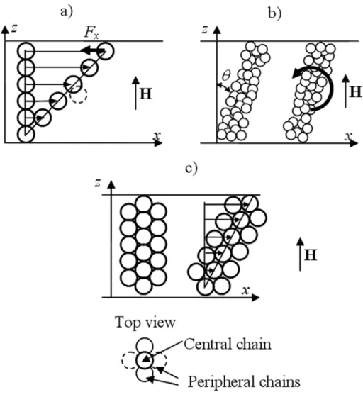
affine displacement of each particle along the direction of the shear, as depicted in Fig. 1a
[Bossis et al. (2002); Ginder et al. (1996); Klingenberg and Zukoski (1990)]. This model will
be hereinafter referred to as the affine model . As the particle chains are tilted by the
straining motion, the horizontal component of the magnetic attractive force, Fx, acting
between particles first increases, then reaches a maximum and finally decreases with the
strain. At the strain for which the force is maximum, the chains are considered to become
unstable and to break, inducing the flow of the MR suspension. The yield stress is simply
calculated as the maximal interparticle force Fx multiplied by the number ns of chains per unit
surface of the upper rheometer plate:
Y n Fs x
σ = ⋅ . (1)
A more general model, based on fundamental thermodynamic relations, considers the shear
stress in a sheared suspension as a result of the change in its internal energy:
/
U
σ = ∂ ∂ , γ (2)
where γ is the strain and U is the suspension internal energy per unit volume (see Fig. 1b) [Bossis et al. (1997); Bossis et al. (2002)]. This model will be called here the thermodynamic
model. The static yield stress is also calculated in this case as the shear stress corresponding
to the maximum in the stress versus strain curve. This model can be used whatever the
description of the structure and, here, one should distinguish the microscopic description from
the macroscopic one. The difference between both descriptions stands in the fact that, in the
former the loss of contact between two neighboring particles is taken into account for the
estimation of the energy dependency with the strain, contrary to the latter in which only the
change of the energy due to the inclination of the aggregates is considered. As a result, both
approaches give similar predictions if the interactions between particles are long ranged, as it
other hand, predictions are very different if strong short range forces exist, as it happens in the
case of particles with high magnetic permeability [Bossis et al. (1997)]. It is worth nothing
that the affine model is just a particular case of the microscopic approach of the
thermodynamic model, for which both force and energy-based calculations of the stress, Eqs.
(1) and (2) respectively, are completely equivalent. In the affine microscopic model, the
interparticle forces are directly calculated either analytically [Ginder et al. (1996)] or
numerically via multipolar approach [Clercx and Bossis (1993); Klingenberg and Zukoski
(1990)] or finite element method [Bossis et al. (2002); Ginder and Davis (1994)]. In the
macroscopic approach of the thermodynamic model a mean field theory must be used, usually
the Maxwell-Garnet one which does not require assumptions of any specific particle
arrangement at the microscopic scale (one should only define the macroscopic features of the
structure, i.e. columns, ellipsoids or stripes) and allows obtaining general results [Bossis et al.
(1997)]. As a consequence, the microscopic approach ensures a much better correspondence
with experiments for MR suspensions composed of particles with high magnetic permeability,
FIG. 1. Different model geometries used for stress calculations in MR fluids. The microscopic affine model [Ginder et al. (1996)] supposes affine displacement of particles with shear (a). Arrows denote displacement vectors of particles. The stress arises from the restoring interparticle force Fx. If a given particle leaves its
equilibrium position (dashed sphere in (a)), it will be immediately stacked on top of the closest particle, showing that the structure is mechanically unstable. The macroscopic thermodynamic model [Bossis et al. (1997)] assumes formation of thick columns and ignores arrangement of particles within them (b). The stress comes from
the restoring magnetic torque denoted by a bold arrow. A more realistic structure combines the features of both previous ones. Under strain, some particles experience affine motion, creating gaps between them, and the others
are drawn into these gaps, maintaining the mechanical contacts with neighboring particles. One of the simplest structures corresponding to this picture is the BCT cluster shown in (c), which is found to be the most favorable for the energetic point of view [Tao and Sun (1992), Clercx and Bossis (1993), Tao and Jiang (1998)]. The stress
response of such structure arises from both the longitudinal striction (due to the formation of gaps) and the restoring magnetic torque.
When these two models are applied to the system studied in the present work
(suspension of strongly magnetizable particles at 0.50 volume fraction), it is found that the
affine microscopic model gives the correct order of magnitude for the yield stress (360 Pa vs.
200 Pa experimental value- for the yield stress upon application of a field of 18.5 kA/m)
forces. On the other hand, the macroscopic approach of the thermodynamic model strongly
underestimates the yield stress (9 Pa vs. 200 Pa for a magnetic field of 18.5 kA/m). Thus, at a
first view, we may be tempted to restrict our analysis to the affine model. However, it is clear
that the rupture of chains by keeping an equal gap between neighboring particles as supposed
in this model and depicted in Fig. 1a is not realistic see also comments on the caption of
Figure 1. Furthermore, it is well known that in concentrated MR suspensions, thick columnar
aggregates or other more isotropic structures are built upon field application, but single chains
have never been observed [Cutillas and Bossis (1997)]. Therefore, from a realistic point of
view, the thermodynamic model, which is based on general thermodynamic principles and
assumes the formation of thick columns, is much more appropriate since it considers the
correct size and shape of the aggregates. As already mentioned, the main reason for which the
macroscopic model does not fit well to experimental results lies in the use of dipolar approach
for interparticle interactions. This approach strongly underestimates the magnetic forces
between particles and, as a consequence, gives too low values for the yield stress. In more
details, the shear stress predicted by this model is given by the following relation:
2 0 2 2 ( ) (1 ) H γ σ µ µ µ= E− ⊥ +γ , (3)
with µ0=4π·10-7 H/m being the magnetic permeability of vacuum, H the magnetic field intensity inside the MR suspension, and µE and µ⊥ the diagonal components of the magnetic permeability tensor of the suspension with respect to a frame of reference with main axes in
the directions parallel and perpendicular to the column aggregates. These last magnitudes will
be called hereinafter longitudinal and transverse permeabilities for brevity. The yield stress is
found as the maximum stress of the stress-strain dependency Eq. (3)-, which is reached at a
the suspension stress are taken into account through the values of these magnitudes. The
inaccuracy of the dipolar approach can be corrected by including higher-order magnetic
interactions in the suspension permeability. However as will be shown by our theory (see
section III-B), the main contribution to the yield stress of suspensions of highly magnetizable
particles does not come from the value of the permeability, but from the change of the energy
with the formation of gaps and, therefore, from the derivative of the permeability with respect
to the gap between the particles. Thus, Eq. (3) should include a term containing ∂µ γE/∂ and /
µ⊥ γ
∂ ∂ .
The most rigorous way to take into account the interparticle gap effect on the strength
of a real structure is to conduct numerical simulations of the structure dynamics under slow
shear flow. Bonnecaze and Brady (1992) simulated the structure of electrorheological fluids
by the molecular dynamic method using multipolar interactions between particles, and
calculated the electrostatic stress with the help of Eq. (2). However, they reported rather
strong irregular oscillations of the stress response, as a result of the structure breakage and
reformation, and the predicted values of the yield stress were too low.
In contrast to simulations, the microscopic models of Bossis et al. (1997), assuming
more realistic multi-chain or zigzag-like clusters, provide a simpler picture of the interparticle
gap effect on the suspension yield stress. The authors supposed that small interparticle gaps
were formed under shear and calculated the stress via the derivative of the internal energy
(Eq. (2)). The theoretical yield stress was found to strongly depend on the strain at which the
interparticle gaps were formed. If the particles begin to separate from each other at zero strain
(as it is the case of the affine deformation of multi-chain clusters), then the multipolar
interactions predict a yield stress σY =6.5µ H0 2 for the 50 vol.% MR suspension of the present work, which is an order of magnitude lower than the stress measured in our
experiments. If the particles form zigzag-like clusters, they begin to separate at a non-zero
critical strain that corresponds to the full extension of the clusters. This gives a several times
increase of the yield stress as compared to affine models. However, at the critical strain, the
stress experiences a jump of several orders of magnitude, inconsistent with experimental
observations. Therefore, neither affine nor zigzag-like cluster models can be applied, in the
form they are reported in literature, to highly concentrated MR suspensions.
In the next subsection we will develop a new model, which will be based on a realistic
microscopic structure and will give correct values for the yield stress of MR suspensions in
the concentrated regime. For this, we will take into account all the requirements for the
particle structure that are drawn from the analysis performed above for previous models: (i)
interparticle gaps must appear in the structure in order to obtain realistic values of the yield
stress; (ii) the structure must be able to sustain a relatively large extension, in such a way that
the critical strain would be high enough to give appropriate values of the yield stress; (iii) the
failure of the structure must occur without any considerable jump in the stress. This implies a
continuous formation of interparticle gaps during the shear strain of the clusters.
B. Theoretical model
Let us consider a simple shear deformation of a concentrated MR suspension confined
between two parallel plates. An external magnetic field of intensity H0 is applied
perpendicularly to the plates. If the field is strong enough, it will induce percolating structures
of magnetic particles. We will assume that these consist of body-centered tetragonal (BCT)
structures, with four peripheral chains shifted vertically by a particle radius with respect to a
central chain, and with neighboring particles being in contact at zero strain. This structure was
found to be the most favorable from the energetic point of view [Tao and Sun (1992), Tao and
electrorheological fluids electric counterparts of magnetorheological suspensions [Chen et
al. (1992)]. Applied to our case of a highly concentrated suspension, this structure meets all
the requirements mentioned at the end of the previous subsection, if we assume that the
central chain deforms in an affine manner with the applied strain and the peripheral chains
remain always in contact with the central one (see Fig. 1c). Since in our experiments we used
surfaces with high rugosity, the structure is supposed to be always stuck to both plates, wall
slip being absent, until its failure at the critical strain. Thus, when the upper plate is displaced
a certain distance ∆x, the structure is strained by a magnitude γ =∆x/h, where h is the gap between the plates. We suppose that the structure deforms homogeneously until its failure and
this assumption does not contradict to the condition of its mechanical stability: in the
increasing branch of the stress-vs.-strain curve, any small perturbation of the homogeneous
strain field should decay with the time. Under the strain, the particle structure turns along the
vorticity axis and extends along its major axis (Fig. 1c), both effects contributing to the shear
stress. On the one hand, the extension creates interparticle gaps and, consequently, restoring
forces along the main axis of the structure. On the other hand, the structure rotation induces a
restoring magnetic torque that tends to turn back the structure and align it with the magnetic
field.
In order to calculate the stress response for a given stationary strain, γ, we must first obtain the magnetic permeability tensor of the suspension. Under homogeneous deformation,
the main axes of magnetization of the suspension coincide with the axes of the BCT
structures. Thus, in a reference frame linked to the particle structures, the magnetic
permeability tensor is diagonal and has two dissimilar components: µE along the major axis of the structures and µ⊥ along their minor axis. From these, the magnetic permeability tensor with respect to the laboratory (rheometer) reference frame is obtained by rotation of the
reference frame along the y-axis. The two components, µzz and µxz, which have importance in our calculations, are expressed as follows:
2 2 2 1 1 1 zz γ µ =µE +γ +µ⊥ +γ , (4) 2 ( ) 1 xz γ µ = µ µE− ⊥ +γ , (5)
µE and µ⊥ can be calculated as a function of the interparticle gap δ by solving Maxwell s equations by finite element method simulation. These calculations are reported in details in
the Appendix, together with interpolation formulas for the dependencies of µE and µ⊥ with the relative gap, δ/a, with a being the particle radius. The relative gap δ/a is related to the strain by the following formula: δ/a=2
(
1+ − . Thus, the magnetic permeability γ2 1)
components can be expressed in terms of the strain γ.Below the yield point, and under static straining conditions, the MR suspension may
be considered as a magnetic, anisotropic elastic solid. For such continuum, the stress tensor is
expressed, in its most general form, by the equation given by Landau and Lifshitz (1984):
(
)
, 1 2 ik ik i k k i ik T F F H B H B σ = δ +⎛⎜ ∂γ ⎞⎟ + + ∂ ⎝ ⎠ H # # , (6)where H and B are respectively the magnetic field intensity and the magnetic flux density
inside the suspension, γik are the components of the strain tensor, δik those of the unit tensor, and F# is a thermodynamic function defined through the free energy of the suspension per
0 0 F ≡ − ⋅ = −F F
∫
⋅d H H B B H # , (7)with F0 being the free energy per unit volume of the suspension in the absence of magnetic
field. Note that Shkel and Klingenberg (1999) used similar expressions for electrorheological
fluids in the small deformation limit for calculations of the dielectric tensor and the storage
modulus. We shall exploit these formulas in a broader range of strains, which will allow us to
calculate the yield stress of the suspension.
Magnetic particles used as solid phase in MR suspensions, usually show non-linear
magnetization behavior, i.e. their magnetic permeability depends on the applied magnetic
field strength. Similarly, the magnetic permeability of MR suspensions also presents a
dependency with the applied magnetic field. However, in the relatively narrow range of
magnetic field intensities used in our experiments, we may consider, within a good
approximation, that the suspension permeability is field-independent. In this case, the
magnetic flux density of the suspension presents a linear dependency with the magnetic field
strength: Bi =µ µ0 ikHk. By substitution of this into Eq. (7), the expression for the thermodynamic function F# reduces to:
2 2 2 2 2 0 0 0 0 0 2 0 2 1 1 1 1 1 2 2 2 1 2 1 F F µ µ H µ µ H F µ µ H µ µ H γ γ γ ⊥ ⊥ ⊥ = − − = − − + + E E E # , (8)
where cosHE =H θ and H⊥ =Hsinθ are the components of the internal magnetic field in the directions parallel and transverse to the BCT structures, respectively; θ is the strain angle (see Fig. 1b), which is related to the strain through the formula γ =tanθ . In the experimental case studied in this work, the internal magnetic field, H, in the thin layer of suspension
confined between the two plates of the rheometer is related to the external applied field, H0,
2 0 0 2 (1 ) zz H H H γ µ µ µ γ⊥ = = + + E . (9)
By substitution of Eqs. (5) and (8) into Eq. (6), we obtain the final expression for the shear
stress (xz-component of the stress tensor) as a function of the applied strain and the magnetic
field strength:
(
)
2(
)
2 2 2 0 2 2 0 2 2 0 2 1 1 1 (1 ) 2 1 1 2 1 H γ H µ µ γ H γ σ µ µ µ γ µ γ γ γ⊥ γ µ µ µ γ ⊥ ⎡∂ ∂ ⎤ ⊥ = − − ⎢ ⋅ + ⋅ ⎥+ − + ⎣∂ E + ∂ + ⎦ + E E , (10)with the expression for ∂µ γE/∂ given in the Appendix. The first term in Eq. (10) is the elastic contribution due to the restoring magnetic torque acting on the tilted BCT structures. This
term is also connected to the variation of the suspension magnetic permeability with the
rotation of the structures. The second term stands for the elastic contribution due to the
restoring striction forces that tend to compress the structures extended by the shear. In other
words, these forces tend to reduce the interparticle gaps induced by the strain. From the
macroscopic point of view, this term is related to the variation of the magnetic permeability
with the extension of the aggregates. The last term is the Maxwell stress, which arises from
the deformation of the structures under the applied magnetic field. On the other hand, the first
and the second terms come from the effect of deformation on the magnetic properties of the
structures. Analysis shows that the first and the last terms of Eq. (10) are negligible as
compared to the second one. This confirms the extreme importance of the interparticle gaps as
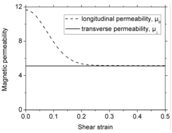
FIG. 2. Longitudinal, µE, and transverse, µ⊥, components of the magnetic permeability tensor of a suspension consisting of Fe-CC particles dispersed in mineral oil (volume concentration 50 %) as function of the applied
shear strain.
IV. RESULTS
The strain dependency of both µE and µ⊥ is shown in Fig. 2 for the suspension under study in the present work. In the range of the strains, 0 < γ < 0.5, the longitudinal permeability, µE, shows an important decrease with the strain. This decrease is connected with the appearance and enlargement of gaps between the particles of a same chain when the
BCT structures are extended by the shear (see Fig. 1c). The size of these gaps increases
proportionally to γ2, and this provokes a quite strong variation of µE. On the other hand, the transverse permeability, µ⊥, appears to be independent of the strain. This can be easily understood since µ⊥ depends mainly on the distance between particles of two opposite peripheral chains (dashed circles in the top view of Fig. 1c). The initial separation between
these particles is equal to ( 3 1) (2 )− ⋅ a 01.5a. When the BCT structure is extended, there is an approach of these particles, but at small enough strains it is almost negligible with respect
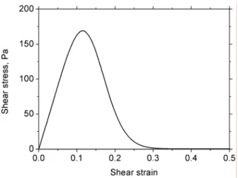
FIG. 3. Theoretical stress-strain curve for a suspension consisting of Fe-CC particles dispersed in mineral oil (volume concentration 50 %). The applied magnetic field is H0=18.5 kA/m.
Fig. 3 shows the stress-strain dependency calculated with the help of Eq. (10) for the
MR suspension under study (50 vol.% of Fe-CC in mineral oil) upon application of a field
H0=18.5 kA/m. As expected, when the strain increases, the stress first increases, then reaches
a maximum, and finally decreases gradually towards nearly zero values at γ >0.3. Note that the maximum of the stress takes place at a critical strain, γcr≈0.115, much lower than that predicted by the macroscopic model of Bossis et al. (1997): γcr =1/ 3≈0.58. This is not surprising because, in our model, the longitudinal component of the suspension permeability
falls with the strain quite rapidly (see Fig. 2), provoking a rapid increase of the stress at low
strains. On the other hand, in the macroscopic model of Bossis et al. (1997), the permeability
µzz decreases slowly with the strain, the structure rotation with respect to the applied field
being the only cause for the decrease in this model. Nevertheless, the critical strain γcr≈0.115 predicted for the BCT structure by the present model is two-three times larger than the one
calculated for single chains see Fig. 7 in the work by Bossis et al. (2002). Consequently, the
critical strain obtained in the present work should be large enough to ensure reasonable
predictions of the yield stress. As stated above, structures become unstable at strains γ >γcr and are thus supposed to break at the summit of the stress-strain curve. So, the yield stress
corresponds to the maximum of the stress-strain curve and is calculated by replacing the strain
γ by the critical strain γcr≈0.115 in Eq. (10): σ σ γY = ( cr).
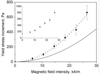
FIG. 4. Experimental and theoretical dependencies of the yield stress increment, ∆σ(H0)=σ(H0)−σ(0), on the magnetic field intensity, H0, for a suspension containing 50 vol.% of Fe-CC in mineral oil. The inset shows
the field dependency of the yield stress, σ(H0), without subtraction of the value at zero field, σ(0). Full squares stand for the experimental data and the solid curve for the theoretical prediction Eq. (10), replacing γ by γcr≈0.115. The dashed line represents the best fit of the experimental data to a power law ( ( 0)
n
H H
σ
∆ = )
the exponent of this best fit is 1.91 ± 0.07.
The values of the static yield stress (both experimental and theoretical) for the MR
suspension under study (50 vol.% of Fe-CC in mineral oil) are plotted as a function of the
applied field strength in Fig. 4. Since, as observed in the inset of this figure, the MR
suspension presents a non-zero experimental value of the yield stress at zero field, the net
effect of the magnetic field is better expressed by the difference of the yield stress at a given
magnetic field and that in the absence of field: ∆σ(H0)=σ(H0)−σ(0). We refer to this quantity as yield stress increment. The yield stress at zero field is likely due to the remnant
magnetization of the iron particles, as well as to non-magnetic colloidal interactions between
them, mainly van der Waals forces, which may induce the formation of particle aggregates in
the absence of applied field. The importance of these forces in suspensions of magnetic
As seen in Fig. 4, the yield stress increment increases gradually with the magnetic
field intensity. The experimental dependence of the yield stress increment is approximately
quadratic, as proved by the fact that the best fit to a power law gives an exponent of 1.91 ±
0.07 (dashed line in Fig. 4). The increment of the yield stress with the applied field is
commonly explained by the fact that, at higher fields, stronger magnetic forces act between
particles and, thus, stronger forces are required to separate them and to break the structures.
Concerning the predictions of our theoretical model, as observed in Fig. 4, the theory (without
adjustable parameters) still underestimates the experimental data by about 50%. One of the
reasons for such a discrepancy could be a polydispersity of the MR suspension. As stated by
Kittipoomwong et al. (2005), small magnetic particles may form locally more compact
aggregates and cause the larger particles to form more robust aggregates. Such aggregates
resist better to the applied strain and give a higher yield stress compared to that of the
monodisperse MR fluid at the same volume fraction of particles.
V. CONCLUSIONS
We have presented in this work reliable experimental data of the magnetic
field-induced static yield stress of a MR suspension with concentration near the limit of
maximum-packing fraction. Both the preparation of the MR suspension and the experimental protocol
followed for the measurement of the static yield stress were carefully chosen to guarantee
reproducibility of the results. In addition, we have developed a model for the static yield stress
of highly concentrated MR suspensions upon magnetic fields. This model is based on the key
hypothesis that interparticle gaps inside the field-induced particle structures must appear when
they are subjected to shear strain, at the same time that their mechanical stability must be
maintained. This perspective supposes an original contribution with respect to standard
easily fulfilled by considering a structural unit consisting of five chains of particles located at
positions of a BCT structure. When this structure is sheared the particles of the central chain
are supposed to move in an affine way, whereas the particles of the peripheral chains remain
in contact with those of the central chain ensuring the mechanical stability of the structure.
Estimations of our model show that the main contribution to the stress of highly concentrated
MR suspensions comes from the change in the magnetic permeability of these, as interparticle
gaps are forced and enlarged by the shear stress. Therefore, the neglect of this particular
aspect in most of the existing macroscopic models is the likely reason for their failure when
applied to highly concentrated suspensions of strongly magnetizable particles. This last
statement is supported by the quite good agreement obtained between predictions of our
model and experimental results, taking into account that our model does not include any
adjustable parameter. The theoretical model developed in this work will be, in the near future,
extended to the steady state shear flow of MR suspensions taking into account eventual flow
instabilities in highly concentrated regime. Finally, the simple interpolation formulas issued
from the present model could be useful for engineering calculations.
ACKNOWLEDGEMENTS
We would like to thank Professor Andrey Zubarev for helpful discussions. Financial
support by projects Fis2009-07321 (Ministerio de Ciencia e Innovación, Spain),
P08-FQM-3993 and P09-FQM-4787 (Junta de Andalucía, Spain), Biomag (PACA, France) and
Factories of the Future (Grant No. 260073, DynExpert FP7) is gratefully acknowledged.
MTL-L also acknowledges financial support by Universidad de Granada (Spain). LR-A
APPENDIX: PERMEABILITY CALCULATIONS
We calculated the longitudinal and transverse magnetic permeabilities of the MR
suspension by solving Maxwell s equations by means of finite element method (FEM)
simulations. These simulations were performed with the help of the free software FEMM
[Meeker (2009)]. For this aim, and although the BCT structures of our model are
three-dimensional (3D), we considered a planar problem since 3D-problems cannot be implemented
with FEMM software. Nevertheless, we expect that the simplification of the real 3D-problem
to a planar-one will not be a restriction for the validity of the results obtained in this appendix.
The representative planar cells used for the calculations of both components of the
magnetic permeability tensor, µE and µ⊥, are shown in Figs. A1 and A2, respectively. The vertical axis of symmetry of the first cell coincides with the major axis of the BCT aggregate.
The two closely spaced semi-circles represent particles belonging to the central chain and the
two lateral circles represent particles of the peripheral chains. The whole BCT structure is
relatively long (aspect ratio /(2h a 3)≈ ) and can be considered as an infinite stack of the 40 unit cells. The horizontal dimension d of the first cell (Fig. A1) is chosen to be equal to the
mean distance between BCT structures in their hexagonal arrangement:
2 5 /(3 3 ) 2.46 (2 )
d = π Φ ⋅ ≈a ⋅ a , where a is the particle radius and Φ=0.5 the volume
fraction of particles in the suspension. In this figure, the applied magnetic field is oriented
vertically and the intensity H of the internal magnetic field (averaged over the cell volume) is
imposed on both lateral borders of the cell. Periodic boundary conditions are used for the
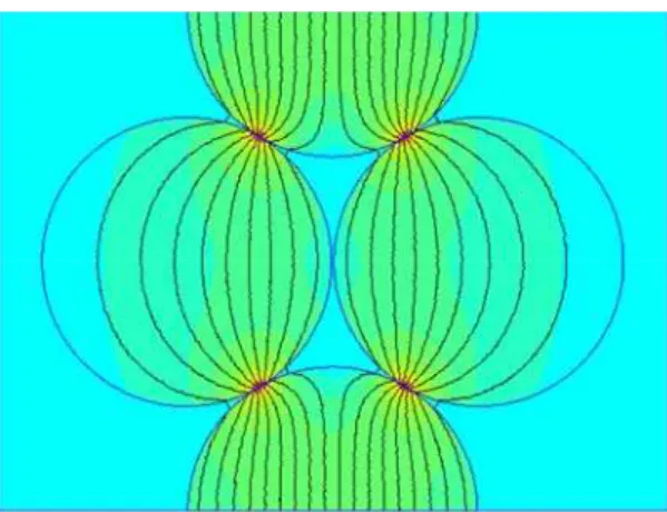
FIG. A1. Elementary cell of the MR suspension used for the calculation of the longitudinal magnetic permeability, µE. The surface plot of the magnetic flux density and the magnetic field lines are shown. The red
spots correspond to the regions of high magnetic flux density in the vicinity of the contact points between spheres.
For the calculation of the transverse magnetic permeability, µ⊥, the external magnetic field must be applied perpendicularly to the BCT structure. However, for the convenience of
definition of the boundary conditions, we can still reduce our problem to longitudinal
magnetic fields. For this aim, a 90º rotation of the internal structure shown in Fig. A1 is
enough. By doing it we obtain the unit cell used for the calculations of µ⊥ (Fig. A2). In this figure, the two closely spaced circles represent particles of the central chain and the two
semi-circles stand for particles of peripheral chains. In this cell, the external magnetic field is
vertical and the boundary conditions are similar to those used for the cell of Fig. A1.
FIG. A2. Elementary cell of the MR suspension used for the calculation of the transverse magnetic permeability, µ⊥. The surface plot of the magnetic flux density and the magnetic field lines are shown.
The non-linear magnetic properties of carbonyl iron particles are well described by the
Fröhlich-Kennelly law [Jiles (1991)]:
1 ( 1) ( 1) i S p S i p M M H µ µ = + −µ + − , (A.1)
where µp is the magnetic permeability of the particles, µi = 250 and MS = 1.36·106 A/m are,
respectively, the initial permeability and the saturation magnetization of the particles, and Hp
is the magnetic field intensity inside the particles.
Once the magnetic field distribution is found for both cells (Figs. A1 and A2), the
corresponding permeability component is calculated by the following formula:
, , 0 1 B dV H V µE⊥ =µ ⋅
∫
E⊥ , (A.2)where H is the intensity of the mean magnetic field inside the MR suspension, imposed on the
lateral borders of the cell and related to the external field, H0, via Eq. (9). The integration in
Eq. (A.2) is performed over the whole cell volume V. Recall that the simulations are
performed considering planar geometries, and this means that the circles of Figs. A1 and A2
are taken, from the point of view of the FEM simulation, as infinite cylinders oriented
perpendicular to the plane of the page. In order to evaluate the numerical error related to this,
we calculated by FEM simulation the longitudinal magnetic permeability of an infinite chain
composed of touching spheres, and that of an infinite chain composed of touching cylinders
with their axes perpendicular to the applied magnetic field. Simulations showed that the
magnetic permeability of the chain of spheres is 3.43 times smaller than that of the chain of
cylinders. Consequently, all the results obtained for the multi-chain geometry of Figs. A1 and
A2, including those of Eq. (A.2), were reduced by the factor 3.43. This is perhaps a rough
correspondence between theoretical and experimental values of the yield stress, as observed in
Fig. 4.
For the calculation of the components of the magnetic permeability tensor of the
structure subjected to uniaxial extension under the shear forces, we moved apart the initially
touching circles (which represent particles of the central chain) and approached the
non-touching ones (which represent particles of opposite peripheral chains), in such a way that
there was no fracture of the structures represented in Figs. A1 and A2. By changing the
distance between the initially touching circles by steps of 10−4⋅ , we obtained the values of a
µE and µ⊥ as functions of the relative interparticle gap, δ/a. The best nonlinear fits of these functions (taking into account the correction factor 3.43, mentioned above) are given by the
following formulas: 1 3 4 2 ( / ) exp δ a ( / )a µ α= ⎛⎜− α ⎞⎟+ + ⋅α α δ ⎝ ⎠ E , (A.3) 5.118 const µ⊥ ≈ = , (A.4)
with αi (i=1-4) being numerical constants of values α1=6.4925, α2=0.01164, α3=5.1636 and
α4=-0.00435. Replacing the relative gap in Eq. (A.3) by the formula δ/a=2
(
1+ − , we γ2 1)
obtain the longitudinal magnetic permeability, as a function of the strain γ. Finally, the derivative of µE with respect to the strain, which appears in Eq. (10) for the stress, is given by the following expression:(
2)
1 4 2 2 2 2 1 1 ( / ) 2 exp ( / ) 1 a a γ µ µ δ α α γ γ δ γ α α γ ⎡ ⎛ + − ⎞ ⎤ ∂ = ∂ ⋅∂ = −⎢ ⎜− ⎟+ ⎥ ⎢ ⎜ ⎟ ⎥ ∂ ∂ ∂ ⎢ ⎜ ⎟ ⎥ + ⎝ ⎠ ⎣ ⎦ E E . (A.5)References
Barnes, H. A., J. F. Hutton, and K. Walters F. R. S., An introduction to rheology (Elsevier,
Amsterdam, 1993).
Bonnecaze R. T., and J. F. Brady, Yield stresses in electrorheological fluids, J. Rheol. 36,
73-115 (1992).
Bossis, G., E. Lemaire, O. Volkova, and H. Clercx, Yield stress in magnetorheological and
electrorheological fluids: A comparison between microscopic and macroscopic structural
models, J. Rheol. 41, 687-704 (1997).
Bossis G., O. Volkova, S. Lacis, and A. Meunier, Magnetorheology: Fluids, Structures and
Rheology, Lect. Not. Phys. 594, 186 230 (2002).
Clausen, J. R., D. A. Reasor Jr, and C. K. Aidun, The rheology and microstructure of
concentrated non-colloidal suspensions of deformable capsules, J. Fluid Mech. 685,
202-234 (2011).
Clercx, H. J. H., and G. Bossis, Many-body electrostatic interactions in electrorheological
fluids , Phys. Rev. E 48, 2721 2738 (1993).
Chen, T-J., R. N. Zitter, and R. Tao, Laser diffraction determination of the crystalline
structure of an electrorheological fluid, Phys. Rev. Lett. 68, 2555 2558 (1992)
Chin, B. D., J. H. Park, M. H. Kwo, O. O. Park, Rheological properties and dispersion
stability of magnetorheological (MR) suspensions, Rheol. Acta 40, 211-219 (2001).
Cutillas, S., and G. Bossis, A comparison between flow induced structures in
De Vicente, J., F. González-Caballero, G. Bossis, and O. Volkova, Normal force study in
concentrated carbonyl iron magnetorheological suspensions, J. Rheol. 46, 1295-1303
(2002).
Ginder, J. M., and L. C. Davis, Shear stresses in magnetorheological fluids: Role of magnetic
saturation, Appl. Phys. Lett. 65, 3410 3412 (1994).
Ginder J. M., L. C. Davis, and L. D. Elie, Rheology of magnetorheological fluids: Models
and measurements, Int. J. Mod. Phys. B 10, 3293-3303 (1996).
Jiles, D., Introduction to Magnetism and Magnetic Materials (Chapman and Hill, London,
1991).
Kittipoomwong D., D.J. Klingenberg, and J.C. Ulicny, Dynamic yield stress enhancement in
bidisperse magnetorheological fluids, J. Rheol. 49, 1521-1538 (2005)]
Klingenberg D. J., and C. F. Zukoski, Studies on the steady-shear behavior of
electrorheological suspensions, Langmuir 6, 15-24 (1990).
Landau, L. D., and E. M. Lifshitz, Electrodynamics of Continuous Media (Pergamon, New
York, 1984).
Laun, H. M., C. Gabriel, and G. Schmidt, Primary and secondary normal stress differences
of a magnetorheological fluid (MRF) up to magnetic flux densities of 1 T, J.
Non-Newtonian Fluid Mech. 148, 47-56 (2008a).
Laun, H. M., G. Schmidt, C. Gabriel, and C. Kieburg, Reliable plate plate MRF
magnetorheometry based on validated radial magnetic flux density profile simulations,
Larson, R. G., The Structure and Rheology of Complex Fluids (Oxford University Press, New
York, 1999).
Meeker, D.C. Finite Element Method Magnetics, Version 4.2 (15Jul2009 Mathematica
Build), http://www.femm.info.
Onoda, G. Y., and E. R. Liniger, Random loose packings of uniform spheres and the
dilatancy onset, Phys. Rev. Lett. 64, 2727-2730 (1990).
Phulé, P. P., M. T. Mihalcin, and S. Gene, The role of the dispersed-phase remnant
magnetization on the redispersibility of magnetorheological fluids, J. Mater. Res. 14,
3037 3041 (1999).
Russell W. B., D. A. Saville, and W. R. Schowalter, Colloidal dispersions (Cambridge
University Press, Cambridge, 1989).
Shkel, Y. M., and D. J. Klingenberg, A continuum approach to electrorheology, J. Rheol.
43, 1307-1322 (1999).
Tao R. and Qi Jiang, Structural transformations of an electrorheological and
magnetorheological fluid , Phys. Rev. E 57, 5761-5765 (1998)
Tao R. and J.M. Sun, Three-dimensional structure of induced electrorheological solid ,
Phys.Rev. Lett. 67, 398 401 (1991)
Zhou, J. Z. Q., T. Fang, G. Luo, and P. H. T. Uhlherr, Yield stress and maximum packing