HAL Id: hal-01302023
https://hal.archives-ouvertes.fr/hal-01302023
Submitted on 13 Apr 2016
HAL is a multi-disciplinary open access
archive for the deposit and dissemination of
sci-entific research documents, whether they are
pub-lished or not. The documents may come from
teaching and research institutions in France or
abroad, or from public or private research centers.
L’archive ouverte pluridisciplinaire HAL, est
destinée au dépôt et à la diffusion de documents
scientifiques de niveau recherche, publiés ou non,
émanant des établissements d’enseignement et de
recherche français ou étrangers, des laboratoires
publics ou privés.
Annotated Component-Based Description for
Application Composition
Christian Brel, Philippe Renevier-Gonin, Anne-Marie Pinna-Déry, Michel
Riveill
To cite this version:
Christian Brel, Philippe Renevier-Gonin, Anne-Marie Pinna-Déry, Michel Riveill.
Annotated
Component-Based Description for Application Composition. ICSEA 2012, The Seventh
Interna-tional Conference on Software Engineering Advances, Nov 2012, Lisbonne, Portugal. pp.506-511.
�hal-01302023�
Annotated Component-Based Description for Application Composition
Christian Brel, Philippe Renevier-Gonin, Anne-Marie Pinna-Déry, Michel Riveill
Laboratoire I3S - UMR7271 - UNS CNRS2000, route des Lucioles - Les Algorithmes BP 121 - 06903 Sophia Antipolis Cedex – France
{christian.brel, philippe.renevier, anne-marie.pinna, michel.riveill}@unice.fr
Abstract – One possible way of developing applications faster is
by composing existing applications. In order to support developers this way, we propose a composition approach manipulating both Functionalities and User Interfaces. We present a model of annotation for describing Component-Based applications. By tagging the components with their “ui” and functional concerns, we take into account the UI part of application at a same level as business part. Thanks to such annotations, we define a substitution between components in order to merge controls, inputs or outputs.
Keywords–application composition; ontology; component-based architecture
I. INTRODUCTION
Nowadays, the trend in software usage is to consume specialized applications. End-users can use the same functionality in several situations, i.e., with several applications. For example, Google Maps is often integrated for geo-localization. In an idealistic way, developers must be able to reuse functionalities without (or with minor) developments. To support developers in their task of combining features from several component-based applications, we contribute towards reducing developers’ efforts. We propose an application composition through its User Interface (UI). Our composition preserves the functional linking between components of the applications. Considering a UI as an assembly of components, we explore the composition via their ports. Using the fact that a port can be provided by a component or required by it, we add some annotations about the role the port plays for its attached unit. The added information lets the different components to be combined to obtain a running application.
Section II presents a description of related work. Section III describes the model that an application has to respect in order to be composed. A case study to illustrate our proposed model is shown in Section IV. After the presentation of the composition by substitution in Section V, Section VI details the substitution between two elements. The paper finished with a discussion about our work in Section VII and a conclusion in Section VIII.
II. RELATED WORK
The described problem is naturally related to the state-of-the-art in software composition and UI composition. For software composition, “Composition can be defined as any possible and meaningful interaction between the software
constructs involved” according to [5] where a taxonomy of composition mechanisms (e.g., orchestration, aspect oriented programming, etc.) is defined. When the application code is available, solutions, such as aspect oriented programming, are meaningful. On the contrary, when the application code is not available, we can only access to published interfaces and we have to use connectors [7] to perform the composition.
For UI composition, we identify two different approaches. In the first approach, the UI composition is based on abstract description, like in UsiXML [6], in the ServFace project [8], Alias [10] and in Transparent Interface [4]. Those models are defined by XML languages. Final UI are obtained thanks to transformations of those models. In the second approach, the UI composition is based on “UI Components”. These ones are reusable high-level widgets, available in repositories. “UI components” are reused by applying design pattern (code level) and detecting pattern of use (UI level). Compose [3], COTS-UI [1], CRUISe [9], WinCuts [12], UI façades [11] and on-the-fly mashup composition [13] illustrate such kind of UI composition.
From the analysis of these works, we note that we can compose the UI (respectively, the functional parts) of former applications, but the other side (respectively, the UI) has to be built again. Moreover, none of these works allows the reusing of former applications with supporting replacement of UI parts. Our goal is to compose applications and in particular their UI, not only by juxtapositions, but also by substitutions between former components of the UI. To obtain a functional application, we also want to preserve former functional links between components of application, in particular between the UI and the business part.
Our proposition is based on applications made of black-box components. We propose a composition model based on roles and ports of those components. The roles are expressed as annotations. The UI are also represented as component assemblies. The composition will be performed by transforming the manipulation on an abstract representation to manipulation on components.
III. APPLICATION MODEL BASED ON PORTS AND ROLES
In order to be compliant with our composition method, the existing applications must follow a clear separation between the functionalities (business part) and the UI (separation of concerns). A Component may belong to the two parts. Each Component is described with its ports that we can tag with one of the application concerns, e.g., a port used for a UI
concern will be tagged as “UI”. Each Component may have required ports (ports required to obtain desirable behavior of another Component) and may have provided ports (ports that Component can provide to other Components). Moreover, each port of a Component must be annotated with a “role” representing the involved behavior of the Component. This role can be Trigger, Input or Output. Trigger describes the fact that through its attached port, the Component can call another Component. It can be the button to trigger a particular action or it can be an observable “Component” notifying its observers. Input is used to describe a port to get some data. The Component with an Input port can provide data to other Components (like an “input text” in UI or any “Getter” facet of a Component). Output is used to describe a port to set some data. The Component can receive data to store or to display (like a “list” or a “label” in UI or any “Setter” facet of a Component). An application to compose must be provided with the annotations of ports of its Components. Those annotations are about roles (trigger, input, output / provided or required) or kind (“UI” or not, i.e., Business). In the remainder of the paper, we use the following acronyms: rt - “required-trigger”, pt - ”provided-trigger”, ri - “required-input”, pi - ”provided-input”, ro - “required-output” and po - ”provided-output”.
IV. ILLUSTRATION WITH A CASE STUDY
We consider two applications:
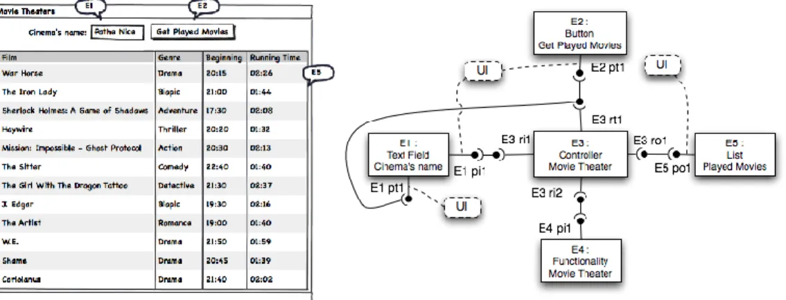
1. “Movie Theaters”, shown in Figure 1, an application displaying movies played in a cinema. There are a text field to entering the name of the cinema (E1), a “get played movies” button (E2) and a display area to list the played movies (E5). The list can also be obtained by validation with “Enter” key in text field (E1).
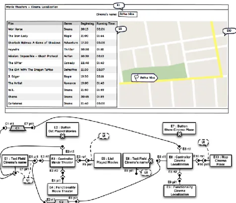
2. “Cinema Localization”, shown in Figure 2, an application displaying the location of a cinema on a map (e.g. using Google Maps). Its UI is also simple: a text field to entering the name of the cinema (E6), a “show cinema place” button (E7) and a map to show the localization of the cinema (E10).
These two applications could be composed in a different way, in order to obtain new applications. A possibility is to have at the same time both the list of the displayed movies and the localization of the cinema. A result of the composition’s UI is shown in Figure 3.
V. COMPOSITION BY SUBSTITUTION
An application appi is a set of Components {En}. We define “Ports”, the set of ports of a component, and “UsedPorts”, the set of used ports:
Ej appi, Ports(Ej) ={ Pn } is the set of the n ports of Ej UsedPorts(Ej, appi) = { Pk } is the set of used ports of Ej in appi
First, we define the role of the ports and their connectivity as the Linkable property, independently of the application in which components are used:
Ej appi1, Pm Ports(Ej), Role(Pm) {pi, po, pt, ri, ro, rt}
isProvided(Pm)⟺ Role(Pm){pi,po,pt}
isRequired(Pm)⟺ Role(Pm){ri,ro,rt} Ek appi2,Pm Ports(Ej), Pn Ports(Ek)
We denote rm = Role(Pm) and rn = Role(Pn)
Linkable(Pm, Pn)⟺(rm = ro and rn = po) or (rn = ro and
rm = po) or (rm = ri and rn = pi) or (rn = ri and rm = pi) or
(rm = rt and rn = pt) or (rn = rt and rm = pt)
We define a link between two components through two connected ports in an application as a property Link:
Link((Ej,Pm), (Ek,Pn), appi) is true if Ej and Ek are linked in a
appi through the ports Pm and Pn.
Such link is possible only if Ej belongs to appi , Ek belongs to appi, Pm belongs to UsedPorts(Ej, appi), Pn belongs to UsedPorts(Ek, appi) and Linkable(Pm, Pn). For each Component Ej, we define the set Links(Ej,Pm, appi):
Links(Ej,Pm, appi) = { (Ek, Pn), Ek appi,
Pn UsedPorts(Ek, appi) / Link((Ej,Pm),(Ek,Pn),appi) } For all ports, we define a property “isUIPort” indicating if the port has a “UI” concern and a function “isUIPortInApp” for contextual “UI” concern:
Ej,Pm Ports(Ej):
isUIPort(Pm)⟺isProvided(Pm) and Pm is tagged “UI” isUIPortInApp(Pm, appi) ⟺ (Pm UsedPorts(Ej, appi)
and isUIPort(Pm)) or (isRequired(Pm) and (Ek,Pn) /
isUIPort(Pn) and Link((Ej,Pm),(Ek,Pn), appi) ) Our composition is made through the construction of a new application, appr, initially defined as the union of all
former applications:
appr = 1nb appi where nb is the number of
applications being composed. Ej appi: Ej appr
UsedPorts(Ej, appr)= UsedPorts(Ej, appi) Ek appi, PmPorts(Ej), Pn Ports(Ek), Link((Ej,
Pm), (Ek,Pn), appr) = Link((Ej,Pm),(Ek,Pn), appi) Pm Ports(Ej), isUIPortInApp(Pm, appr) =
isUIPortInApp(Pm, appi)
The new application appr will change with the successive
substitutions. A substitution is made between a selection of pairs {(Ej, Pm)i} and a conserved pair (Ek,Pk). We define a “subst” function to operate substitution. In a few words, the substitution creates several connectors [7] in order to replace previous links involving substituted pairs by the kept one.
We denote PreLinksk the value of Links(Ek,Pk,appr) before the
substitution. We denote card(PreLinksk) the number of Components
in PreLinksk , i.e., the number of Components linked with Ek
through Pk.
For each pair (Ej, Pm)i, we denote PreLinksi the value of
Links(Ej, Pm, appr) before the substitution. We denote
number of Components linked with Ej through Pm. We denote sel
the set of the substituted pairs:
sel = {(Ej, Pm)i, i∈{1…z}}. (Ej, Pm)i ∈ sel, Pm UsedPorts(Ej, appr) ;
isProvided(Pm)= isProvided(Pk) We denote nk(i) :
nk(i) = 0 if the substitution doesn’t impact previous link with (Ek,Pk) , i.e., the new link and previous links are independent.
nk(i) = card(PreLinksk) if the substitution impacts previous link with (Ek,Pk), i.e., the new link and previous links are dependent (merged).
Figure 1. Movie Theater, UI and Components of application.
Figure 2. Cinema Localization, UI and Components of application.
If (nk(i) > 0 (Ej, Pm)i) then PreLinksk Links(Ek, Pk, appr) = , i.e., all connectors also replace the previous links involving the conserved pair (Ek,Pk) like in Figure 4. For each Component in sel, UsedPorts, Link and isUIPortInApp are impacted by substitution.
subst : 𝒫(PAIRS) × PAIRS → 𝒫(PAIRS)
subst(sel,(Ek,Pk))= { ( Ecj,a, Pmj,a)i x (Ecj,a,Pnj,a)i x (Ecj,a,Pky)i,
i∈{1...z}, y∈{1...nk(i)}, a∈{1...card(PreLinksi)} } (Ej, Pm)i∈ sel, Pm UsedPorts(Ej, appr)
(Ej, Pm)i∈ sel, Links(Ej,Pm, appr) = (Ej, Pm)i∈ sel,a∈{1...card(PreLinksi)}, Ecj,a is a new
Component of appr / {Pmj,a,Pnj,a } Ports(Ecj,a) and
{Pmj,a,Pnj,a} UsedPorts(Ecj,a,appr) and Linkable(Pm,Pmj,a) and
Linkable(Pnj,a, Pk)
Ecj,a, (Ecj,a , Pnj,a)∈ Links(Ek,Pk, appr)
(Ej, Pm)i, (Ecj,a,Pmj,a ) / Links(Ecj,a ,Pmj,a , appr) = PreLinksi (Ecj,a,Pmj,a ), (Ej, Pm)i / Links(Ecj,a ,Pmj,a , appr) = PreLinksi (Ej, Pm)i, nk(i)>0 => y ∈{1..Card(PreLinksk)}, Ecj,a is a new
Component of appr / {Pky} Ports(Ecj,a) and
{Pky} UsedPorts(Ecj,a,appr) and (E,P)∈ PreLinksk /
(Ecj,a, Pky) ∈ Links(E,P,appr)
As a result, Components no longer involved in links left are removed. The substitution of any pair (Ej,Pm) by a pair (Ek,Pk) is based on the annotations. The role of a port is used to define possible substitutions and the way connectors are used. This is explained in the Section VI. The use of the kind of ports (“UI” or not) is used as following. If before the substitution isUIPortInApp(Pm,appr) is different from isUIPortInApp(Pk,appr), then the substitution changes the
concern implied in the link, i.e., an input field may be replaced by a data coming from a “Business” Component. That is possible but in such case we could emit a notification.
VI. SUBSTITUTING TWO PAIRS
We now consider substitution between two pairs: a replaced pair and a conserved pair. The function “subst” can replace n pairs, but it is just n substitutions performed in parallel. We present the compatibility between the two pairs according to the role of the conserved pair.
In order to perform a substitution between two pairs (Component, Port with a role), we need to add a connector between the substituted pair and the conserved one [7]. Connectors may have several uses: (i) adapting formats of the data or (ii) defining a policy of substitution or (iii) adding a role when the new role makes the Component the “caller”. Thanks to the identification of the Connector and its roles, we can know define the “subst” function for two pairs. Indeed, in Sections VI.A, VI.B, VI.C and VI.D, we describe both the definition domain for two pairs and the results.
Figure 3. A Result for composition of “Movie Theater” with “Cinema Localization”.
A. Keeping a Provided Output
When keeping an output, there is no constraining on the role of substituted ports. By placing a connector before the Component having port playing the Output role, the substitution can be performed. This is a case in the “subst” function where nk(i) > 0 (Ej, Pm)i.
First, the connector may be used to adapt the format of data to display if the substituted role is also Output (a Conversion Connector in [7]) or to define a policy of displaying data if the substituted role is also Output (a mix between a Conversion Connector and a Data Access Connector in [7]). Such policy may be displaying all data, the last received data, etc. Secondly, the connector may also be used to store displayed data and can restitute them when asked if the substituted role is an Input (see Figure 4) (a Data Access Connector in [7]). Thirdly, the connector may also be used to generate an event when the output is updated if the substituted role is a Trigger (an Event Connector in [7]).
In Figure 4, the connector C1 can store displayed data from (E3,ro1) and can restitute them to (E8,ri1) when asked. With that solution, E5 doesn’t need to have a port playing a role of Input, but the Connector has both provided port with Output role for (E3,ro1), required port with Output role for (E5,po1) and required port with Input role for (E8,ri1). B. Keeping a Provided Trigger
As “Trigger” is the only one port’s role that makes the associated Component a “caller”, the role of the port in substituted pair must be also a “Trigger”. We place a connector after the kept “Trigger” for two reasons: (i) adapting the format of the “event” and (ii) defining the policy of the substitution (a mix between an Event Connector and a Procedure Call Connector in [7]). The connector can proceed a sequence between the two triggered actions or put them in parallel etc. This is a case in the “subst” function where nk(i) > 0 (Ej, Pm)i.
C. Keeping a Provided Input
An “Input” cannot replace an “Output” because of the direction of the data. Conversely, an “Input” may replace a “Trigger” (see Figure 5). The connector placed before the kept port can provide on demand (a Data Access Connector in [7]). At the same time, when called, the connector can generate an event and so it can “call” the requiring port (an Event Connector in [7]). The “Trigger” is “on access” (i.e., when the value is got). Of course, an “Input” can replace another “Input”. In that case, the connector is used to adapt the provided data to what is expected (a Conversion Connector in [7]). Keeping an “Input” is a case where nk(i) could either be 0 (pi replacing pi) or be greater than 0 (pi replacing a pt).
Figure 4 : (E5, po1) replacing (E6, pi1), connector C1 before (E5, po1.)
D. Keeping a Required port
In the “subst” function, if Pk is a required port, all substituted pairs must be made of ports with the same role as Pk. Even through a connector, the requirements could not be changed: a setter requirement (required output) could not become a getter requirement (required input). So, even if a connector could have two ports, one “po” and “ri” to be connected to a “pi”, inside that connector, the setter used by Ek could not be functionally translated in a getter. The connector could not appropriately exploit the value coming from Ek. Such substitutions are cases where nk(i) > 0 (Ej, Pm)i. All connectors are not only conversion one [7] but they may: (i) merge all input or trigger if Role(Pk) is ri or rt or (ii) call of setter on output if Role(Pk) is ro.
E. Towards Automatic Substitution
From this substitution operator, we can define an operator at a higher level. The objective is to compose two Components from the new application appr. Based on substitutions between ports of Components, we can define the substitution of two Components. Let E1 be the removed Component and Ek be the kept Component. For each P belonging to UsedPorts(E1, appr), we define:
CompatiblePorts(P, Ek), the set of all possible port P’ of Ek for a
substitution subst({(E1, P)}, (Ek, P’))
If isRequired(P) or P = po, CompatiblePorts(P, Ek) = { P’
Ports(Ek) / Role(P’) = Role(P) }
If Role(P) = pi, CompatiblePorts(P, Ek) =
{P’ Ports(Ek) / Role(P’){po, pi} }
If Role(P) = pt, CompatiblePorts(P, Ek) =
{ P’ Ports(Ek) / isProvided(P’) }
We denote card(CompatiblePorts(P, Ek)) the number of ports in CompatiblePorts(P, Ek). We apply the algorithm PairSelection(P, KeptElements):
Let KeptElements the set of Components used in the substitution. Initially KeptElements = {Ek}.
Let nb_potential_pairs = card(CompatiblePorts(P, E)), E KeptElements
If (nb_potential_pairs = 1), (E, P) could be substituted by only one pair is possible. Let E’ KeptElements / P’ CompatiblePorts(P, E’). The following substitution is computed: subst({(E, P)}, (E’, P’)}.
If (nb_potential_pairs > 1), one of the ports in CompatiblePorts(P) must be selected. That selection may be by the developer operating the composition or by an external algorithm.
If (nb_potential_pairs = 0), (E, P) could not be substituted by a pair involving a Components from KeptElements.
If KeptElements = appr, the algorithm finishes without substituting (E, P). Else, we extend the substitution by searching possible ports in Components linked with Components from KeptElements:
ExtendedSelection = { Ej appr / E’ KeptElements / Pm UsedPorts(Ej, appr) and Pn UsedPorts(E’, appr) /
Link( (Ej, Pm), (E’, Pn), appr) }.
Then we apply PairSelection(P, ExtendedSelection)
At the end of the process, if UsedPorts(E1, appr) is empty, E1 is removed from appr.
F. Enforcement Of Substitutions On Case Study
The corresponding operations to obtain the case study composition shown in Figure 3 are the substitution of (E7,pt1) - the button of “Cinema Localization” app - by (E1,pt1) - the text field of “Movie Theater” app - then the substitution of (E6,pi1) - the text field of “Cinema Localization” app - by (E1,pi1). There will be only one text entry left E1 and only one button left E2. As the composition finalizes, we can delete button E2 cause of its misspelled action label (see “Discussion” part). So, there is only E1 left to lunch the research because no port is used in E6 and E7. When typing the name of the movie theater, the research could be launched (at each key stroke or only after an “enter”).
VII. DISCUSSION
The composition by substitution introduced in this paper needs to be integrated in a larger process as in [1]. This process can include another step to finalize the composition. This finalization can add several classic operators as a delete operator to suppress some links in the final components assembly, as we need to complete our case study described
in Section VI. We also add a step to let developer rearrange the various pieces of UI in the new composed UI. We illustrate this in Figure 3 when we position component E10 on the right of component E5. The scalability of our approach and its enforcement on large-scale application rely on the scalability on the ontology engine we use to annotate components. Our composition approach is described with
small applications. However, we expect our approach to be appreciated in large-scale applications. The selection of the different pieces to compose of applications [1] is improved thanks to the same annotations presented in this paper. With such help during the whole composition process (selection and substitution), the developer may be more efficient during the composition. We plan to test this idea in our future work.
Figure 5 : (E1, pt1) replacing (E7, pt1), connector C1 between (E1, pt1) and (E8,rt1).
VIII. CONCLUSION
In this paper we presented a new application composition approach. The challenge is to integrally compose applications, considering both business part and UI part. Our approach is based on description of components constituting the applications. Our model enables substitution of Components coming from former applications, according to their known ports roles. Thus, we can merge controls, inputs or outputs and keeping operational functional links.
Out next challenge is to propose rules for the representation of elements to compose. Indeed an application may have several representations such as its component assembly, its UI or its task model. Our intuition is that to quickly specify a composition, working on the UI is the most adapted. But to ensure consistency of the usability, we will explore the use of task models. And for making complex merge of application, we probably need to manually manipulate links between components. So we want to verify our intuitions and we will study the limits of each approach.
REFERENCES
[1] Brel C., Pinna-Déry A.-M., Renevier P., and Riveill M. OntoCompo: A Tool To Enhance Application Composition. In Proceedings of the 13th IFIP TC13 Conference in Human-Computer Interaction, Lisboa, Portugal, 2011, pp. 588-591.
[2] Criado, J., Padilla, N., Iribarne, and L., and Asensio, J. User
Interface Composition with COTS-UI and Trading
Approaches: Application for Web-Based Environmental Information Systems. Communications in Computer and Information Science vol. 111, 2010, pp. 259-266.
[3] Gabillon, Y., Petit, M., Calvary, G., and Fiorino, H. Automated planning for userinterface composition. In Proceedings of the 2nd International Workshop. on Semantic Models for Adaptive Interactive Systems, Palo Alto, CA, USA, 2011, [retrieved: October, 2012].
[4] Ginzburg, J., Rossi, G., Urbieta, and M., Distante, D. Transparent Interface Composition in Web Applications. In
Proceedings of the 7th International Conference on Web Engineering, Como, Italy, 2007, pp. 152-166.
[5] Lau K.-K. and Rana T. A Taxonomy of Software
Composition Mechanisms. In Proceedings of 36th
EUROMICRO Software Engineering and Advanced
Application, Lille, France, 2010, pp. 102–110.
[6] Lepreux S., Vanderdonckt J., and Kolski C. User Interface Composition with UsiXML. In Proceedings of 1st Int. Workshop on User Interface Extensible Markup Language, Berlin, Germany, 2010, pp. 141-151.
[7] Mehta N. R., Medvidovic N., and Phadke S. Towards a taxonomy of software connectors. In Proceedings of International Conference on Software Engineering, Limerick, Ireland, 2000, pp. 178-187.
[8] Nestler T., Feldmann M., Preußner A., and Schill A. Service Composition at the Presentation Layer using Web Service Annotations. In Proceedings of the 1st Intl. Workshop on Lightweight Integration on the Web, San Sebastian, Spain, 2009, pp. 63-68.
[9] Pietschmann S., Voigt M., Rümpel A., and Meissner K. CRUISe: Composition of Rich User Interface Services. In Proceedings of International Conference on Web Engineering, San Sebastian, Spain, 2009, pp. 473-476.
[10] Pinna-Déry A.-M., Joffroy C., Renevier P., Riveill M., and Vergoni C. ALIAS: A Set of Abstract Languages for User Interface Assembly. In Proceedings of Software Engineering and Applications, Orlando, FL, USA, 2008, pp. 77-82.
[11] Stuerzlinger W., Chapuis O., Phillips D., and Roussel N. User Interface Façades: Towards Fully Adaptable User Interfaces. In Proceedings of the ACM Symposium on User Interface Software and Technology, Montreux, Switzerland, 2006, pp. 309-318.
[12] Tan D.S., Meyers B., and Czerwinski M. WinCuts: Manipulating Arbitrary Window Regions for more Effective Use of Screen Space. In Proceedings. of ACM Conference on Human Aspects in Computing Systems, Vienna, Austria, 2004, pp. 1525-1528.
[13] Zhao Q., Huang G., Huang J., Liu X., Mei H., Li Y., and Chen Y. A Web-Based Mashup Environment for On-the-Fly Service Composition. In Proceedings. of Symposium on Service-Oriented System Engineering, Jhongli, Taiwan, 2008, pp. 32-37.