HAL Id: hal-02379876
https://hal.archives-ouvertes.fr/hal-02379876
Submitted on 25 Nov 2019HAL is a multi-disciplinary open access archive for the deposit and dissemination of sci-entific research documents, whether they are pub-lished or not. The documents may come from teaching and research institutions in France or abroad, or from public or private research centers.
L’archive ouverte pluridisciplinaire HAL, est destinée au dépôt et à la diffusion de documents scientifiques de niveau recherche, publiés ou non, émanant des établissements d’enseignement et de recherche français ou étrangers, des laboratoires publics ou privés.
Jet impact on an inclined plate: contact line versus
hydraulic jump
Alexis Duchesne, Luc Lebon, Laurent Limat
To cite this version:
Alexis Duchesne, Luc Lebon, Laurent Limat. Jet impact on an inclined plate: contact line versus hydraulic jump. European Coating Symposium, ECS 2013, Joel de Coninck; Pierre Lambert; David Seveno; Terry D. Blake; Dorothée Friedrich; Fanny Lallemand, Sep 2013, Mons, Belgium. pp.48-51. �hal-02379876�
Jet impact on an inclined plate: contact line versus hydraulic jump.
Alexis Duchesne1, Luc Lebon1 and Laurent Limat11 Laboratoire Matière et Systèmes Complexes, UMR 7057, Université Paris Diderot, Paris
Corresponding author: [email protected] Keywords: free-surface flow, hydraulic jump, wetting, contact line.
I Introduction
Jet impact on an inclined solid surface is involved in many practical situations: heat transfer (cooling or drying) [1], printing, test of coating [2]... In such situations, non-trivial phenomena can be observed: asymmetrical hydraulic jump, curved contact lines, these ones remaining static even under total wetting…
When a jet of liquid impacts vertically a horizontal surface, and spreads out radially, a circular hydraulic jump is observed [3-7]. The circular hydraulic jump has been studied in different wetting conditions: total or partial wetting, textured and hydrophobic surfaces [8], and is actually quite well described in the literature. The case of an inclined jet on a horizontal surface has also been studied [9] in condition of partial wetting.
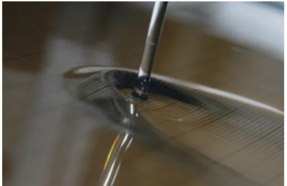
Here we describe a different situation: a jet impinging vertically an inclined surface. In such an experiment, wetting condition appears to be a key parameter. Even at low fluid velocity, the flow structure is not trivial: it involves several distinct regions, with a hydraulic jump near the impact and a curved wetting front (contact line or effective contact line) at larger distance (see Fig. 1). The selection mechanism of their shape and extent is not known, especially for the hydraulic jump. We have investigated these questions for a large range of plate
slope and for different wetting situation.
Figure 1: hydraulic jump and effective
contact line in the total wetting case.
We have also tried to model the results with available theories and in particular the one proposed by Bohr and his team [5]. This one yields a law linking the jump radius RJ to the flow rate Q that reads:
RJ∝ Q
5
8
ν
−38g18 where ν is the kinematic viscosity and g the acceleration due to gravity.To summarize our results, Bohr et al. law well describes the dependence of the jump upstream position upon flow rate with prefactors depending on plate inclination for the total wetting case, and also under partial wetting conditions at large enough flow rate. Surprisingly, in the horizontal limit, the model fails to describe the jump radius accurately. In this last case, we propose a different scaling than the one imagined by Bohr et al.
II Hydraulic jumps on an incline.
A sketch of the experiment is reproduced in Fig. 2. We used two different liquids: silicone oil (viscosity 20 cS, surface tension 20.6 mN/m, density 0.95) and distilled water (viscosity 1 cS, surface tension ~55 mN/m). A jet issued from a vertical tube of internal diameter 3 mm, hits an inclined transparent glass square placed 4 mm below the outlet and of side d = 40 cm.
The plate slope is defined by
the angle α that ranges from 2.5° to 90°.
The camera is placed below the glass plate and pictures are taken through the glass in order to avoid the presence of injector on pictures (see Fig 3). The results can be summarized as follows:Glass plate Camera
Mirror
Tank Gear pump
Nozzle
Gutter Neon light
α
Rtop Rwidth
g
Figure 3: impinging jet on an inclined glass plate observed
across the plate. (a) and (c): total wetting situation for increasing plate slope. (b) and (d): partial wetting case .
α =5° for (a) and (b); α =45° for (c) and (d).
- In partial wetting conditions, a hydraulic jump and a contact line are formed, that can be very close from each other (See Fig 3-d). - In total wetting condition, a similar structure is observed, but with an "effective" contact line that remains static, and stays at larger distance from the jump, surrounded by a liquid film (See Fig 3-c and Fig 1).
- At low plate slope, the hydraulic jump is closed and surrounds completely the impinging jet [10]. Progressively, for larger plate slope the jump opens and has rather a "horseshoe" structure (fig 1, fig.3-c and 3-d). The lower part of the downstream jump has totally disappeared for α close to 30°.
We have investigated
quantitatively the distance between the jet center and the hydraulic jump, varying the wetting conditions. More precisely we measured the upstream jump position with respect to the jet center Rtop and the apparent
"half-width"Rwidth of the jump defined at the jet center altitude (see fig. 3), varying the flow rate Q and the angle α.
Experimental data are plotted in fig. 4 for both wetting condition (partial and total). The results are quite dependent of the wetting conditions:
Under total wetting, the experimental law between radius and flow rate recovers with a surprisingly good agreement the Bohr et al. law linking jump radius RJ and flow rate Q
(devised for a circular hydraulic jump). Furthermore one can observe that the plate slope only changes the prefactor even at very large inclination.
The partial wetting case is more complicated: a power law cannot anymore describe the relation between RJ and Q, and Bohr et al. theory fails to
describe properly this relation. However Bohr et al. law is recovered asymptotically for large flow rate.
From these observations, one can deduce that the contact line plays an important role in the case of partial wetting. Indeed the contact line fixes the boundary condition and can be compared to confinement walls in the case of horizontal circular hydraulic jump. Of course the analogy is non trivial: in our case, the "walls" adapt their position and change with flow rate, which remains to be modeled.
1 10 100
1 10 100
Rtopin function of flow
rate (total wetting)
5 degrees 10 degrees 15 degrees 20 degrees 25 degrees 30 degrees 35 degrees 40 degrees 45 degrees 50 degrees 55 degrees 60 degrees 65 degrees 70 degrees 75 degrees 80 degrees 85 degrees 90 degrees R top (mm) flow rate (cm3 .s-1 ) Q5/8 a. 1 10 100 1 10 100
Rwidthin function of flow
rate (total wetting)
5 degrees 10 degrees 15 degrees 20 degrees 25 degrees 30 degrees 35 degrees 40 degrees 45 degrees 50 degrees 55 degrees 60 degrees 65 degrees 70 degrees 75 degrees 80 degrees 85 degrees 90 degrees R width (mm) flow rate (cm3 .s-1 ) Q5/8 b. 1 10 100 1 10 100
Rtopin function of flow
rate (partial wetting)
2,5 degrees 7,5 degrees 12,5 degrees 17,5 degrees 22,5 degrees 27,5 degrees 32,5 degrees 37,5 degrees 42,5 degrees 47,5 degrees 52,5 degrees 57,5 degrees 62,5 degrees 67,5 degrees 72,5 degrees 77,5 degrees 82,5 degrees 87,5 degrees 90 degrees R top (mm) flow rate (cm3.s-1) Q5/8 c. 1 10 100 1 10 100 2,5 degrees 7,5 degrees 12,5 degrees 17,5 degrees 22,5 degrees 27,5 degrees 32,5 degrees 37,5 degrees 42,5 degrees 47,5 degrees 52,5 degrees 57,5 degrees 62,5 degrees 67,5 degrees 72,5 degrees 77,5 degrees 82,5 degrees 87,5 degrees 90 degrees R width (mm) flow rate (cm3.s-1)
Rwidthin function of flow
rate (partial wetting)
Q5/8
d. Figure 4: Rtop and Rwidthversus flow rate for total wetting situation (a.
and b.) and partial wetting (c. and d.) for α varying from 2.5° to 90°.
This hypothesis is consistent with the observation of an asymptotic regime at large flow rate; indeed we can assume that when the flow rate increases the role of contact line will decreases, as the "walls" become more distant.
We have also investigated the flow lines by injecting bubbles. We observed that the flow is nearly radial inside the hydraulic jump for all the different accessible values of α. This result partially explains the similarities between the behavior of the inclined hydraulic jump and the predictions of Bohr et al. law: inside the jump, the gravity only changes marginally the flow and does not induce a transverse velocity of appreciable strength. This is coherent with our observation of Rwidth (see Fig 4 b. and d.): Rwidth varies only
marginally with respect to the angle α (the effect remains below 10% between 5° and 90°). III Horizontal circular hydraulic jump
In the literature it is known that the properties of a standard hydraulic jump depend critically on a Froude number Fr defined by the ratio between the flow speed and the gravity waves speed
€
Fr = U / gh
where U is the average flow speed, h the height of fluid and g the acceleration due to gravity: Fr is supposed to be larger than one upstream and smaller than one downstream. In the specific case of the circular hydraulic jump, this has never been checked accurately.We have investigated quantitatively this question with a liquid jet impinging a circular glass plate of radius
R
∞. Aconstant Froude number (independent of the flow rate and of the viscosity) was observed at the exit of the hydraulic jump [11].
Modeling the outer flow as a half-Poiseuille flow governed by a balance between hydrostatic pressure and viscous friction leads to a liquid thickness distribution given by:
H (r) = (H
∞ 4+
6
π
νQ
g
ln(
R
∞R
J))
14, (1)where
H
∞ is the liquid thickness at the disk perimeter ("end" of the flow forr = R
∞). For a large enough plate,H
∞4 becomes
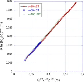
negligible. Combining this profile with a constant Froude number and the conservation the flow rate leads to a new and simple law linking flow rate and jump radius:
R
Jln(
R
∞R
J)
3 8∝ Q
58ν
−38g
18(2)
0 0,005 0,01 0,015 0,02 0,025 0,03 0,035 0,04 0 0,05 0,1 0,15 0,2 ν=20 cST ν=50 cST ν=100 cST R ln (R ∞ /R J ) 3/8 (m) Q5/8 ν-3/8g1/8 (m)Figure 5:Experimental test of eq. (2) for
three different viscosities of silicone oil.
Our results are plotted on Fig 5 and the model fits pretty well our data. In short, we have discovered that Bohr law should involve a logarithmic correction, associated to the selection of a universal critical Froude number at the jump exit.
IV Conclusion
To summarize the results, we have accurately explored the influence of flow rate, plate slope and wetting conditions on inclined hydraulic jump and have evidenced a strong influence of the coupling with the effective contact line. The law given by Bohr well describes the dependence of jump upstream position upon flow rate with prefactors depending on plate inclination in the case of total wetting, but surprisingly the model fails to describe the horizontal case accurately. In this last case, we propose a different scaling than the one imagined by Bohr et al. We propose an interpretation of this scaling in terms of a critical Froude number reached at the jump exit where a matching to a non-trivial outer logarithmic flow has to be made. This model fits well our data and its extension to the incline case is under way. We are also working now on the case of hydrophobic surfaces, where non-trivial de-wetting fronts are formed close to the jet impact.
References
1. J.B. Baonga, H. Louahlia-Gualous, M. Imbert,Applied Thermal Engineering 26, 1125-1138 (2006) 2. S. Van Der Zwaag and J. E. Field, Philosophical Magazine A Pacific Rim 48, 767-777 (1983) 3. I. Tani, J. Phys. Soc. Japan 4, 212–215 (1949)
4. E. Watson, J. Fluid Mech. 20, 481–499 (1964)
5. T. Bohr, P. Dimon and V. Putkaradze, J. Fluid Mech. 254, 635–648 (1993) 6. J. W. M. Bush and J. M. Aristoff, J. Fluid Mech. 489, 229–238 (2003)
7. A. Duchesne, C. Savaro, C. Pirat, L. Lebon and L. Limat, Europhys. Lett, (accepted) (2013) 8. D. Maynes, M. Johnson and B. W. Webb, Phys. Fluids. 23, 052104 (2011)
9. R. P. Kate, P. K. Das and S. Chakraborty, J. Fluid Mech. 573, 247–263 (2007)
10. C. Pirat, L. Lebon, A. Fruleux, J-S. Roche and L. Limat, Phys Rev Letters, 105, 084503 (2010) 11. A. Duchesne, L. Lebon, L. Limat, Universal Froude number in a circular hydraulic jump, preprint