HAL Id: hal-02637958
https://hal.archives-ouvertes.fr/hal-02637958
Submitted on 8 Jun 2020
HAL is a multi-disciplinary open access
archive for the deposit and dissemination of
sci-entific research documents, whether they are
pub-lished or not. The documents may come from
teaching and research institutions in France or
abroad, or from public or private research centers.
L’archive ouverte pluridisciplinaire HAL, est
destinée au dépôt et à la diffusion de documents
scientifiques de niveau recherche, publiés ou non,
émanant des établissements d’enseignement et de
recherche français ou étrangers, des laboratoires
publics ou privés.
Combination of a Wood-Pellet Boiler-Stove with other
Conventional and Renewable Heating System for Space
Heating and Domestic Hot Water within A Passive
House in Belgium
van Long Lê, Arnaud Candaele, Kévin Siau, Jean-Dominique Thomassin,
Thomas Duquesne, Olivier Fontaine de Ghélin
To cite this version:
van Long Lê, Arnaud Candaele, Kévin Siau, Jean-Dominique Thomassin, Thomas Duquesne, et
al..
Combination of a Wood-Pellet Boiler-Stove with other Conventional and Renewable
Heat-ing System for Space HeatHeat-ing and Domestic Hot Water within A Passive House in Belgium.
16th IBPSA International Conference & Exhibition Building Simulation, Sep 2020, Rome, Italy.
�10.26868/25222708.2019.210965�. �hal-02637958�
Combination of a Wood-Pellet Boiler-Stove with other Conventional and Renewable Heating
System for Space Heating and Domestic Hot Water within A Passive House in Belgium
Van Long Le
1, Arnaud Candaele
1, Kévin Siau
1, Jean-Dominique Thomassin
2, Thomas Duquesne
2,
Olivier Fontaine de Ghélin
11
Cenaero, Gosselies, Belgium
2Stûv, Floreffe, Belgium
Abstract
The present study, carried out within the framework of the PCC80 project (PCC80 stands for the Development of a New Generation of Condensing Boiler-Stove with recovery rate over 80 %), aims at investigating the possibility of combining a wood pellet boiler-stove (also called hydro pellet stove) together with other renewable (solar collector) and fossil-fuel (gas-fired boiler) heating devices within a detached single-family house in Belgium. A dynamic thermal simulation approach is used to assess the behaviour and the performance of residential heating systems as well as the occupant thermal comfort in a transient condition. The use of pellet boiler-stove within two different combinations, i.e. one is with only the solar thermal collectors and another one is with both solar collectors and a gas-fired boiler, is compared with the baseline system in which a gas boiler and a series of the solar thermal panels are used for space heating and domestic hot water (DHW) preparation. When using the hydro pellet stove, a fraction of the biomass combustion power is always directly released to its surrounding (i.e. the living-room) by the convection and the radiation, and potentially overheats the room if no space heating is needed. Different control strategies are therefore applied to the pellet-burning device and to the global system for reducing or avoiding this thermal discomfort. Generally, all three studied systems have succeeded in providing the required energy for space heating during the cold season and for making the DHW through the whole-year with the assistance of the solar thermal panels. The combination of gas, pellets and solar elements seem to be the best solution among studied system configurations.
Introduction
In Europe, among different energy consuming sectors, the residential one accounts for about 27 % of the total final energy consumption (Capros et al., 2016). About 79 % of this energy use comes from space heating and hot water demand (Eurostat, 2016). While representing as an important part of the overall final energy demand, about 84 % of heating and cooling is still powered by fossil fuels, which rises the pressure on the EU’s (greenhouse-gas) emission-cut target. Indeed, whereas renewable energies gradually assert their dominance in electricity generation, the heating and cooling sector remain far behind, only 16 % of heating and cooling power across the EU comes from renewable energies such as solar, geothermal resources and biomass. Therefore, without a
major shift towards renewable heating and cooling, the EU will continue to import a large share of fossil fuels, while damaging the environment and putting the health of its citizens at risk (Zervos, Lins, & Muth, 2010).
Amongst different renewable sources, biomass is the most widely used renewable energy for heating today (representing some 90 % of all renewable heating in Europe by 2016). The pellet of compressed wood (or pellet) presents, over other wood-fuels, a set of assets that constitutes one of the fuels of the future. In addition of being a local fuel, whose production and logistics chains have already been structured and professionalised for years, the pellet quality is better and better mastered, thanks to the introduction of standards and quality labels at the international level. Moreover, it can be used in fully automated systems to conciliate user comfort, energy performance and combustion hygiene. These features enable the individual wood-pellet heating systems, over the most suitable systems, to economically meet the new building energy efficiency requirements imposed on the European market.
While the pellet stove always offers an aesthetic pleasing for its user, its service is limited only for space heating which is progressively reduced along with the improvement in building envelope performance. As the demand of direct heating is reduced, the major part of energy supplied by pellet stove must be valorised under other mode than the heat directly released in the room where the device is placed. Indeed, the fact of converting most of the heat produced during the biomass combustion into hot water makes it possible to upgrade this energy in various ways such as distribution in other rooms by radiators or production of DHW, etc.
Within this context, the PCC80 project aims at developing a wood pellet boiler-stove which is aesthetic, user-friendly, efficient and adapted to the specific technical characteristics of dwellings. Such a heating device must satisfy a double objective:
• The stove, on the one hand, offers a broad vision on the flame for the warm and friendly character expected by this kind of products.
• The boiler, on the other hand, must have a high efficiency.
A particular attention of the project will be paid to the technical integration of the hydro pellet stove into the building. The solution will not be designed as a monolithic closed and frozen system but as a
preponderant element of a global and evolutionary heating solution, allowing an optimal valorisation of the different energy sources available in a house. In this respect, the regulation of the system, its opened characteristics and the possibilities of the communication with other energy systems such as solar water heater, heat pump or fossil-fuel boiler, and with the outside world (e.g. weather data) will be a significant part of the development effort.
This study presents the result of the simulation in a transient condition for integrating a hydro pellet stove combined with other renewable (i.e. solar thermal panels) and fossil-fuel (gas boiler) heating devices within a residential building for room heating and DHW preparation. The study assesses the use of the pellet boiler-stove in two different configurations. In the first one, the pellet boiler-stove is combined with solar thermal collectors. In the second one, the pellet-based device is not only combined with the solar collectors, but also with a back-up gas boiler. These two system arrangements are compared with a baseline system in which a gas boiler is combined with a solar water heater. The system modelling and simulation are carried out using the TRNSYS software package (Klein, S.A. et al, 2017). The weather data for Uccle (Belgium) in Typical Meteorological Year Version 2 (TMY2) format is used for the simulation. As presented in the previous work (Le et al., 2018), the operating constraints of the pellet boiler-stove can cause some inconviniences when it is used without a buffer storage tank for space heating and DHW preparation. That is why a central buffer tank will be employed for all three system configurations studied in this paper.
System modelling
System architecture
The hydraulic concepts of the heating systems proposed for the present study can be described using Figure 1. The pellet boiler-stove (hereafter also called boiler-stove or hydro stove) is combined with the solar thermal collectors for charging the buffer storage tank. The heat storage is charged by solar energy as long as the temperature difference between the collector outlet and the bottom part of the storage tank is above a set value. The pellet combustion is the principal heat source supplying almost the energy required for room heating and DHW production over the heating season (between October and May) defined in the weather data file. Outside of this time when the space heating is no longer needed and the solar irradiation is high, the hydro stove will serve as a back-up boiler to the solar water heater, almost two thirds of the energy required for making hot water comes from the solar irradiation. Different control strategies through the heating and cooling seasons will be applied to the boiler-stove for avoiding the potential overheating caused by device’s usage especially during summer.
As many pellet boilers being installed are retrofitted into existing hydronic heating systems that have one or more fossil-fuel boiler, an optional connection to a gas boiler is also considered in this paper. This scenario can be useful. Throughout the cold season, the pellet boiler can serve as
the “base load” heat source, often supplying more than 90 % of the seasonal heating energy required. The existing boiler is retained to meet peak load or to provide all heat input to the building if the pellet boiler-stove is down for maintenance or service issues. The boiler-stove would operate as the fixed stage 1 boiler. The single existing gas boiler would operate as stage 2 boiler. From end of May to beginning of October, only solar collector and gas boiler (serving as a back-up boiler) will be used for charging the storage tank.
The combination between a gas boiler and solar thermal panels is also considered as the baseline system to be compared with the two other system configurations. The three system arrangements considered in this study are: • System 1: Hydro pellet stove + solar collectors • System 2: Hydro pellet stove + gas boiler + solar
collectors
• System 3: Gas boiler + solar collectors
Figure 1: System architecture
As an amount of direct heat is always released by the boiler-stove to its surrounding when operating, a smaller radiator will be installed in the living-room for system 1 and 2 compared to the system 3.
Figure 2: DHW load profile for 7 days with a timestep of 12 mins
For all three systems above, the cold water goes through the coiled tube heat exchanger inside the buffer tank to increase the temperature. The hot water exiting the coil will then be mixed with the cold water to yield hot water at the desired temperature (i.e. 45°C for this study). The
load profile of hot water (cf. Figure 2) is in this work created using DHWcal program (Jordan & Vajen, 2005). The space heating loop is connected directly to the buffer tank and controlled by the room thermostat located in the living-room (cf. Figure 1). For the present study, only the hydronic radiators are used to warm up the rooms. Between October and May, the hot water from the buffer tank is automatically pushed through the radiators when the air temperature in the living-room is below its scheduled setpoint value. The mass flow rate of hot water going into the radiators is adjusted by the thermostatic valve installed on each radiator. The hot water from the buffer tank is mixed with the water coming back from the radiators to reach its expected supply temperature. This temperature value is not constant but reset over time depending on the outdoor air temperature as presented in Figure 3.
Figure 3: Outdoor air temperature reset for space heating loop
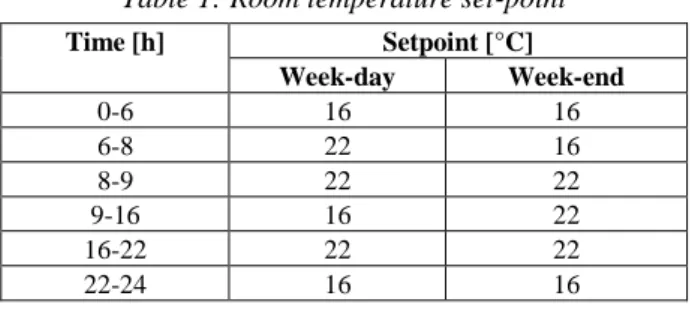
The room temperature setpoint is scheduled for the specified time intervals during week-days and week-ends as found in Table 1.
Table 1: Room temperature set-point
Time [h] Setpoint [°C] Week-day Week-end 0-6 16 16 6-8 22 16 8-9 22 22 9-16 16 22 16-22 22 22 22-24 16 16 Building model
The studied house is simulated using the multi-zones building model of TRNSYS (i.e. Type 56). The building is a typical Belgian detached (4 facades) single-family (5 persons) house whose benchmark geometry has been established by Massart and De Herde (2010). The building is also used and well described in the study of Georges, Skreiberg, and Novakovic (2014). The house has a total floor area of 152 m2. Its envelope presents a
protected volume of 420 m3, 360 m2 of opaque surfaces
and 35 m2 of windows. The house’s internal organization
is displayed in Figure 4:
• The building is partitioned into two floors connected by a corridor (zone 2).
• Each zone is modelled by only one thermal node, including zone 2 spreading on both floors.
• The living-room (zone 1) is oriented towards the South and contains the pellet boiler-stove.
• No thermal bridge is considered.
• The house is highly insulated and considered with a performance level of the passive house.
• A mechanical ventilation with heat recovery is installed for the house.
• No ground coupled heat exchanger is taken into account for the present study.
• Some other features such as solar protection, natural intensive ventilation are also considered for the simulation as described in the work of (Massart & De Herde, 2010).
Figure 4: Sketches of ground and first floor of the building: kitchen coupled living-room (1), corridor (2),
laundry (3), office (4), bedrooms (5, 6, 8, 9) and bathrooms (7,10)
A summary of the main building properties, i.e. thickness and heat loss coefficients (U-value) of the corresponding walls, is given in Table 2.
Table 2: Building properties
Wall Thickness [m] U-value [W/m2-K]
External wall 0.465 0.114 Adjacent wall 0.13 2.963 Adjacent ceiling 0.248 1.873 Roof 0.419 0.111 Ground slab 0.495 0.155 Glazing/window - 0.81
To take into account the ventilation and the air circulation inside the house, TRNFLOW (Weber, Koschenz, Dorer, Hiller, & Holst, 2003) is used. This module is coupled to TRNSYS allowing to model simultaneously the balanced whole-house mechanical ventilation by the air-intake within the living-room and the bedrooms and the extraction of the air from wet rooms (bathroom, laundry, toilet), but also to integrate different doors between the rooms, and to consider the house tightness by means of an appropriated mathematical model. For the present study, the living-room door is always opened while the doors of other rooms (bedrooms, office and bathroom) are closed. The heat recovery of mechanical ventilation is bypassed when the following conditions are reached:
• Throughout the cooling season, when the air temperature of the living-room is simultaneously greater than its setpoint and the outdoor temperature • Between October and May, when the stale air
temperature is greater than 23 °C and the outdoor temperature at the same time.
Boiler-Stove model
The dynamic boiler-stove model in this study has been developed on the basis of an existing pellet boiler-stove model (Nordlander, 2003) with the appropriate adaptations and modifications. The model is developed in the C++ programming language and implemented as a non-standard component in TRNSYS environment. Being similar to the existing model of Nordlander (2003), the device operation has two-steps start phase, a burning phase and a stop phase lasting for a certain time after the pellet feeder has been turned off. The description of the start and stop phases as well as the minimum operating and cooling time of the heating device are given in Table 3. The maximum power output of pellet boiler-stove studied in the present work is of 9.37 kW (provided by Stûv). It is possible to scale the device power output down to 30 percent of its maximum value.
Table 3: Boiler-stove characteristics
Pre-set duration
Description
dtsta1
Duration between start signal and first flame vision of the stove, no combustion power is assumed.
dtsta2 Duration in which the stove operates with a
combustion power Pcmbsta (e.g. Pcmbsta = Pcmb,min)
dtfstp
After stop sign, duration in which the stove continues to generate a decreasing power.
dtcool, min
In addition to stop phase duration, the minimum time before the device can be switched on again.
dtop,min Minimum operating time between obtaining
first flame and the stop sign
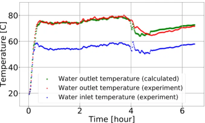
The numerical model of hydro pellet stove is calibrated by means of an optimization process which minimises the difference between the result obtained from the simulation and the experimental data. The optimization, performed by GenOpt program (Wetter, 2001), is used with the GPS (Global Pattern Search) Hooke-Jeeves method. The cost function, CF, is defined as follows:
(
)
2 2, , ( )
wo cal wo ex cal ex
CF= T −T + Q −Q (1)
Where
Two,cal and Two,ex are the calculated and experimental
temperatures of water exiting the hydro stove, respectively.
cal
Q and Qex are the calculated and experimental values of heat rate transferred to the water and the boiler-stove’s surrounding, respectively.
The difference between the numerical calculation and the experimental values of water outlet temperature is shown in Figure 5. The figure shows a good agreement between the simulation results and the experimental data.
Figure 5: Experiment vs simulation for model calibration
Buffer tank, solar collector and gas boiler
The hot water accumulator is simulated using Type 534 of TESS (Thermal Energy System Specialists) library. This is the model of a constant volume storage tank with immersed heat exchangers. The tank volume is 0.6 m³. The model accounts for the thermal stratification by breaking the tank into a user specified number of isothermal nodes (6 for the present work). The storage tank has two immersed heat exchangers, one for the solar circuit and another one for heating up the domestic water. The heat exchanger of the solar circuit is placed at the bottom of the tank. The immersed DHW exchanger has its outlet at the top of the tank to extract the water as hot as possible. The hydro pellet stove and the gas boiler charge the heat storage at the top of the tank.
The thermal solar collectors are simulated using Type 539 (TESS library) which models a flat plate solar collector. The effects of the collector mass on its performance is considered by this model. The thermal performance of the total collector array is determined by the number of modules in series and the characteristics of each module. The collector performance is calculated using the result from a standard collector efficiency test.
The differential controller, in conjunction with the collector and buffer tank sensors, determines when the pump should be activated to send the heat transfer fluid through the collector. The differential controller measures the temperature difference between the water leaving the solar collector and the water in the bottom part of the storage tank. When the water in the collector is about 10 °C warmer than the water in the storage tank, the pump is turned on by the controller. When the temperature difference drops to about 2 °C, the pump is turned off. In this way, the water always gains heat from the collector when the pump operates.
The gas boiler is only used in the system 2 and 3 for the present study. It is simulated using Type 751 of TESS library which models a simple boiler whose efficiency is read from an external data (TRNSYS default external data is used in this paper). The rated capacity of the boiler is assumed to be 10 kW. The boiler power output is scalable down to 20 % of its maximum value.
When being used together with pellet boiler-stove and solar collectors in the system 2, the gas boiler is turned on when the water temperature at the top of the storage tank
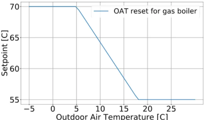
is lower than 55 °C and turned off if the temperature is higher than 60 °C. Without pellet boiler-stove in the global system (the configuration 3), the gas boiler is the principal heat source for supplying almost the heating seasonal energy required and will be turned on if water temperature inside tank is below the temperature setpoint and turned off if the water temperature is 5 °C higher than the setpoint. During the cooling season, the setpoint value is constantly set to 55 °C while its value will be reset depending on the outdoor air temperature over the heating season as shown in Figure 6.
Figure 6: Outdoor air temperature reset for gas boiler
Hydronic radiator
The radiator is simulated using the first order radiator model (i.e. the total radiator heat capacitance is concentrated at the exhaust node) as described by Holst (1996). The dynamic radiator model is developed using the C++ programming language and implemented in the TRNSYS environment as a non-standard component. The basic equations for the radiator model are given as below. The heat balance equation:
, , ( ) n r wo lm w w wi wo r n lm n C dT T M Cp T T Q dt T − = + (2) The logarithmic mean temperature difference:
wi wo lm wi amb wo amb T T T T T ln T T − = − − (3)
The lumped radiator capacitance of fluid and metal: r w w met met
C =m Cp +m Cp (4) The subscripts w, met, r, and n denote water, metal, radiator and nominal value, respectively. The superscript
n is the radiator exponent, i.e. the values that were used to
define a radiator’s nominal heating capacity.
The emitted radiator power is transferred to the room by the convection and the radiation. Knowing the radiative fraction of the emitted power at nominal operating condition (sn), the radiative fraction at other operating
condition (s), is obtained by the following equation:
4 4 4 4 , , ( ) ( ) [( ) ( ) ] K K n amb lm amb n K K lm amb lm n amb lm n s T T T s T T T T T + − = + − (5)
The ambient temperature, Tamb, in the equation above is in
Kelvin (K).
Control strategies
This section describes the control strategies of hydro pellet stove used in the system 1 and 2. Regardless the system configuration, the boiler-stove ON/OFF is driven using a differential controller with a hysteresis depending on the water temperature at the top of the storage tank: • If the temperature is lower than the setpoint, the
boiler-stove is on.
• If the temperature is 10 °C higher than the setpoint, the boiler-stove is off.
Table 4: Scheduled setpoint for boiler-stove ON/OFF
Time interval [h] Setpoint [°C] Week-day Week-end 0 – 5 TL TL 5-7 TH TL 7-9 TH TH 9-15 TL TH 15-21 TH TH 21-22 TL TH 22-24 TL TL
For maximizing the vision on the flame of the stove and avoiding unnecessary overheating during night-time and inoccupancy day-time, the hydro pellet stove in the system 1 and 2 is preferred to work over specified time intervals between 5 am and 10 pm between October and May. To do that two setpoint levels (high - H and low - L) are scheduled for the water temperature at the top of the tank as found in Table 4. In addition to the scheduled setpoints, the values of TH, varying between 70 °C and 45
°C, will be reset as a function of the outdoor air temperature as shown in Figure 7. The value of TL in the
Table 4 is kept constant at 45 °C.
Figure 7: Outdoor air reset control
During the warm season, no space heating is needed. If a gas boiler is available in the system, the pellet boiler stove will be turned off for the whole period (as in the configuration 2). The back-up service to the solar water heater will be taken by the gas boiler. If there is no gas-fired device in the system (configuration 1), the hydro pellet stove will be commanded to serve as a back-up device for the solar water heater. Two fixed setpoint levels are scheduled to promote the pellet-burning device to work between midnight and 6 am. During this period, the pellet device will be commanded to operate if the water temperature at the top of the tank is lower than 60 °C.
From 6 am to midnight, the boiler-stove will be used if the water temperature inside tank falls below 45 °C. A hysteresis of 10 °C is applied for controlling the device ON/OFF.
Results and discussions
The results presented in this paper are obtained from the dynamic simulation performed through the whole year with a timestep of 6 mins for all three configurations. As some numerical elements (i.e. Type 56 walls) of the system modelling are always initialized with a constant value, a warm-up period is then necessary to suppress the impact of initial conditions (Delcroix, Kummert, Daoud, & Hiller, 2012). In this study, an extra week at the beginning of the simulation is run as a warm-up time. This one week should not be taken into the final simulation result.
Figure 8: Operations of pellet boiler-stove and gas boiler for the three systems
Figure 8 presents the power outputs of the pellet boiler-stove and the gas boiler for the system 1 (in the bottom of figure) and 2 (in the top of the figure) as well as the useful energy gained by solar collector fluid (in the middle of the figure). The solar gain is the same for all three different system arrangements. In the system 1, only hydro pellet stove (in blue) is available. This machine is commanded to operate throughout the whole year for heating up the house and making the DHW. A smaller operating frequency during hot season (from end of May to beginning of October) is observed for these heating devices since an important part of energy required for preparing the DHW is provided by solar thermal system and no space heating is necessary during this season. In the system 2, both hydro pellet stove and gas boiler are available. The pellet boiler-stove (in blue) is not ordered to run during the hot season but only for the period of cold weather when room heating is needed. The gas boiler (in red) is used during heating season only for meeting peak loads or when the pellet-burning device cannot be switched on from off situation due to its operational constraint (i.e. constraint on the minimum required cooling time). Within cooling season, the gas-fired boiler is used as a “back-up” solution to solar thermal system for making DHW.
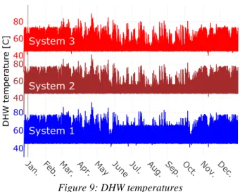
Figure 9: DHW temperatures
For all three systems, the DHW with a wanted temperature of 45 °C is almost produced for the whole year as found in Figure 9. The best system in terms of DHW preparation is the second one, only one moment through the whole year, the temperature of required domestic water cannot be reached 45 °C. As the pellet boiler-stove in the system 1 is preferably shifted to operate between midnight and 6 am for advoiding the daytime overheating during the cooling season, the temperature is found below the wanted value when the hot water is taken at several moments during this period. During the cold period, the system 1 works as good as the system 2 for producing the domestic hot water.
Figure 10: Living-room air temperatures
Figure 10 compares the air temperature (in smoothed values) of the living-room (dashed lines) when using different heating systems 1 to 3. The living-room air temperature varies from about 18 °C, during night at the coldest moments of winter, to a maximum of about 33 °C in summer when the outdoor temperature (in brown) is about 30 °C. Over winter, the “smoothed” air temperatures go from 18 °C to 22 °C. Close to the so-called cooling season (end of May to beginning of October), the air temperature of zone 1 increases slightly to between 22 °C and 26 °C. A small overheating is observed for the systems (1 and 2) using a pellet-burning device compared to the baseline system with a gas boiler for this period. The frequency of overheating is greater during the cooling season, but its intensity remains maximum around 1 °C. Since the hydro pellet stove is, in
the system 2, replaced by a gas boiler as the solar domestic hot water (SDHW) back-up in this period, the air temperature is identical for the system 2 and 3.
The impact of the boiler-stove’s use to the house overheating is presented (for a 4-days period in summer, from 21/07 to 24/07, and winter, from 10/01 to 13/01) in Figure 11. In Winter, the amount of direct heat released when using pellet-based device contributes to the energy required for heating up the room. The living-room air temperature is identical (over observed period in the lower part of Figure 11) for the system 1 than the system 3. Indeed, the applied control strategies for hydro pellet stove have a good effect to promote the device to work when the space heating is needed. The working moment and cycle length are quite similar for the hydro stove (in system 1) than the gas boiler (in system 3) even with two different control strategies. In summer, no space heating is needed, any thermal gain from direct heat when using boiler-stove will create the overheating. Its operation is therefore preferably brought to between midnight and 6 am, when the living-room is not occupied and the outdoor air temperature decreases. As shown in the upper part of Figure 11, the overheating (caused by the use of the boiler-stove) in the living-room is only observed just after midnight. There is no difference in bedroom air temperature between system 1 and 3. The same legends (displayed in the upper part) are shared for the two parts of Figure 11.
Figure 11: Impact of pellet boiler-stove’s use on room air temperatures in summer (above) and winter (below)
Figure 12: Operation of pellet boiler-stove in summer (above) and winter (below)
The performance, working time and cycle length of the pellet device are shown (for a 3-days period in summer, from 20/07 to 22/07, and winter, from 10/01 to 12/01) in Figure 12. During summer the pellet boiler-stove is commanded to run for often only once a day or once every
two days with working cyles much shorter than that in winter. Regarding the boiler-stove performance, about 90 % of the pellet combustion is converted into the water and the direct heat which increases the room temperature, only 10 % of combustion energy is lost through the flue gas. The combustion losses by unburned gas (CO) and in unburned components in residues are very small and neglected in this study. As the model calibration of the boiler-stove is performed using the experimental data at the early stage of the product development, only 65 to 67 % of the pellet combustion power is transferred to the water, more than 20 % of this energy is still converted into the room direct heating. In the final product, at least 80 % of the combustion power must be transferred to the water.
Figure 13: Energy consumption and solar gain
Regarding energy consumption for comparing different systems, only required combustion energy for gas boiler and pellet boiler-stove are considered. The parasitic energy consumption, e.g. electricity consumption, required for space heating and DHW preparation are not considered. The largest energy in thermal kWh is consumed by the system 3 followed by the system 1 and the lowest one is observed for the combination of pellets, gas and solar. The useful solar energy gained by collector fluid (brown curve in Figure 13) is the same for all three configurations.
Currently, several EU State members grant the “Renewable Heat Incentive” for the pellet-burning products which makes it more competitive in terms of economic benefit to the fossil-fuel boiler whose utilisation is harmful for the environment and the human health.
Conclusion
The present study performs the dynamic simulation for integrating a wood pellet boiler-stove combined with solar thermal panels in two different system configurations, i.e. with and without gas-fired boiler, for heating up the house and making DHW. These system arrangements are also compared with a baseline system in which only gas boiler is used for space heating during the cold season and serving as the SDHW back-up in the warm season (high-irradiance period). Several conclusions can be drawn as:
• The hydro pellet stove brings not only the aesthetic advantage to the users, but also the efficiency in making DHW and heating up their dwelling.
• The pellet boiler-stove could be a good renewable alternative-solution for the fossil-fuel boiler.
• The use of hydro stove can cause thermal discomfort to the user in terms of room overheating especially in summer. The discomfort is reduced by combining the pellet-burning device with other renewable or even fossil-fuel heating devices and by the sophisticated control strategies.
• The modification in hydraulic concept and the application of different control strategies in the present paper has a good effect for reducing or avoiding the issues caused by operating constraints of the pellet device as described in the previous work (Le et al., 2018).
• The combination of pellet, gas and solar elements seems to be the best solution when considering simultaneously the environmental-friendliness, the thermal comfort and the energy consumption in thermal kWh.
Further work should focus on a detail eco-environmental analysis of different system configurations to evaluate more precisely the potential of using a hydro pellet stove as an alternative device for conventional fossil-fuel boiler in the household sector. The extreme weather conditions and other building typologies should also be considered. The study will be useful not only for the boiler-stove manufacturer to identify the best use cases of pellet-burning device and the necessary improvements for global system efficiency, but also to help the government in making the right policies for promoting the use of renewable energies, e.g. renewable heating incentives.
Acknowledgement
The authors would like to thank the Walloon Public Service for funding this research. The authors would like to thank Dr. Charlotte Marguerite (Senior Research Engineer at Cenaero) for constructive criticism of the manuscript.
Nomenclatures
C [kJ/K] thermal mass CF [-] cost function Cp [kJ/kg-K] specific heat m [kg] massM [kg/h] mass flow rate
Q [kJ/h] heat power
T [°C] temperature
References
Capros, P., De Vita, A., Tasios, N., Siskos, P., Kannavou, M., Petropoulos, A., … Kesting, M. (2016). EU
Reference Scenario 2016: Energy, Transport and
GHG emissions trends to 2050. European Commission. http://doi.org/10.2833/9127
Delcroix, B., Kummert, M., Daoud, A., & Hiller, M. (2012). Conduction transfer functions in TRNSYS multizone building model: Current implementation, limitations and possible improvements. In SimBuild (pp. 219–226).
Eurostat. (2016). Eurostat - Statistics explained. Energy consumption in households. Retrieved January 28, 2019, from https://ec.europa.eu/eurostat/statistics-explained/index.php/Energy_consumption_in_house holds#cite_note-1
Georges, L., Skreiberg, Ø., & Novakovic, V. (2014). On the proper integration of wood stoves in passive houses under cold climates. Energy and Buildings, 72, 87–95. http://doi.org/10.1016/j.enbuild.2013.12.023 Holst, S. (1996). TRNSYS - Models for Radiator Heating
Systems.
Jordan, U., & Vajen, K. (2005). DHWcalc: Program to generate Domestic Hot Water profiles with statistical means for user defined conditions. In Solar World
Congress 2005: Bringing Water to the World (Vol. 3,
pp. 1525–1530). Retrieved from www.solar.uni-kassel.de.
Klein, S.A. et al. (2017). TRNSYS 18: A Transient System Simulation Program. Solar Energy Laboratory, University of Wisconsin. Retrieved from http://sel.me.wisc.edu/trnsys
Le, V. L., Candaele, A., Siau, K., Thomassin, J.-D., Duquesne, T., Fontaine De Ghélin, O., … Gosselies, B. (2018). Dynamic modelling and control strategy of a heating system based on wood pellet boiler-stove. In
System Simulation in Buildings 2018.
Massart, C., & De Herde, A. (2010). Conception de maisons neuves durables.
Nordlander, S. (2003). TRNSYS model for Type 210 Pellet
stove with liquid heat exchanger: Documentation of model and parameter identification. Solar Energy Research Center.
Weber, A., Koschenz, M., Dorer, V., Hiller, M., & Holst, S. (2003). TRNFLOW, a new tool for the modelling of heat, air and pollutant transport in buildings within TRNSYS. 8th International IBPSA Conference. Wetter, M. (2001). GenOpt - A Generic Optimization
Program. Seventh International IBPSA Conference. http://doi.org/10.2172/962948
Zervos, A., Lins, C., & Muth, J. (2010). RE-thinking 2050: a 100% renewable energy vision for the
European Union. Erec.
http://doi.org/https://www2.warwick.ac.uk/fac/soc/pa is/research/researchcentres/csgr/green/foresight/energ yenvironment/2010_erec_rethinkhing_2050.pdf