Publisher’s version / Version de l'éditeur:
BEST 3 2012: Building Enclosure Science and Technology Conference Proceedings, pp. 1-6, 2012-06-28
READ THESE TERMS AND CONDITIONS CAREFULLY BEFORE USING THIS WEBSITE. https://nrc-publications.canada.ca/eng/copyright
Vous avez des questions? Nous pouvons vous aider. Pour communiquer directement avec un auteur, consultez la
première page de la revue dans laquelle son article a été publié afin de trouver ses coordonnées. Si vous n’arrivez pas à les repérer, communiquez avec nous à [email protected].
Questions? Contact the NRC Publications Archive team at
[email protected]. If you wish to email the authors directly, please see the first page of the publication for their contact information.
NRC Publications Archive
Archives des publications du CNRC
This publication could be one of several versions: author’s original, accepted manuscript or the publisher’s version. / La version de cette publication peut être l’une des suivantes : la version prépublication de l’auteur, la version acceptée du manuscrit ou la version de l’éditeur.
Access and use of this website and the material on it are subject to the Terms and Conditions set forth at
The effect of window-wall interface details on window condensation
potential
Maref, W.; Van Den Bossche, N.; Armstrong, M.; Lacasse, M. A.; Elmahdy,
H.; Glazer, R.
https://publications-cnrc.canada.ca/fra/droits
L’accès à ce site Web et l’utilisation de son contenu sont assujettis aux conditions présentées dans le site
LISEZ CES CONDITIONS ATTENTIVEMENT AVANT D’UTILISER CE SITE WEB.
NRC Publications Record / Notice d'Archives des publications de CNRC:
https://nrc-publications.canada.ca/eng/view/object/?id=60e85cc5-3cf7-47e0-830c-d3129759d643 https://publications-cnrc.canada.ca/fra/voir/objet/?id=60e85cc5-3cf7-47e0-830c-d3129759d643
THE EFFECT OF WINDOW-WALL INTERFACE DETAILS
ON WINDOW CONDENSATION POTENTIAL
W. Maref
1, N. Van Den Bossche
2, M. Armstrong
1, M.A. Lacasse
1, H. Elmahdy
1and
R. Glazer
11-National Research Council Canada, Institute for Research in Construction, Ottawa, ON, Canada
2-Ghent University, Department of Architecture and Urban Planning, Ghent, Belgium
Considering all building components, windows typically have the lowest surface temperature, and will consequently be the primary location for interior surface condensation. Those surface temperatures can easily be calculated using thermal finite-element-models (FEM), and there is an ISO standard with guidelines for condensation risk assessment. However, both the FEM-simulations as the ISO standard generally omit the effect of air flows in and around window frames. When cold air is drawn into the construction, the airflow might cool down specific components of the window-wall interface depending on the location of the airflow path. Consequently, the current evaluation method for condensation risk assessment based on FEM-simulations might underestimate the actual risk. There is a need to determine if interface details become more susceptible for surface condensation due to pressure differences over the component. This paper reports on a laboratory evaluation of condensation risk assessment in a hotbox, with varying pressure differences and the introduction of deficiencies. It was concluded that the effect of the type of insulation in the window-wall interface was very low for isobaric boundary conditions, whereas it has a significant effect when pressure differences are applied. A full paper on this topic has been accepted for publication by the Journal of Building Physics.
INTRODUCTION
The condensation risk on specific components of the window-wall interface will be determined by the thermal properties and behaviour of the element and the boundary conditions it is subjected to. Hence it is necessary to normalize the performance of a specific component in order to use the results for risk assessment for different climates and interior conditions. The “Temperature Index” ( I ) of a component is a non-dimensional index which represents the interior surface temperature relative to the interior and exterior air temperatures. It can be determined based on the following relationship provided in EN ISO 13788 [EN ISO 13788, 2001]:
I = (Ts–To) / (Ti– To) (1)
where Ti and To are the indoor and outdoor air temperatures, and Ts is the average room-side
surface temperature. In this paper the temperature index is determined in a guarded hot-box experiment, in which a specimen was subjected to temperature differentials as well as pressure differences. The CSA A440.2 [CSA, 2004] test method for determining condensation potential on windows was followed, but with two significant exceptions: the pressure difference across the specimen was adjusted to 20 and 40 Pa and at levels in excess of that required in the standard (i.e. 0 ± 5 Pa) and deficiencies were introduced at the wall-window interface. Surface temperature conditions on either side of the window and on specified window components (e.g. glazing; frame at sill and at jambs) were continuously monitored with a set of 40 thermocouples: 20 on the exterior and 20 on the interior of the specimen. Thermocouples were also placed within the cavity between the window frame and window opening. Thermocouple temperature measurements were made to an accuracy of ± 0.5 °C. The temperature differential for the tests
was set at 50°C ± 1.5°C and the temperature sensor measurements were recorded once steady state conditions were achieved following a period of 15 minutes in these conditions (room side: 20°C, exterior: –30°C).
EXPERIMENTAL SETUP
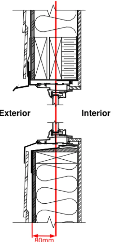
The nominal size of the test frame incorporating the wall-window interface was 1.22-m wide by 2.44-m high, and framed with 51 by 152-mm Spruce-Pine-Fir lumber. The test assembly was intended to be representative of typical North American wood frame construction practice. The exterior cladding of the assembly was hardboard wood composite siding, installed in accordance with current building practice, and directly to the sheathing membrane (Weather Resistive Barrier-WRB-spun bonded polyolefin). The membrane overlays an oriented strand board (OSB; 11-mm) wood sheathing panel affixed over the wood frame. Glass fibre batt type insulation was placed in the stud cavities adjacent to the window opening and the interior finish was gypsum board (12.7-mm). A fixed (non-operable) non-flanged PVC window (610-mm by 1220-mm) was centered vertically within the specimen. The window was installed with the glazing aligned with the plane of thermal resistance of the wall. Figure 1 provides installation details of a box window incorporating pan flashing, sloped sill, up-stand and related details that help promote drainage of water from the windowsill if subjected to inadvertent water entry. Figure 1 shows the location of the plane of thermal resistance of the wall in relation to that of a box window installed along the same plane.
Figure 1. Installation detail for box window
Exterior Interior
Figure 2. Instrumentation of the sample in the guarded hot-box with thermocouples and pressure sensors.
To analyze the effect of different installation methods, the space between the window frame and wood frame wall was left empty (Test set 1), was filled with glass fibre insulation (Test set 2) or spray-in-place polyurethane foam (SPF) (Test set 3). Finally, given the interest in using installation details that included a sill pan, thought was given to possible paths of air leakage through the assembly at the sill and the type of deficiencies that might arise at these locations due to improper installation of components or premature failure of seal components. The introduction of two deficiencies at the wall-window interface provided a means to evaluate whether air leakage across different components of the window assembly caused condensation to form on the warm side of the wall assembly when leakage was induced in the test assembly. A first deficiency was located at the exterior of the wall-window interface and at the juncture of the cladding and window frame at the lower extreme corner of the window, whereas the second one was situated at the interior of the assembly at the interface between the window frame and the interior finish but located at the upper most and opposite corner of the window assembly.
RESULTS
For each of the three installation methods, tests were done with and without deficiencies, at 0Pa, 20Pa and 40Pa, which renders a total of 18 tests. This section only reports and anayses the results of a 3 tests: the three installation methods are compared for the situation where a pressure
Figure 3. temperature index in the window-wall cavity and at the interior surface of the window. The figure clearly indicates that the interior surface temperature of the IGU is very similar for the different installation methods. Due to thermal stratification in the cavity of the IGU, the lowest temperature indexes can be found at the window sill, and the spacer of the IGU causes an additional temperature drop which is most pronounced in the corners. In general, the surface temperature of the IGU proved to be insensitive for the installation method, the presence of deficiencies, as the pressure difference over the sample.
The surface temperature of the window frame is more affected by the cold air drawn into the construction due to the pressure difference. Again, the lowest temperatures can be found at the sill, but the installation with SPF results in surface temperatures which are significantly higher compared to those for installation without insulation. The use of mineral fibre reduces the effect of air flows through the construction but cannot block it completely. It should be noted that the analyses shows two major pathways for air flows: first of all along the deficiencies introduced at the window-wall interface, but secondly – and more surprisingly – there were air flows through the window frame itself which had a significant effect on the surface temperatures of the frame. A closer examination of several samples of the window typology used in this study revealed imperfections at the mitre joint of the welded vinyl frame. The mitre joint was chamfered after welding, but in some instances it apparently was cut off, thereby revealing a small opening (slit) at the exterior corners of the window frame. As well it was observed that at the top and bottom side of the window there were minor perforations caused by staples; these staples were used to secure the wood protection strapping in place during transport of windows. It was also evident that there were no weep holes at the bottom side of the window (contrary to good practice). In general the windows were poorly fabricated and several deficiencies were present in the frame specifically at the corners both inside and outside. These deficiencies rendered it possible for
cold air to enter the frame from the outside between the window frame and the wood stud wall, and permit air to leave the frame at the interior at joints located at the glazing stops.
Finally, the temperature index in the interface between the frame and wood frame wall was also recorded. At the jamb, a vertical gradient was recorded for all configurations, with and without pressure difference. Figure 3 clearly shows that the temperatures rises going from no insulation over mineral fibre to SPF, whereas the thermal gradient declines. Very low temperature indexes are evident for the installation without insulation, where the cavity is open to the outside by way of the drainage opening between the window sill and subsill, and the deficiencies introduced in the corners. Although this solution promotes the evacuation of rain water that might infiltrate, the installation without insulation is sensitive to a temperature drop when a pressure difference is applied. For more details see Maref (Maref & al, 2011).
CONCLUSIONS
The temperatures on the insulated glazing unit show a significant vertical thermal gradient, and the spacer around the perimeter acts as an additional thermal bridge causing low surface temperatures in all configurations. However, the IGU is not very sensitive to the changes occurring inside the cavity between the window frame and the rough opening: the effect was limited to about 1°C and was likely caused by imperfections in the window frame. The box window used in the measurements was – although typical for North-American construction practice - of lesser quality, as several cracks and deficiencies in the window frame, in certain instances, directly affected results. Even for the installation with SPF without deficiencies it was observed that the surface temperature on the window profile dropped 1°C, possibly caused by insufficient airtightness of the window frame.
There are significant differences between trends in mean values and extreme values. Very local effects and deficiencies may have an important effect and will determine the primary location for surface condensation. By insulating the cavity between window frame and wall, the temperature index increases about 0.02 compared to an empty cavity. Pressure differences introduce significant reductions in temperature indexes (between 0.02 and 0.07), which are partially omitted by installing insulation. Convective air transport around the window was partly retarded by the installation of glass fibre insulation. Only the use of spray foam insulation provided a seal to the perimeter thereby avoiding cooling of the window profile.
The analysis of the results shows that an accurate condensation risk assessment should consider the effect of air flows in the window and the window-wall interface. Consequently the full paper presents a number of changes to the methodology of EN ISO 13788:2001, in order to apply the algorithm to window frames, and an additional safety factor is introduced for the minimum temperature index, depending on the type of window-wall interface.
ACKNOWLEDGEMENTS
The authors wish to thank the Canada Mortgage and Housing Corporation for partial funding of the project and acknowledge the contributions of Mr. Silvio Plescia, Senior Researcher, Canada Mortgage and Housing Corporation to this paper.
REFERENCES
CSA 2004. Energy performance of windows and other fenestration systems/User guide to CSA A440.2-04. Canadian Standards Association, Mississauga, Canada, 142 p.
EN ISO 13788: 2001. Hygrothermal performance of building components and building elements – Internal surface temperature to avoid critical surface humidity and interstitial condensation – Calculation methods. CEN, Brussels, Belgium.
W. Maref, N. Van Den Bossche, M. Armstrong, M.A. Lacasse, H. Elmahdyand R. Glazer , 2011, “Condensation Risk Assessment in Box Windows: The effect of The Window-Wall Interface”, in press in International Journal of Building Physics, 2011.