Publisher’s version / Version de l'éditeur:
Proceedings of the 31st Symposium on Ultrasonic Electronics, 2010-12-26
READ THESE TERMS AND CONDITIONS CAREFULLY BEFORE USING THIS WEBSITE. https://nrc-publications.canada.ca/eng/copyright
Vous avez des questions? Nous pouvons vous aider. Pour communiquer directement avec un auteur, consultez la
première page de la revue dans laquelle son article a été publié afin de trouver ses coordonnées. Si vous n’arrivez pas à les repérer, communiquez avec nous à [email protected].
Questions? Contact the NRC Publications Archive team at
[email protected]. If you wish to email the authors directly, please see the first page of the publication for their contact information.
NRC Publications Archive
Archives des publications du CNRC
This publication could be one of several versions: author’s original, accepted manuscript or the publisher’s version. / La version de cette publication peut être l’une des suivantes : la version prépublication de l’auteur, la version acceptée du manuscrit ou la version de l’éditeur.
Access and use of this website and the material on it are subject to the Terms and Conditions set forth at
Noncontact ultrasonic sensing using induction based method and
integrated piezoelectric ultrasonic transducer
Murayama, Riichi; Kobayashi, Makiko; Wu, Kuo-Ting; Jen, Cheng-Kuei
https://publications-cnrc.canada.ca/fra/droits
L’accès à ce site Web et l’utilisation de son contenu sont assujettis aux conditions présentées dans le site LISEZ CES CONDITIONS ATTENTIVEMENT AVANT D’UTILISER CE SITE WEB.
NRC Publications Record / Notice d'Archives des publications de CNRC: https://nrc-publications.canada.ca/eng/view/object/?id=487fdd81-90b6-4811-9fe5-531e9ecb48d4 https://publications-cnrc.canada.ca/fra/voir/objet/?id=487fdd81-90b6-4811-9fe5-531e9ecb48d4
[email protected]
Noncontact ultrasonic sensing using induction based method
and integrated piezoelectric ultrasonic transducer
電磁誘
コイルによる圧電一体型超音波トラン
ューサの
非接触セン
ング
Riichi Murayama 1†, Makiko Kobayashi2, Kuo-Ting Wu2, Cheng-Kuei Jen2
(1†Faculty of Engineering, Fukuoka Institute of Technology, 2Industrial Material Institute, National Research Council Canada)
山理一1‡, 林牧子2,吳國鼎 2
, 任正魁2 (1‡工学部 福岡工大,2工業 料研究所 カナダ
国立研究所)
1. Introduction
Integrated ultrasonic transducers (IUTs) have been developed for high temperature non-destructive evaluation (NDE) applications [1]. To achieve fast NDE and NDE of rotating components noncontact ultrasonic measurements are desired. Here an induction-based method [2, 3] using coils is presented together with IUTs. The focuses will be on the separation (liftoff) distance between the coils and their effects on the ultrasonic signal strength and bandwidth of the IUTs.
2. Piezoelectric IUTs
A steel plate with a thickness of 12.7mm was used as the substrate for IUTs shown in Fig.1. Lead-zirconate-titanate (PZT) composite (PZT-c) slurry consisting of PZT powders with an average particle size of sub microns and PZT sol-gel was directly sprayed onto the steel plate. After spraying each PZT-c slurry coating, thermal treatment was carried out to achieve PZT-c film. Multiple layers were formed until the desired film thickness was reached, leading to suitable ultrasonic operating frequencies of IUTs. Then electrical poling was used to achieve piezoelectricity of PZT-c thick (> 60 m) film. Finally a top electrode pattern was formed by painting using silver paste. In this study, an IUT with a center frequency of ~10MHz was fabricated. 6 mm Top Electrode ~100 m Thick PZT-c Film 12.7 mm Thick Steel
Fig.1 Basic test sample with an IUT 3. Basic Concept for Driving and Receiving
In this study, an induction-based method [2, 3] was used. First, flat circular coils which were made of thin copper wires with lacquer coatings served as the main component for induction coupling. Two
ends of one coil designated as Coil-1 were connected to the top electrode of the IUT and the steel substrate serving as bottom electrode of the IUT. Another coil designated as Coil-2 was connected to the pulser/receiver. A schematic diagram of this inductive non-contact ultrasonic measurement configuration is given in Fig.2. The pulser transmits a few to tens MHz frequency and high-power electric signal to the Coil-2. An induced electromagnetic (EM) waves are generated in accordance with the EM induction law. The Coil-1 uses the induced electric current to activate the IUT. The activated IUT generated and received longitudinal ultrasonic waves which transverse back and forth within the thickness of the steel plate. The reflected ultrasonic waves from the bottom surface of the steel plate induce also an electric current which activates the Coil-1 and emits EM waves to Coil-2. The Coil-2 is then activated by such EM waves and generates an electric current as the signal fed to the receiver. Such signal which can be amplified in the receiver may be observed using an electronic displayer such as an oscilloscope. The transduction efficiency of this approach depends on the magnitude of the mutual induction coefficient between Coil-1 and Coil-2 and electrical impedance (Ze) matching between the Coil-2 and the receiver
and between the Coil-1 and IUT. In this study, the two coils were fabricated with circular shapes.
Electrode PZT-c Film 12.7 mm Thick Steel Ultrasonic Waves Coil-1 Electromagnetic Waves Coil-2 Pulser/Receiver
Fig.2 Principle of a noncontact induction based ultrasonic sensor using IUT
[email protected]
4. Experimental results
The circular coils shown in Fig.3 were fabricated and their specifications are given in Table 1. The coils are classified into two groups. Coils in the first group (left column) were used to evaluate the effect of the number of turns, n, whose internal diameter, D, was fixed at 1.5cm. Those in the second group (right column) were used to determine the relation between D and the liftoff characteristic between the Coil-1 and Coil-2. During experiments, both Coil-1 and Coil-2 have the same D and n. d is the liftoff distance between the two coils. n was set so that each coil had nearly the same Ze as the coil with D
= 1.5cm which had a high ultrasonic sensitivity.
D
Number of turns
Fig.3 Outline of the sensor coil
Table1 Specification of sensor coils Upper View Cross View Internal Dia-meter n (Number of turns) D (cm) 1 1.5 2 1.5 3 1.5 5 1.5 10 1.5 20 1.5 30 1.5 3 0.0 5 0.0 10 0.0 15 0.0 20 0.0 30 0.0 40 0.0 50 0.0 n (Number of turns) D (cm) 4 2.0 7 2.0 15 2.0 3 2.5 5 2.5 12 2.5 3 3.0 5 3.0 10 3.0 3 4.0 5 4.0 7 4.0 2.5 5.0 5 5.0 6 5.0 2 10.0 3 10.0 4 10.0 2 20.0 3 20.0
First an optimal n was chosen using coils with D = 1.5cm. Then, coils with different D’s were made so that they had nearly the same Ze (or total coil
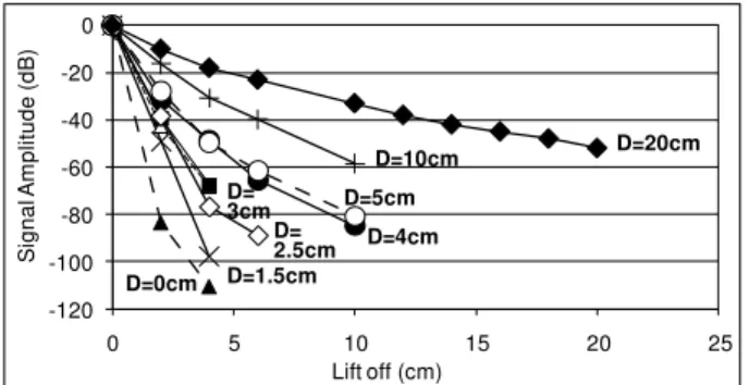
length). Figure 4 shows examples of received ultrasonic signals for d = 0cm (contact) and 20cm. It is evident that the IUT with d = 20cm could detect the received signal reflected from the bottom of the steel plate with sufficiently high signal to noise ratio. -0.5 -0.3 -0.1 0.1 0.3 0.5 0 5 10 15 20 25 Si g n a l Am p lit u d e (V) Time Delay (μs) -0.5 -0.3 -0.1 0.1 0.3 0.5 0 5 10 15 20 25 Si g n a l Am p lit u d e (V ) Time Delay (μs) (a) d = 0cm (b) d = 20cm Fig.4 Examples of received ultrasonic signals Figure 5 shows the relation between d and the amplitude of the received signal for various D of the coils. It was verified that induction coupling coefficient enhances as D increases. For example, it was -4.5dB for each additional d = 1cm in the case of D = 20cm and -40dB/cm in the case of D = 0cm.
-120 -100 -80 -60 -40 -20 0 0 5 10 15 20 25 Si g n a l Am p lit u d e (d B) Lift off (cm) D=20cm D=4cm D=5cm D=10cm D= 2.5cm D= 3cm D=0cm D=1.5cm
Fig.5 Liftoff characteristics
In addition, it is observed that the center frequency and bandwidth reduces when d increases as shown in Fig.6. This indicates that the Ze of the
sensing system changes with the change of d.
9.5 10 10.5 11 11.5 12 12.5 0 10 20 C e n te r fre q u e n c y (M H z) Liftoff (cm) 0 0.5 1 1.5 2 2.5 3 3.5 4 4.5 0 10 20 Ba n d W id th (MH z) Liftoff (cm) IUT IUT+Coil IUT IUT+Coil
(a) Center frequency (b) Bandwidth Fig.6 Spectral characteristics (D = 20cm) 5. Conclusions
The preliminary results of an induction-type noncontact method using two electrical coils for an IUT deposited onto a steel plate were presented. The ultrasonic signals transversing back and forth in the 12.7 mm thick steel plate were successfully detected in this experiment even if the liftoff distance exceeded 20cm. To improve the liftoff characteristic, it is effective to increase the internal diameter of the circular coil. However, it is necessary to adjust the electrical impedances of the coils connected to the pulser and IUT. This means that it is necessary to reduce the number of turns of the coil as its diameter increases. Such a noncontact technique may be highly desirable for fast NDE and NDE of rotating components.
References
1. M. Kobayashi et al.: Jpn. J. Apl. Phys. 46 (2007) 4688.
2. D. Greve et al.: IEEE Sensors J. 7 (2007) 295. 3. M. Kobayashi et al.: J. Intelligent Mat. Systems