Publisher’s version / Version de l'éditeur:
Advanced Engineering Materials, 10, September 9, pp. 775-787, 2008
READ THESE TERMS AND CONDITIONS CAREFULLY BEFORE USING THIS WEBSITE. https://nrc-publications.canada.ca/eng/copyright
Vous avez des questions? Nous pouvons vous aider. Pour communiquer directement avec un auteur, consultez la première page de la revue dans laquelle son article a été publié afin de trouver ses coordonnées. Si vous n’arrivez pas à les repérer, communiquez avec nous à [email protected].
Questions? Contact the NRC Publications Archive team at
[email protected]. If you wish to email the authors directly, please see the first page of the publication for their contact information.
Archives des publications du CNRC
This publication could be one of several versions: author’s original, accepted manuscript or the publisher’s version. / La version de cette publication peut être l’une des suivantes : la version prépublication de l’auteur, la version acceptée du manuscrit ou la version de l’éditeur.
For the publisher’s version, please access the DOI link below./ Pour consulter la version de l’éditeur, utilisez le lien DOI ci-dessous.
https://doi.org/10.1002/adem.200800241
Access and use of this website and the material on it are subject to the Terms and Conditions set forth at
Porous Metals and Metallic Foams: Current Status and Recent
Developments
Lefebvre, Louis-Philippe; Banhart, John; Dunand, David
https://publications-cnrc.canada.ca/fra/droits
L’accès à ce site Web et l’utilisation de son contenu sont assujettis aux conditions présentées dans le site LISEZ CES CONDITIONS ATTENTIVEMENT AVANT D’UTILISER CE SITE WEB.
NRC Publications Record / Notice d'Archives des publications de CNRC:
https://nrc-publications.canada.ca/eng/view/object/?id=c1ffff12-8cb6-4de6-9450-ce0986134333
https://publications-cnrc.canada.ca/fra/voir/objet/?id=c1ffff12-8cb6-4de6-9450-ce0986134333
Porous Metals and Metallic Foams:
Current Status and Recent
Developments**
By
Louis-Philippe Lefebvre,* John Banhart and David C. Dunand
1. Introduction
Cellular metals and metallic foams are metals with pores deliberately integrated in their structure. The terms cellular
metals or porous metals are general expressions referring to
metals having large volume of porosities, while the terms
foamed metal or metallic foams applies to porous metals
pro-duced with processes where foaming take place. Besides, the term metal sponge refers to highly porous materials with com-plex and interconnected porosity where the porosity cannot be subdivided into well defined cells.
Porous metals and metallic foams have combinations of properties that cannot be obtained with dense polymers, met-als and ceramics or polymer and ceramic foams. For example, the mechanical strength, stiffness and energy absorption of metallic foams are much higher than those of polymer foams. They are thermally and electrically conductive and they maintain their mechanical properties at much higher temper-atures than polymers. Besides, they are generally more stable in harsh environments than polymer foams. As opposed to ceramics, they have the ability to deform plastically and ab-sorb energy. If they have open porosity, they are permeable and can have very high specific surface areas, characteristics required for flow-through applications or when surface ex-change are involved.
–
[*] L.-P. LefebvreNational Research Council Canada Industrial Materials Institute
75 de Mortagne, Boucherville, Québec, J4B 6Y4, Canada E-mail: [email protected]
Prof. J. Banhart
Helmholtz Centre Berlin for Materials and Energy (Hahn-Meitner-Institute)
Glienicker Str. 100, 14109 Berlin, Germany Prof. D. C. Dunand
Northwestern University
Department of Materials Science and Engineering Evanston, IL 60208, USA
[**] The author would like to thank F. García-Moreno from HMI
Berlin, Y. H. Lee from the Chonnam National University, B. Sicotte from Biorthex, R. Goodall from the École Polytechnique de Lausanne, S. Reinhardt from Gleich, V. Paserin from Vale Inco, M. Chen from the Tohoku University and J. Rösler from the Technical University of Braunschweig for providing the pictures used in this review.
Porous metals and metallic foams are presently the focus of very active research and development
ac-tivities. There are currently around 150 institutions working on metallic foams worldwide, most of
them focussing on their manufacture and characterisation. Various companies are developing and
pro-ducing these materials which are now being used in numerous industrial applications such as
light-weight structures, biomedical implants, filters, electrodes, catalysts, and heat exchangers. This review
summarizes recent developments on these materials, with particular emphasis on research presented at
the latest International Conference on Porous Metals and Metallic Foams (MetFoam 2007).
REVIEWS
One of the first reference to man-made porous metals in the literature dates back to Pliny the Elder (77 AD) who reported a process called granulation used by Etruscan gold-smiths to produce fine jewellery pieces.[1]While some civili-zations developed innovative processes to produce porous metals, these techniques were, up to recently, mostly in-tended for surface treatments and mainly used for aesthetic purposes (jewellery, religious artefacts).
Indeed, porous metals only started to be used in engineer-ing applications at the beginnengineer-ing of the 20thcentury. Sintered powder and meshes were the first porous metals commer-cially available and used in engineering applications. Sintered powder has been used with success for the fabrication of fil-ters, batteries and self lubricated bearing since the 1920’s.[2,3] These materials are still in use today in high-volume applica-tions.
The first reference to metallic foams (corresponding to fab-rication processes where a material or material precursor is foamed to create an expanded structure with high porosity) is a French patent published in 1925.[4]The commercialisation of metallic foams started three decades later in the late 1950’s in the USA, where much research and development (R&D) was carried out for about ten years.[5]Little activity remained until a second surge of worldwide R&D activities started in the 1990’s which is still ongoing. With those recent develop-ments, these materials became commercially available in a wide variety of structures and properties.
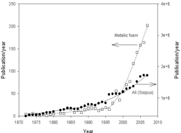
Figure 1 presents the evolution of the number of annual publications on metallic foams since the early 1970’s. Scientif-ic publScientif-ications on the subject were very scares until the early 1970’s. The number of publications then increased slowly and linearly to the mid 1990’s when the number of published arti-cles on the subject surged strongly, with a 20 % annual increase since 2000.
A series of international and national research and devel-opment programs has recently focussed on cellular metals: The US Multidisciplinary Research Initiative on Ultraligth Metals (MURI) launched in 1996, different European research projects funded within the 4th and 5th EU Framework pro-gram and a research propro-gram funded by the German Research Council in the late 1990’s.[6]
Since the late 1990’s, a biennial conference (Metfoam) reviews the latest progress in this area.[7,8,9,10,11] This paper presents the status of the cellular, porous or foamed metal technology and some recent developments in this field in the light of the latest, 5thMetFoam conference which took place in 2007 in Montréal (Canada). The paper is divided into three sections: materials development, characterization and appli-cations. The list of references concentrates on recent articles, with 115 of the 143 references given here published between 2006 and 2008.
2. Materials
The selection of the material structure is generally based on the end-application. Closed-cell materials provide good mechanical properties but do not allow access to their inter-nal surface. Therefore, they are mostly used in structural, load-bearing applications. In contrast, open porosity is gener-ally required for functions associated with the interior of the material. Accordingly, open-cell foams are mostly used in functional applications where load-bearing capability is not the primary goal. The present section is divided into these two groups of applications, while keeping in mind that dual or multiple uses are possible.
2.1. Materials for Structural Applications
2.1.1. Closed-Cell Metallic Foams
Closed-cell metallic foams can be manufactured in many different ways as described in various reviews.[6,12,13]In most cases, a metallic melt is stabilised with non-metallic particles, foamed by a gas and solidified. Gas bubbles are created by gas injection or by decomposing a chemical blowing agent in the melt. These bubbles do not merge or rupture due to the presence of stabilising particles.[14] The main R&D areas are presently centred on the investigation of foaming and stabili-sation mechanisms, the development of new blowing agents, the optimisation of the fabrication processes and the reduc-tion of the fabricareduc-tion costs.
Some research is directed towards understanding in more detail the complexities of foaming. Indeed, it is still not com-pletely understood how metallic films are formed within liq-uid metal foams and how foams are stabilised. Since foams are complex mixtures of solid, liquid and gaseous phases, their study is challenging, both experimentally and theoreti-cally. Single liquid metallic films have been used to help understanding the properties of the cell walls and better
Fig. 1. Evolution of the annual number of publications on porous metals and metallic foams. The numbers were obtained by searching publications with the concept porous metal or metallic foams in the key words field in Scopus (i.e. KEY((metal* W/1
foam*) OR (cellular PRE/1 metal*) OR (porous PRE/1 metal*))). The evolution of the total amount of publications listed in Scopus is presented for comparison.
REVIEWS
understand foaming and stabilisation.[15,16] X-ray imaging techniques have also been utilized to reveal the inner volume of expanding foam and to measure some structural parame-ters, such as the rupture time of individual films.[17] Observa-tion of metallic foams in other spectral ranges was also found to yield useful information. An optical technique has been used for the contactless imaging of expanding metal foams in 3D by placing the sample on a rotating plate inside a fur-nace.[18] The temperature distribution in expanding alumi-num foam was recorded in-situ using an array of micro-bol-ometers operating in the far infrared regime and was integrated in a commercial thermal camera.[19]
Foam stabilisation can be obtained by adding ceramic par-ticles into the metallic melt, which adhere to the gas/metal in-terfaces during foaming and prevent pore coalescence. One foam production process (sometimes referred to as the ‘Alcan process’) uses liquid metal matrix composites (MMCs) con-taining 10–20 vol.% particles (typically 10 lm silicon carbide or alumina particles) into which a blowing gas is injected. Very regular and highly porous metal foams can be produced with this method. However, the high particle content makes the solid foams very brittle and hard to machine. Replace-ment of the large particles in the MMCs by nanometric parti-cles is a solution to overcome this problem. Using nanoparti-cles, melts can be foamed at much lower particle loading. Indeed, 5 % of 70 nm SiC particles dispersed ultrasonically in the melt were shown to be sufficient to stabilised aluminum foams.[20]Particles formed in-situ by chemical reactions have also been used with success for the same purpose. As an ex-ample, 4 wt.% of TiC particles (200–1000 nm) formed in-situ in liquid aluminum resulted in stable aluminum alloy foams.[21]
Another area of investigation involves the development and improvement of the blowing agents. TiH2 has been in use since the 1950’s[22]and is presently considered the most powerful blowing agent available for the production of alu-minum and magnesium alloy foams. Efforts to replace or to improve this agent are important for two reasons. The first is the high cost of this hydride (∼ 80 u /kg, 2008 price). Since 0.5 to 1.5 wt.% TiH2 are needed to produce an aluminum foam, the blowing agent contributes significantly to the final cost of the material. Taking into account the price of Al melt (1.50 u/kg) or powder (3 u/kg), the blowing agent contrib-utes to up to 25 % of total raw material costs. Replacing TiH2 by a less expensive blowing agent, namely CaCO3, is being investigated by different researchers.[22,23,24,25] A second rea-son for the replacement of TiH2is associated with its decom-position behaviour that does not perfectly match the melting characteristics of most aluminum alloys used for foaming. In fact, TiH2 decomposition starts at temperatures lower than the melting temperature of aluminum or magnesium alloys. This negatively affects foaming by premature hydrogen release in the solid state and losses through the porosity net-work between the aluminum particles. Various strategies are currently under study to overcome this problem. One option
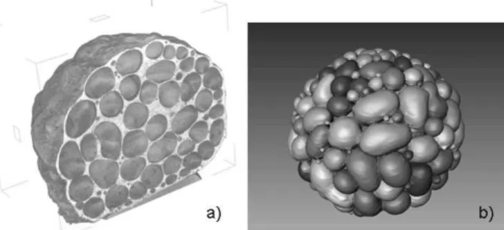
is to modify the TiH2powder in order to alter its decomposi-tion characteristics. This can be done by oxidadecomposi-tion[26,27]or by coating the particles with a thin layer of nickel.[28] Another option is to work without blowing agent (see Fig. 2) and rely on gas residues contained in powder or scrap that is added to the melt. In this case, pressure is used to control the foaming of the melt.[29,30,31]
Another cost reduction strategy is to use chip waste, e.g. from machining, as replacement for the expensive aluminum alloy powders. Chips are mixed with ceramic additives and TiH2and densified by compressive torsion processing[32] or thixocasting[33] after which the compacted materials are foamed in the usual manner. An open question remains, however, whether the need for more expensive compaction techniques contradicts the materials cost saving issue.
The fact that metal foam manufactured from powders in-cludes many processing steps has been one of the motivations of work focussing on integrating various steps into one. High pressure moulding of structural foams was proposed in that direction. The process consists of injecting an aluminum alloy melt into a die casting machine together with the blowing agent MgH2and allowing the controlled foaming of the com-ponents inside the die.[34]Structural foam components with a closed outer surface can be manufactured using this method.
Most of the recent R&D activities on closed-cell metallic foams have focussed on the development of aluminum based foams. This is principally because the melting point of alumi-num is low, the processing simple and alumialumi-num foams pro-vide favourable mass-specific mechanical properties. Efforts to develop foams with other metals are nevertheless ongoing, including steel, superplastic zinc,[35]magnesium[29]and even heavy elements such as gold.[36]
2.1.2. Iron Based Materials
Iron based foams have been considered as an alternative to aluminum foams, because steel has higher strength, higher capability to absorb energy and is generally cheaper than alu-minum. However, steel is denser than aluminum, and its much higher melting temperature makes low-cost production of foams a challenge. Various processes are presently in
Fig. 2. Al-Cu-Mg alloy foamed without blowing agent by pressure manipulation, i.e. melting a powder compact under 6 bar pressure (Argon) and releasing pressure to 1 bar; a) visualisation of foam by X-ray tomography, b) computer-assisted segmenta-tion of individual pores in the sample (Courtesy of F. García-Moreno, HMI Berlin).
REVIEWS
development to overcome these problems, most of them fol-lowing ideas which have been proposed previously.[12]A pro-cess was proposed to foam cold-pressed precursors made of pure (electrolytic) iron, graphite and hematite powders, between the solidus and liquidus temperatures. Foaming is driven by the CO and CO2generated by the reduction of the iron oxide by carbon.[37]Iron foams with porosity of approxi-mately 55 % were obtained using the process. An alternative method uses less expensive powder (i.e., water atomized powders) and a slip reaction sintering process to produce steel foams with compressive strength significantly higher than that of aluminum foams.[38] The material density (2.3–3.0 g/cm3) is, however, also higher than that of alumi-num foams. High strength stainless steel foams were also produced with powder metallurgy approaches[39,40]that may represent an interest when high mechanical strength and cor-rosion resistance are required. Besides, steel hollow spheres with high strength have been prepared and characterized.[41]
The densities of most iron based foams are still high and additional work is required to develop steel foams with lower density. Most work has been performed up to now in labora-tories on small specimens and developments are still needed to be able to produce large panels or structural parts with homogeneous and reproducible structures, with good prop-erties at reasonable costs.
2.1.3. Metal Foam-Based Composites
Combining metal foams with other materials offers unique opportunity to tailor material properties. The simplest ap-proach is to fill hollow sections with foam or to produce sand-wich structures with a metal foam core and a variety of face sheets, see Ref.[42] for a review. The potential for improve-ments is still large as demonstrated by the combination of aluminum foam and glass-fibre reinforced polymer compos-ites and aluminum alloy sheets[43]or by composites contain-ing aluminum foam spheres bonded together with a poly-meric adhesive.[44] A related approach is to deposit a high-strength coating on the struts of a foam, as demonstrated with nanocrystalline Ni-W coated aluminum foams showing improvements in strength and energy absorption.[45]
2.1.4. Amorphous Metallic Foams
As recently reviewed,[46,47] various liquid-state methods have been demonstrated to create Pd- or Zr-based bulk metal-lic glasses (BMG) foams. Porosity can be created by precipita-tion of dissolved hydrogen during cooling,[48]gas entrapment in the melt followed by expansion in the supercooled-liquid state,[49]infiltration of a bed of hollow spheres to create syn-tactic foams,[50,51]and infiltration of salt space-holder particles which are removed by dissolution in acidic solutions.[52,53] Solid-state methods have also been used: dissolution of crys-talline phase from an extruded amorphous-cryscrys-talline com-posite[54] and selective dissolution of one of the two amor-phous phases of an alloy.[55]Beside reducing density, pores in
amorphous metals improve significantly their compressive ductility, from near zero in the bulk to values as high as 80 % for cellular architectures. This is explained by shear-band in-terruption by individual pores at low porosities and stable plastic bending of thin struts at higher porosities.[56,57]
2.1.5. Metallic Hollow Spheres
Research and development on metallic hollow spheres are conducted in various research groups around the world. The process has been used to produce high-strength steel hollow spheres.[41] Composites and syntactic structures have also been developed with hollow spheres for structural applica-tions.[58,59]A process to produce hollow Cu2O and NiO nano-particles via the oxidation of Cu and Ni nanonano-particles has also been presented.[60]Modelling has been used to study the compression of hollow spheres. Maps showing the deforma-tion mechanisms that govern the plasticity of the spheres have been produced.[41,61]
2.1.6. Wire Mesh Structures
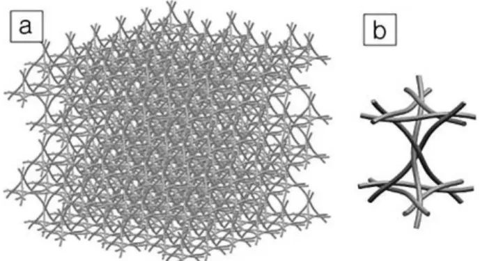
Recently, a technique to fabricate multi-layered Kagome truss periodic structures named ‘Wire-Woven Bulk Kagome (WBK) truss’ has been developed.[62,63,64,65]The fabrication is based on the assembly of helical wires in six directions. The structures are periodic and very uniform, have good specific properties and are highly permeable (Fig. 3). Different mate-rials have been produced with this process so far (iron, steel, aluminum) and the production methods and techniques have been studied for various applications. The properties of some of these structures were compared to other periodic cellular structures in Ref.[66] The compressive behaviour (apparent moduli and peak stress) of stainless steel structures of differ-ent sizes were studied and compared with analytically pre-dicted values by Lee et al.[67]The results show that the effec-tive modulus of the specimen is insensieffec-tive to the specimen size while the peak stress rapidly increases with a reduction of the specimen size. Similar cast aluminum lattice block structures (LBS) have been studied in the past,[68] and have recently been cast with Ti-6Al-4V titanium alloy.[69]
Fig. 3. a) Wire-woven Bulk Kagome (WBK) structure and b) unit cell (Courtesy of Y.H.Lee. Chonnam National University).
REVIEWS
2.2. Materials for Functional Applications
2.2.1. High Temperature Resistant Materials
There has been recently an interest for the development of cellular metals for high temperature filtration and solid-oxide fuel cells operating at elevated temperatures. The EURO IV regulations recently imposed stricter particulate emission limitations for passenger cars in Europe which will force automotive manufacturers to adopt new solutions and tech-nologies in the coming years to reach these objectives.[70] Fil-ters trap soot particles produced by the diesel engines and catalysts convert various toxic gases and lower the soot com-bustion temperature allowing the filter to regenerate.
As the efficiency of the engine is affected by the pressure drop at the exhaust, materials with good permeability are required. Metallic foams with good corrosion resistance at temperatures up to 600–800 °C, especially NiCrAl based alloys, are being considered for these applications. Different processes are being developed and new high- temperature resistant foams are now being produced.
Walther et al. presented a process to produce high temper-ature resistant Fe-Ni-Cr-Al foams using the deposition and transient liquid phase sintering of fine pre-alloyed particles onto thin commercially available nickel foam strip.[71]Filters are produced either by coiling the foam strip or by sintering the sheets in stacks. Long term stability, provided by a protec-tive layer consisting of a-alumina on the surface, was demon-strated at temperatures up to 950 °C. Compared to the state-of the-art wall-flow filters, the regeneration state-of the foam filters occurs faster and at lower temperatures because of the im-proved soot-filter wall contact provided by the turbulent gas flow. Choe et al. have proposed a similar approach to pro-duce heat-resistant foams using vapour deposition of Al and Cr (pack-aluminization and chromizing) on nickel foam strips followed by a homogenisation treatment to produce Ni-Cr and Ni-Cr-Al foams.[72] The foam yield strength was increased three-fold compared to pure Ni foam and the oxi-dation kinetics of Ni-Cr revealed similar behaviour to bulk Ni-Cr alloys, after taking into account the higher surface area of the foam. Angel et al. presented a process to produce In-conel 625 foams using slurries of particles.[73] They showed that the material maintains its compressive properties up to 600 °C and can withstand thermal shock up to 1000 °C. A strategy proposed to enhance the chemical stability of the material was to depose TiN on the surface using chemical vapour infiltration (CVI) processes. Casting replication of an oxide space-holder has also been demonstrated to create sponges from an oxidation resistant Ni-Mo-Cr alloy devel-oped for fuel cell interconnects.[74]
2.2.2. Materials with Elongated Pores
Important infrastructure and research activities have been set up recently at the Osaka University in Japan on the devel-opment of solidification techniques using a high-pressure gas
method (lotus materials or Gasar). These activities have sup-ported the development of these processes and production methods.[75,76]Various materials are now produced on a labo-ratory/pilot plant scale (Cu, Ni, Mg, Al, Si, TiAl, alumina). Recent work showed promising results on the use of chemical foaming agents to avoid using large volume of pressurized hydrogen, that represent potential hazard risks for the large scale manufacturing with the traditional high pressure gas methods.[77–79]
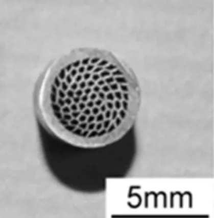
Koh et al. presented an alternative process to produce an-isotropic porous tubular structures by extruding copper and aluminum wires, followed by leaching of the aluminum to produce tubes with long elongated pores.[80] The resulting structures, shown in Figure 4, have low tortuosity and high permeability. A similar approach, using polymer or organic binders instead of aluminum followed by extrusion, has been demonstrated for various metals including copper, with applications for heat sinks and heat exchangers.[81]A related approach consists of sintering titanium powders around steel wires which are then removed electrochemically.[82]Titanium with aligned, elongated pores has also been produced by di-rectional freeze-casting of aqueous slurries.[83] Ice dendrites grow directionally in a temperature gradient, pushing Ti par-ticles into interdendritic spaces. After removal of the ice by freeze-drying, the powders are sintered, forming walls sepa-rating elongated pores which replicate the dendrites.
2.2.3. Biomaterials
Porous coatings have been initially proposed at the end of the 1960’s to overcome problems encountered with bone ce-ment. The goal was to produce a rough surface that increases the friction forces between the implant and the surrounding bone thus providing better initial stability to the implant. After implantation, the bone grows into the porous surface and helps to secure the long term stability of the implant. These coatings are now extensively used in various orthopae-dic applications. Research has recently switched from thin porous bead coatings, sintered mesh and thermal sprayed rough coatings to metallic foams (Fig. 5) and these materials
Fig. 4. Cross section of tubular structure obtained by extrusion and sacrificial leaching (Courtesy of H. Koh from the Osaka University).
REVIEWS
have been used in the development of various new and im-proved treatments (i.e. bone augmentation, graft free vertebra fusion for the treatment of degenerative disk diseases for example). Levine reviewed some uses of metallic foams in joint replacements in Ref.[84] while Schiefer et al. presented the development of porous titanium for the production of dental implants in.[85]
Research now focuses on the development of new process-es and materials to improve the performance of the materials (better initial stability, faster bone ingrowth) and reduced production cost. The materials being developed are mostly titanium alloys and Nitinol (tantalum being already used clinically). Heinl et al. presented a selective electron beam melting technique to produce periodic titanium structures with porosities ranging between 56 % and 86 %.[86]Directional freeze-casting has also been applied to produce titanium foams with 60 vol.% aligned pores.[87]The properties of Niti-nol porous materials produced by injection molding with a spacing agent were also reported.[88]The process allows pro-ducing components to net shape and the resulting material exhibits porosity up to 70 % and good mechanical properties.
The effects of the structure and composition on the proper-ties of porous metals for biomedical applications have been studied and documented by various researchers. The effect of oxygen and oxygen distribution on the properties of titanium foams has been documented.[89] Oxygen in solution affects the yield strength and the ductility of the foams. In contrast, oxygen coming from surface oxide has minimal effect on the compression behaviour under monotonic loading. Since the specific surface area of metallic foams can be high, the oxide layer may be a significant contributor to the total oxygen con-tent in the foam. Accordingly, it is important to discriminate the amount of the oxygen coming from the solution and sur-face oxide when controlling the amount of oxygen in the foams. The effect of various surface modification treatments (annealing, TiN, TiO2, and pre-treatments in simulated body fluids (SBF)) on nickel ion release from porous Nitinol was given.[90]The best results were obtained by combining a TiN coating with SBF pre-treatment. This treatment brings the nickel lifetime release for an average size spinal implant to one eighth of the quantity of nickel absorbed in a one day normal diet.[90]Li et al. presented the properties of titanium foams produced with different processes and having
differ-ent structures.[91]Their results indicated that cells grows (i.e. bone area and depth of bone ingrowth) was not necessarily linked to permeability but to material porosity and surface area. Since cells are growing on surfaces, larger surface area is believed to promote cell ingrowth. This should be valid as long as the connectivity between the cells allows the migra-tion of the cells from pores to pores.
2.2.4. Nanoporous Materials
Nanoporous metallic structures have recently attracted the interest of the scientific community. These materials, charac-terized by very high specific surface area and fine pore size, have been considered in electrodes, catalyst, sensors, actua-tors and filtration applications.[92,93,94]Most research is pres-ently done using leaching or de-alloying techniques. While dealloying techniques applied to gold, silver and copper alloys have been studied for many years by various research-ers, the mechanisms responsible for their formation remained not well understood until recently. A model of selective dis-solution where the atom clusters and forms islands rather than being uniformly distributed over the surface was pro-posed.[95]Monte Carlo simulations of the dissolution of silver and diffusion of silver and gold during Ag-Au dealloying allowed for reproducing the mechanisms of dealloying (mor-phology and kinetics).[96]
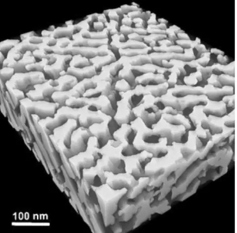
In addition to dealloying, other processes are being devel-oped to produce materials with submicron porosities, e.g. a selective dissolution technique to leach Ni-based superalloys that contain c’-precipitates in a c-matrix.[97] The resulting material (Fig. 6) has fine and regular submicron porosity, is permeable and is mechanically strong. The materials could be suited in membrane applications where fine porosity, thermal stability, mechanical strength and ductility are required. Amorphous metals with submicron porosity have also been achieved by selective leaching in amorphous/crystalline or amorphous/amorphous metal composites.[98,99]Finally, Utsu-nomiya et al. recently presented the formation of submicron pores on the surface of carbon steel using oxidation/reduc-tion treatments.[100]
Fig. 5. Porous titanium coating on an acetabular cup for hip replacement (Courtesy of National Research Council Canada, Industrial Materials Institute) and b) porous Niti-nol for cervical vertebra fusion (Courtesy of Biorthex).
Fig. 6. Microstructure of a c-membrane with submicron aligned porosity obtained after dissolution of the c′-phase in Ni-based superalloys [97].
REVIEWS
3. Characterisation, Modelling, and Methodology
3.1. StructureModelling the properties of porous materials highly relies on the characterization of the material structure. Because me-tallic foams and porous metals have complex architectures and microstructures, the measurement and parameterization of their structural characteristics still represent important challenges. Besides density and pore size, the properties of the material are strongly affected by many structural parame-ters such as the shape of the pores, the window and strut size, distribution, shape and density, the tortuosity, surface rough-ness, surface area, etc.
Application of X-ray tomography with laboratory X-ray tubes to characterize foam structures is now common prac-tice. Figure 2 shows an example of how a metal foam can be visualised in 3D with these techniques. Structures were stud-ied in a similar way using synchrotron X-rays to achieve bet-ter image quality.[61] Measuring density profiles[24,34] or cell shape anisotropies[18]by means of X-ray tomography is now becoming a routine investigation. The densification process of foams has also been analysed using deformation stages[101] and even in-situ.[102]Data acquisition and reconstruction lead-ing to the image is now a well-established procedure unless very high spatial resolutions (i.e. well below 1 lm) or good contrast between similarly absorbing phases is required.
New analytical tools, especially high resolution tomogra-phy, have been recently developed and optimised to help quantify the complex structure of metallic foams. Recent de-velopments include the work by Toda et al.[103]on the use of K-edge subtraction imaging on synchrotron X-ray microto-mography to map 3D Zn distribution in aluminum foams. Electron tomography was used to obtain 3D images on nano-porous materials with excellent resolution,[104]as shown in Figure 7.
The extraction of reliable structural parameters from porous materials still remains a challenge. Image analysis techniques have been used with success on 2D images.
Savard et al.[105]used automated image analysis to quantify pore diameter on open cells foams with simple structure using optical images. Image analysis techniques allow elimi-nating subjective selection criteria, speed up measurement procedures and help getting better statistical results. Contrast being less defined than on polished cross section, special care must be taken during sample selection and preparation, anal-ysis routine construction, implementation and validation. For 3D images, the complexity of the algorithm, the contrast level and the large size of the image to analyse remain
challeng-ing.[106]With standard equipment, the resolution may not be
sufficient to characterize some features of the material (sur-face area, pores in the strut wall, cracks, etc.).
Blouin et al.[107]developed laser-ultrasonics tools to moni-tor the bonding between porous and dense materials. The technique uses the monitoring of the vibration frequencies to determine the presence of unbound regions. The method has been used with success on porous and dense surfaces and could be used to monitor the bonding between a porous core and face sheets in sandwich panels or to determine the quality of bonding between porous coating and solid sur-faces.
3.2. Mechanical Properties
The study of mechanical properties of metallic foams re-mains an important topic, given that most foam applications are primarily load-bearing (e.g., for sandwich structures). Even foams whose main properties are functional (e.g., acoustic, thermal or surface area) require minimal mechanical properties to prevent damage or failure. Age-hardening of aluminum foams[108]was shown to improve strength of foams with large cell sizes (400 mm) but not with fine cell sizes (75 mm), an effect attributed to damage accumulation. Den-sity-graded aluminum foams were found to exhibit a smoothly rising plateau stress, unlike uniform foam with a near constant plateau stress. This behaviour was modelled with a simple series model based on semi-empirical scaling relationships for the compressive behaviour of uniform foams.[109]In-situ X-ray tomography has been used recently
by various groups, allowing for correlation with mechanical properties and deformation mechanisms. This method could elucidate deformation mechanisms of aluminum foams un-der monotonic or cyclic loading with lateral constraint.[110]It was also applied to hollow-sphere foams, so as to determine the main deformation mechanisms and compare with results of finite element modelling (FEM) calculations.[61,111]The me-chanical properties of such hollow sphere foams[112]and other adhesively bonded hollow spheres were further modelled by the FEM method alone.[113]FEM was also applied to investi-gate the effects of open-cell metallic foam irregularity on de-formation behaviour and energy absorption during impact loading.[114]Multi-scale modelling has been used to study the effect of precipitates, heat treatment and relative density on
Fig. 7. Transmission electron microscope (TEM) tomographic reconstruction of nano-porous gold (Courtesy of M. Chen, Materials Research Tohoku University).
REVIEWS
damage evolution and fracture in two-dimensional Voronoi structures.[115]Another advanced imaging technique – digital image correlation – was utilized for foams cycled under ten-sion/compression loading or uniaxial tensile loading, to cap-ture localized deformation (crush or tensile bands), cell wall fracture and global foam failure.[116,117]
3.3. Acoustic Properties
Metallic foams have been considered in various acoustic applications. On one hand, the unique structure of these ma-terials can provide good sound absorption characteristics.[118] On the other hand, their acoustic properties can be combined with other characteristics of the metallic foams (i.e. thermal and chemical stability, mechanical properties) to make them more attractive than common sound absorbers such as miner-al wool or polymer foams. Budget associated with sound management being generally low, metallic foams will find applications when substantial improvements are observed or when the combination of the properties of the metallic foams represents an important benefit (i.e. standard sound absorbers are generally much cheaper than most metallic foams).
Tang et al. recently presented the effect of layered struc-tures on the acoustic absorption of fibrous strucstruc-tures and showed that better sound absorption was obtained by apply-ing materials with the area of higher porosity facapply-ing the sound wave.[119]Modelling the acoustic properties of metallic foams is presently an area of development. Perrot et al. were able to model acoustic absorption in open-cell aluminum foams using reconstructed tetrakaidecahedron unit cells.[120] The unit cells with ligaments of triangular cross-sections were produced using measurements on X-ray microtomography images. The agreement with experiments was good in the medium-high frequency range. Other experiments are, how-ever, required to optimize the model in the low frequency range and to validate the model for foams having more com-plex structures.
3.4. Thermal Properties
Metallic foams are conductive, permeable and have high surface area. This combination of properties makes them at-tractive for various thermal applications (heat exchangers, heat sink, heat pipes). Various research centres are presently working on the characterisation[121–127]and modelling[128,129]of heat transfer and thermal exchanges in metal foams with var-ious structures.
Heat exchanges and conduction in metallic foams are com-plex phenomena. Heat exchange efficiency is affected by the conductivity of the foam, the heat exchange between the foam and the surrounding fluid and the pressure drop in the foam.
These characteristics are all affected by various structural parameters (density, pore size distribution, cell connectivity, tortuosity, strut size, density and geometry, surface rough-ness, etc.) that are difficult to measure and integrate. Accord-ingly, the thermal properties and efficiency of metallic foams are still not very well characterized. Hopefully, the on-going research will provide new data and tools for engineers and designers that will help better assess the performance of these materials in thermal applications.
3.5. Permeability
Permeability is an important property for flow-through foam applications such as thermal applications, filtration, electrochemistry, acoustic absorption, porous implants. Re-cent investigations showed that classical models such as Darcy’s or Forchheimer’s models do not describe appropri-ately the pressure drop in porous solid, especially at high fluid velocity. It was shown that the pressure drop cannot be normalised by the material thickness since entrance and exit effects can significantly affect the pressure drop.[130] Accord-ingly, new models should be developed and the methods to measure permeability should be re-evaluated, especially when the material thickness is small and the fluid velocity high. Bonnet et al. analyzed biphasic (air-water) flow in me-tallic foams and studied the effect of pore size and flow rate on pressure drop.[131]Models were compared to experimental results and reasonable agreements were obtained. Zhang et al. presented the effect of surface modification and wettability on the permeability of Fe-Cr-Al fiber mats.[132]The results in-dicated that the material’s wettability affects significantly the permeability of the materials. This demonstrated that control-ling the interaction forces between the porous media and working fluid may be used to control pressure drop in porous media. The effect of a perforation on the pressure drop and gas diffusion in metallic foams has been studied.[133] The work suggested that gas diffuses from the perforation into the foam and perforations can be used to reduce pressure drop while giving access to the internal surface of the foam. More work needs to be done to better understand gas diffu-sion in complex systems and to optimize the performance of flow through devices such as heat exchangers, electrodes or catalysts.
3.6. Standardisation
Besides characterising the properties of cellular metals in detail, a very important issue is the standardisation of mea-surement procedures. End-users of cellular metals will only rely on properties measured in a standardised way. For this reason, initiatives have been started to define such standards both in Europe and Japan.[134,135]
REVIEWS
4. Applications and Commercialisation
Porous metals and metallic foams have been commercially used for many years and various companies are producing these materials for different applications. Important commer-cial developments took place in the last 15 years on closed cell aluminum foams and sandwich panels for structural applica-tions and various companies are now commercializing these materials. The most important commercial applications of porous metals and metallic foams remain open-cell materials for the production of filters, gas-flow controlling devices, bat-teries, biomedical implants and bearings. This section pre-sents some recent developments on applications and com-mercialisation of cellular metals.
4.1. Aluminum Foams
Aluminum foam is currently produced by a number of companies worldwide. It is, however, sometimes difficult to assess how sustainable a commercial activity is because pre-cise information about production volumes and markets are not available. The activities of four companies are described below. Beside those, there are other companies in Canada, Austria, Korea and China that are producing aluminum foams.
Shinko Wire in Japan is the aluminum foam manufacturer with the longest track record, having started production in the 1990’s. Gleich (Germany) is the European distributor of Alporas foams produced by Shinko.[136]Gleich develops parts in co-operation with end-users and presented some new applications in the past years.[137]One part, presented in Fig-ure 8, is a vacuum elevator tool manufactFig-ured for Pilkington, a large manufacturer of flat glass products. The tool is used to lift glass panels produced in the floating glass process. The replacement of the full aluminum part by Alporas foam led to a weight reduction from 82 to 32 kg. Since the change of these tools is carried out manually, this reduced weight facili-tates handling. The production is still small scale (i.e., 5–6 pieces per year) but demonstrates the benefit of using aluminum foam for light-weight structural components. In this case, the heat resistance of aluminum foams plays an im-portant role since tool temperatures can be as high as 400 °C. The excellent machinability of Alporas foam further promotes the use of this material for this type of application.
Alulight (Austria) is now producing a crash element for an
Audi car with 100,000 parts per year. This is currently the only large-scale application of closed cell aluminum foams. This production required the development of an automatised production technology.[138] Applied Light-Weight Materials
(‘alm’) in Saarbrücken (Germany) is the leader on the field of
in-situ bonded, i.e. metallically bonded, aluminum foam
sandwich products. Their technology and some applications are described in detail in this issue of AEM. ‘alm’ recently merged with Alulight and the companies are now jointly developing the market. Applications are still small-scale (e.g. lifting arm for elevating platform, Alimex plates) but various new products are now in the prototyping stage (rocket cone, bicycle crank arm, cookware).[42]
Alcoa (USA) is a new player in the aluminum foam market.
In 2006, they presented a new process based on the continu-ous casting of the foam using CaCO3 as blowing agent.[24] One of the objectives is to reduce the cost of aluminum foams and use them in cost-driven products. Price estimation at 5 US$/kg is considered realistic after the technology has reached large-scale production.
Another closed cell aluminum foam part in production is the girder shown in Figure 9. It contains two Alporas foam cores encased in a cast aluminum alloy produced by low pressure die casting. The part is used in cutting and milling machines and serves as a load-bearing structure with a good vibration damping capacity in the frequency regime around 370 Hz. Vibrations level can be reduced by 60 % compared to the conventional part without foam. Since 2004, 2,500 pieces weighing 21 kg each have been manufactured by the com-pany Gleich.
Due to their good deformability and high energy absorp-tion capability, aluminum foams have been considered for the production of crash energy absorbers for many years. A crash bumper has been in use in light city railways for some years.[139] Other applications are being investigated such as an Alporas metal foam crash element in the front tip of the
Fig. 8. Vacuum lifting tool for Pilkington containing an Alporas aluminum foam ring (Courtesy of Sönke Reinhardt).
Fig. 9. Girder with Alporas foam core. The entire part length is 1900 mm; the foam core length is 1580 mm (Courtesy of Sönke Reinhardt).
REVIEWS
chassis of a racing car (Fig. 10). This element was shown to fulfil the requirements of a limitation of de-acceleration to < 20 g at 7 m/s impact velocity for a vehicle weight of 300 kg. Costs still prevent, however, the use of aluminum foams for those applications in mass markets.
Aluminum foam sandwiches (AFS) manufactured by ad-hesive bonding of flat Alporas panels and aluminum sheets (0.7 to 5 6mm thick) are produced for various applications in mechanical engineering and transport industry. Bonding adds about 1 kg to the weight of 1 6m2panels and represents about 10-30 % of the final product costs.
4.2. Open-Cell Materials
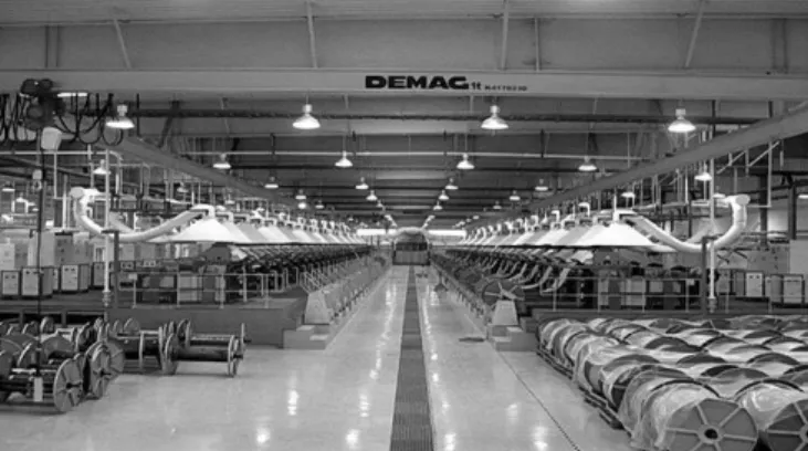
Electrodes for NiMH and NiCd batteries are probably the largest industrial applications of metallic foams nowa-days. Vale Inco produces annually about 4 millions square meters (4 square kilometres) of nickel foams for these applica-tions.[71] With the current development of other types of batteries (lithium ion batteries for example), demand will eventually be reduced. But, as these Ni foams are currently produced in large volume with uniform and controllable structure and properties at acceptable cost, they will surely find other large scale applications in the coming years. Fig-ure 11 shows a production plant located in China.
Another important commercial application of metallic foams and porous metals are the production of biomedical implants. Porous coatings (sintered beads and meshes) have been used with success for the last 20 years in orthopaedic
applications and most orthopaedic implant manufacturers are using these coatings on many of their implants. The com-panies are now developing metallic foams to improve the performance of their implants and to develop implants for new and improved surgical treatments. Major orthopaedic implant manufacturers are now bringing these materials into the market (Hedrocell from Zimmer, Tritanium from Stryker, Regenerex from Biomet, Gription from DePuy).
Important commercial developments also took place in the automotive industry. Nett Technologies Inc. is presently using open-cell metallic foams for the production of their cat-alytic converters for diesel engines.[140] Vale Inco Ltd and Süd-Chemie AG have recently agreed to establish a joint ven-ture, Alantum, for the production and marketing of catalyzed diesel emission control materials. The company will concen-trate initially on diesel oxidation catalysts (DOC) and diesel particulate filters (DPF) applications for European passenger car and light truck markets. The pilot plan is set to produce 100,000 m2of foams annually and the commercial scale pro-duction is expected to begin in 2008.[141]
Dynapore® porous 304L/316L stainless steel laminates (from MKI Corp) have found successful applications for the thermal management, flow distribution, membrane support and current collection components of fuel cell stacks.[142]Fuel cell still being in the early commercialization stage, they are not yet used in large volume. With the expected large scale commercialization of fuel cells, this may, however, become a large scale application of metallic foams.
Degussa AG recently developed low-density hollow spheres Raney-type catalysts. The hollow spheres produced with activated nickel or cobalt metals have high surface area. The material offers an increase in volumetric activity at lower catalyst bulk density without the presence of expensive, but not utilized, materials.[143]
New companies are still emerging and offering novel materials with different structures for different applications. Metafoam (Canada) for example, is a new company commer-cializing highly porous foams with open structures and high specific surface areas. The company focuses on the develop-ment of high efficiency heat exchangers for thermal manage-ments (copper) and electrodes (nickel). Using metallic foams, the company states that they significantly improved both the critical heat flux and surface superheat in two phase liquid cooling systems. This should help manage increasing heat flux in electronic devices cooling.
5. Summary
The technology of porous, foamed or spongy metals is still evolving at a fast pace. This research area is highly interdisci-plinary and requires chemistry, physics and materials engi-neering to be applied jointly to achieve integrated solutions that ensure that these materials can be produced economic-ally with the required quality and reproducibility and that their integration into engineering systems makes full use of
Fig. 10. Crash protector in a model racing car built by students at the University of Technology of Stralsund, Germany; a) view of car with the front encasement taken off, b) full view (Courtesy of Sönke Reinhardt).
Fig. 11. Nickel foam production unit at the Inco Advanced Technology Materials, Da-lian, China (Courtesy of V. Paserin).
REVIEWS
their unique property spectrum. It is anticipated that the fast development of the past years will continue.
–
[1] Pliny the Elder, Nat. Historiae, circa 77AD, Book XXXIV, 20.
[2] J. M. Capus, Met. Powders: A Global Survey of Production,
Appl. and Markets, Metal Powder Industries Federation
(MPIF), 3rdedition, 2000.
[3] A. O. Nilsson, Substitution of Rechargeable NiCd Batteries:
A background Document to Evaluate the Possibilities of Finding Alternatives to NiCd Batteries’,
http://www.re-chargebatteries.org/07_NilssonSubstitution.pdf. [4] M. A. Meller, Produit Métall. pour l’obtention d’objets
La-minés, Moulés ou Autres, et Proc. Pour sa Fabrication, 1925,
French Patent 615.147.
[5] J. Banhart, D. Weaire, Phys. Today 2002, 55, 37.
[6] H. P. Degischer, B. Kriszt, Handbook of Cellul. Met. 2002, Wiley-VCH, Weinheim.
[7] J. Banhart, M. F. Ashby, N. A. Fleck, Met. Foams and
Por-ous Met. Struct. 1999, MIT-Verlag Bremen and Special
Issue of Adv. Eng. Mat. 2000, 2 (4).
[8] J. Banhart, M. F. Ashby, N. A. Fleck, Cellul. Met. and
Met. Foaming Technol. 2001, MIT-Verlag Bremen and
Special Issue of Adv. Eng. Mater. 2002, 4 (10).
[9] J. Banhart, N. A. Fleck, A. Mortensen, Cellul. Met. –
Manufact. Properties, Appl. 2003, MIT-Verlag Berlin and
Special Issue of Adv. Eng. Mater. 2004, 6 (6).
[10] H. Nakajima, N. Kanetake, Porous Met. and Met. Foaming
Technol. 2006, The Japan Institute of Metals, Sendai and
Special Issue of Adv. Eng. Mater. 2006, 8 (9).
[11] L. P. Lefebvre, J. Banhart, D. C. Dunand, Porous Met.
and Metall. Foams, 2008, DEStech Pub., Pennsylvania.
[12] H. P. Degischer, B. Kriszt, Handbook of Cellul. Met. 2002, Wiley-VCH, Weinheim.
[13] J. Banhart, Prog. Mater. Sci. 2001, 46, 559. [14] J. Banhart, Adv. Eng. Mater. 2006, 8, 781.
[15] K. Kadoi, N. Babcsán, H. Nakae, F. García-Moreno, J. Banhart, 2008, in Ref. 11, 111.
[16] G. S. Vinod Kumar, F. García-Moreno, N. Babcsán, A. H. Brothers, B. S. Murty, J. Banhart, Phys. Chem.
Chem. Phys. 2007, 48, 6415.
[17] F. García-Moreno, A. Rack. L. Helfen, T. Baumbach, S. Zabler, N. Babcsán, J. Banhart, T. Martin, C. Ponchut, M. Di Michiel, Appl. Phys. Lett. 2008, 92, 134104.
[18] M. A. Rodriguez-Perez, E. Solórzano, J. A. De Saja, F. García-Moreno, 2008, in Ref. 11, 75.
[19] E. Solórzano, M. A. Rodriguez-Perez, F. García-Moreno, N. Babcsán, J. Banhart, 2008, in Ref. 11, 79.
[20] A. H. Brothers, J. Banhart, Verfahren zur Herstellung eines
Metallmatrix-Nanoverbundwerkstoffes, Metallmatrix-Nano-verbundwerkstoff und seine Anwendung. 2007, German
Patent Application DE 10 2007 044 565.4.
[21] N. Babcsán, B. S. Murty, G. S. Vinod Kumar, F. García Moreno, J. Banhart, 2008, in Ref. 11, 27.
[22] J. C. Elliott, Meth. of Producing Met. foam, 1956, US Patent 2751289.
[23] V. Gergely, D. C. Curran, T. W. Clyne, Comp. Sci.
Tech-nol. 2003, 62, 2301.
[24] J. D. Bryant, M. Crowley, W. Wang, D. Wilmhelmy, J. Kallivayalil, 2008, in Ref. 11, 19 and this issue of Adv.
Eng. Mater.
[25] S. Gnyloskurenko, A. V. Byakova, A. I. Sirko, A. O. Dudnyk, Y. V. Milman, 2008, in Ref. 11, 399.
[26] D. Lehmhus, M. Wichmann, M. Busse, 2008, in Ref. 11, 51.
[27] B. Matijasevic, J. Banhart, S. Fiechter, O. Görke, N. Wan-derka, Acta. Mater. 2006, 54, 1887.
[28] P. M. Proa-Flores, R. A. L. Drew, 2008, in Ref. 11, p. 55 and this issue of Adv. Eng. Mater.
[29] K. Renger, H. Kaufmann, Adv. Eng. Mater. 2005, 7, 117. [30] F. García-Moreno, J. Banhart, Coll. Surf. A 2007, 309, 264. [31] C. Jiménez, F. García-Moreno, J. Banhart, G. Zehl, 2008,
in Ref. 11, 59.
[32] N. Kanetake, M. Kobashi, S. Tsuda, 2008, in Ref. 11, 63 and this issue of Adv. Eng. Mater.
[33] J. Baumeister, J. Weise, A. Jeswein, M. Busse, M. Hae-sche, 2008, in Ref. 11, 83.
[34] H. Wiehler, P. Heinl, C. Körner, R. F. Singer, 2008, in Ref. 11, 15.
[35] K. Kitazono, T. Seo, Y. Takiguchi, 2008, in Ref. 11, 367. [36] J. Banhart, Gold Bull. 2008, in press.
[37] T. Murakami, K. Ohara, T. Narushima, C. Ouchi, 2008, in Ref. 11, 145.
[38] A. Fathy, A. Ahmed, H. Morgan, 2008, in Ref. 11, 161. [39] M. Gauthier, 2008, in Ref. 11, 149.
[40] M. S. Aly, H. Okuda, S. Ochiai, Y. Fukasawa, K. Mor-ishita, K. Kato, K. Kita, K. Honma, 2008, in Ref. 11, 157. [41] U. Jehring, P. Quadbeck, H.-D. Böhm, G. Stephani,
2008, in Ref. 11, 165.
[42] J. Banhart, H.-W. Seeliger, 2008, in Ref. 11, p. 3 and this issue of Adv. Eng. Mater.
[43] A. Talakola, G. Reyes, 2008, in Ref. 11, 379.
[44] K. Stöbener, J. Baumeister, G. Rausch, M. Busse, 2008, in Ref. 11, 383.
[45] Y. Boonyongmaneerat, C. A. Schuh, D. C. Dunand, Scr.
Mater. 2008, 59, 336.
[46] A. H. Brothers, D. C. Dunand, Scr. Mater. 2006, 54, 513. [47] A. H. Brothers, D. C. Dunand MRS Bull. 2007, 32, 639. [48] T. Wada, A. Inoue, Mater. Trans. 2004, 45, 2761.
[49] T. Wada, A. Inoue, Mater. Sci. and Eng. A 2007, 447, 254. [50] A. H. Brothers, D. C. Dunand, Appl. Phys. Lett. 2004, 84,
1108.
[51] A. H. Brothers, Q. Zheng, J. Xu, D. C. Dunand, J. Appl.
Phys. 2007, 102, 023508.
[52] A. H. Brothers, D. C. Dunand, Acta Mater. 2005, 53, 4427.
REVIEWS
[53] T. Wada, F. X. Qin, X. M. Wang, A. Inoue, M. Yoshi-mura, Mater. Trans. 2007, 48, 9.
[54] M. H. Lee, D. J. Sordelet, Scr. Mater. 2006, 55, 947. [55] J. Jayaraj, B. J. Park, D. H. Kim, W. T. Kim, E. Fleury,
Scr. Mater. 2006, 55, 1063.
[56] T. Wada, A. Inoue, A. L. Greer, Appl. Phys. Lett. 2005,
86, 251907.
[57] A. H. Brothers, D. C. Dunand, Acta Mater. 2005, 53 (16), 4427.
[58] A. Rabiei, L.Vendra, 2008, in Ref. 11, 387.
[59] J. Baumeister. J. Weise, K. Stöbener, M. Busse, 2008, in Ref. 11, 11.
[60] R. Nakamura, D. Tokozakura, J.-G. Lee, H. Mori, H. Na-kajima, 2008, in Ref. 11, 329.
[61] P. Lhuissier, M. Fivel, L. Salvo, Y. Brechet, 2008, in Ref. 11, 395 and this issue of Adv. Eng. Mater.
[62] K. J. Kang, G. P. Jeon, S. J. Nah, B. S Ju, N. H. Hong,
J. Korean Soc. Mech. Eng. 2004, A28, 296.
[63] Y. H. Lee, B. K. Lee, I. Jeon, K. J. Kang, Acta Mater., 2008, accepted.
[64] K. J. Kang, Y. H. Lee, 2005, US Patent Application 10/ 578, 421.
[65] Y. H. Lee, J. E. Choi, K. J. Kang, 2006, ASME Interna-tional Mechanical Engineering Congress and Exposition (IMECE2006), Chicago, USA, 15467.
[66] B.-K. Lee, M. H. Lee, K. J. Kang, 2008, in Ref. 11, 245, and this issue of Adv. Eng. Mater.
[67] B.-K. Lee, I. Jeon, K.-J. Kang, 2008, in Ref. 11, 177. [68] G. W. Kooistra, D. T. Queheillalt, H. N. G. Wadley,
Ma-ter. Sci. and Eng. A 2008, 472, 242.
[69] O. Li, E. Y. Chen, D. R. Bice, D. C. Dunand, Metall. and
Mater. Trans. A 2008, 39, 441.
[70] D. Fino, G. Saracco, in Cellul. Ceram.: Struct. Manufact.
Properties and Appl. Wiley-VCH, Weinheim 2005, 419.
[71] G. Walther, B. Klöden, T. Weissgärber, B. Kieback, A. Böhm, D. Naumann, S. Saberi, L. Timberg, 2008, in Ref. 11, 125, and this issue of Adv. Eng. Mater.
[72] H. Choe, D. C. Dunand, 2008, in Ref. 11, 141.
[73] S. Angel, W. Bleck, D. E. Hajas, Y. Jiang, J. M. Schnei-der, 2008, in Ref. 11, 129 and this issue of Adv. Eng.
Ma-ter.
[74] Y. Boonyongmaneerat, D. C. Dunand, Adv. Eng. Mat. 2008, 10, 379.
[75] M. Kashihara, H. Yonetani, S. Suzuki, S. K. Hyun, S. Y. Kim, Y. Kawamura, H. Nakajima, 2008, in Ref. 11, 201. [76] S. Suzuki, H. Nakajima, H. Utsunomiya, 2008, in Ref. 11,
205.
[77] H. Nakajima, 2008, in Ref. 11, 193.
[78] S.-Y. Kim, H. Nakajima, B.-Y. Hur, 2008, in Ref. 11, 197. [79] M. Tane, H. Nakajima, 2008, in Ref. 11, 241.
[80] H. Koh, H. Utsunomiya, J. Miyamoto, T. Sakai, 2008, in Ref. 11, 133 and this issue of Adv. Eng. Mater.
[81] L. Tuchinskiy, Adv. Eng. Mater. 2008, 10, 219.
[82] J. Kwok, D. C. Dunand, 2008, in this issue of Adv. Eng.
Mater.
[83] Y. Chino, D. C. Dunand Acta Mater. 2008, 56, 105. [84] B. Levine, 2008, in Ref. 11, p. 251 and this issue of Adv.
Eng. Mater.
[85] H. Schiefer, M. Bram, H.-P. Buchkremer, D. Stöver, 2008, in Ref. 11, 259.
[86] P. Heinl, C. Körner, R. F. Singer, 2008, in Ref. 11, 275 and this issue of Adv. Eng. Mater.
[87] Y. Chino, D. C. Dunand, 2008, in Ref. 11, 263.
[88] M. Köhl, M. Bram, H.-P. Buchkremer, D. Stöver, T. Ha-bijan, M. Köller, 2008, in Ref. 11, 295.
[89] L. P. Lefebvre, E. Baril, 2008, in Ref. 11, 255 and this issue of Adv. Eng. Mater.
[90] V. Lemaire, B. Sicotte, S. Allard, 2008, in Ref. 11, 291. [91] J. Li, C. Wilson, J. De Wijn, K. De Groot, C. A. Van
Blit-terswijk, 2008, in Ref. 11, 267.
[92] Z. Liu, P. C. Searson, J. Phys. Chem. 2006, 110, 4318. [93] H. Tanimoto, K. Yamoamoto, H. Mizubayash, 2008, in
Ref. 11, 318.
[94] J. Weissmüller, R. N. Viswanath, D. Kramer, P. Zimmer, R. Würschum, H. Gleiter, Sci. 2003, 300, 312.
[95] J. Erlebacher, M. J. Aziz, A. Karma, N. Dimitrov, K. Sieradzki, Nature 2001, 410, 450.
[96] Y. Ding, Y. J. Kim, J. Erlebacher, Adv. Mater. 2004, 16, 1897.
[97] J. Rösler, O. Nâth, S. Jâger, F. Schmitz, 2008, in Ref. 11, 321.
[98] M. H. Lee, D. J. Sordelet, Scr. Mater. 2006, 55, 947. [99] J. Jayaraj, B. J. Park, D. H. Kim, W. T. Kim, E. Fleury,
Scr. Mater. 2006, 55, 1063.
[100] H. Utsunomiya, S. Kawajiri, N. Takahira, T. Sakai, T. Tanaka, 2008, in Ref. 11, 153.
[101] H.-P. Degischer, A. Kottar, B. Foroughi, E. Maire, N. Godin, V. Carmona, S. Deschanel, F. Simancik, 2008, in Ref. 11, 39.
[102] M. Kolluri, M. Mukherjee, F. García-Moreno, J. Banhart, U. Ramamurty, Acta Mater. 2008, 56, 1114.
[103] H. Toda, Y. Takami, M. Kobayashi, T. Kobayashi, Y. Ar-uga, T. Takagi, 2008, in Ref. 11, 445.
[104] T. Fujita, L. Qian, K. Inoke, M. Chen, in the Proc. of the
16th Int. Microsc. Congress, Sapporo, Japan, 3–8 Sept.,
2006, 1864.
[105] M. Savard, 2008, in Ref. 11, 449.
[106] J. Banhart, Adv. Tomogr. Meth. in Mater. Res. and Eng. 2008, Oxford University Press, Oxford.
[107] A. Blouin, C. Neron, L. P. Lefebvre, 2008, in Ref. 11, 441. [108] Y. Conde, A. Mortensen, 2008, in Ref. 11, 335.
[109] A. H. Brothers, D. C. Dunand, Mater. Sci. Eng. A 2008,
489, 439.
[110] M. Mukherjee, F. García-Moreno, J. Banhart, M. Kolluri, U. Ramamurty, 2008, in Ref. 11, 347.
[111] A. Fallet, L. Salvo and Y. Brechet, 2008, in Ref. 11, 343, and this issue of Adv. Eng. Mater.
[112] T. Daxner, R. W. Tomas, R. D. Bitsche, 2008, in Ref. 11, 169.
REVIEWS
[113] K. Stöbener, J. Baumeister, G. Rausch, M. Busse, 2008, in Ref. 11, 383, and this issue of Adv. Eng. Mater.
[114] M. Borovinšek, Z. Ren, 2008, in Ref. 11, 371.
[115] K. R. Mangipudi, E. Amsterdam, J. Th. M. De Hosson, P. R. Onck, 2008, in Ref. 11, 363.
[116] M. D. Ingraham, C. J. Demaria, K. A. Issen, D. J. Morri-son, 2008, in Ref. 11, 351.
[117] K. A. Issen, C. J. Smith, M. L. Black, D. J. Morrison, 2008, in Ref. 11, 355.
[118] D. Pilon, R. Panneton, F. Sgard, L. P. Lefebvre, Canadian
Acoustics 2004, 32, 24.
[119] H. P. Tang, J. L. Zhu, J. Y. Wang, Y. Ge, C. Li, 2008, in Ref. 11, 181.
[120] C. Perrot, F. Chevillotte, R. Panneton, X. Olny, 2008, in Ref. 11, 433.
[121] O. Reutter, J. Sauerhering, T. Fend, R. Pitz-Pall, S. An-gel, 2008, in Ref. 11, 485, and this issue of Adv. Eng.
Mater.
[122] A. Berg, J. Baumeister, G. Rausch, M. Busse, L. Schna-bel, J. Bauer, 2008, in Ref. 11, 489.
[123] J.-H. Joo, K. J. Kang, B. S. Kang, 2008, in Ref. 11, 493. [124] D. Pilon, S. Labbé, R. Panneton, L. Fréchette, E. Gros,
J. F. Touzin, B. Marsan, 2008, in Ref. 11, 497.
[125] O. Andersen, T. Studnitzky, C. Kostamann, G. Stephani, 2008, in Ref. 11, 505.
[126] R. Suzuki, K. Kitazono, 2008, in Ref. 11, 493.
[127] H. Chiba, H. Nakajima, T. Tomimura, T. Ogushi, K. To-rii, F. Ono, 2008, in Ref. 11, 517.
[128] E. Brun, J. Vicente, F. Topin, R. Occelli, 2008, in Ref. 11, 509.
[129] E. Solórzano, J. Escudero, J. Lázaro, M. A. Rodriguez-Perez, J. A. De Saja, 2008, in Ref. 11, 501.
[130] A. Mostafid, M. Medraj, E. Baril, L. P. Lefebvre, 2008, in Ref. 11, 483, and this issue of Adv. Eng. Mater.
[131] J.-P. Bonnet, F. Topin, L. Tadrist, 2008, in Ref. 11, 467. [132] W. Zhang, Y. Li, Z. Xi, G. Li, A. Fu, J. Zhang, 2008, in
Ref. 11, 479.
[133] V. P. Rodrigues, M. D. M. Innocentini, L.-P. Lefebvre, E. Baril, 2008, in Ref. 11, 463.
[134] U. Krupp, J. Aegerter, A. Ohrndorf, A. Danninger, T. Hipke, J. Hohlfeld, M. Reinfried, 2008, in Ref. 11, 407. [135] Project report in New Energy and Industrial
Technol-ogy Development Organization (NEDO), Japan,
“Stan-dardisation of Testing Meth. of Porous Met” (in Japanese),
2006& 2007.
[135] http://www.gleich.de and http://www.shinko-wire. co.jp/product/alporas.html.
[136] S. Reinhardt, 2008, personal communication.
[137] P. Schäffler, G. Hanko, H. Mitterer, P. Zach, 2008, in Ref. 11, 7.
[138] J. Banhart, Int. J. Vehicle Design 2005, 37, 114. [139] http://www.nett.ca/products/dpf-1.html.
[140] Inco and Süd-Chemie establish joint venture for development
of diesel emission control materials and catalysts; Inco press release, 11/30/2006.
[141] MKI Corp web site: http://www.mkicorp.com/a-fuel-cells.asp.
[142] Cellmet News, 1-2005; http://www.metalfoam.net/ cellmet-news_2005-1_net.pdf.