Biocompatibility of an Implantable Ophthalmic Drug Delivery Device
bySarah J. Cohen
B.S. Biomedical Engineering Tulane University, 2002
SUBMITTED TO THE DEPARTMENT OF MECHANICAL ENGINEERING IN PARTIAL FULFILLMENT OF THE REQUIREMENTS FOR THE DEGREE OF
MASTER OF SCIENCE IN MECHANICAL ENGINEERING AT THE
MASSACHUSETTS INSTITUTE OF TECHNOLOGY JUNE 2007
Copyright 02007 Sarah J. Cohen. All rights reserved.
The author hereby grants to MIT permission to reproduce and to distribute publicly paper and electronic copies of this thesis document in whole or in part.
Signature of Author_
6
Department of Mechanical Engineering May 21, 2007Certified by_
Dr. Jonathan Bernstein Charles Stark Draper Laboratory Thesis Supervisor
Certified by
Professor Simona Socrate d'Arbeloff Assistant Professor of Mechanical Engineering Thesis Advisor
Accepted by
Professor Lallit Anand Chairman, Department Committee on Graduate Students
Biocompatibility of an Implantable Ophthalmic Drug Delivery Device
bySarah J. Cohen
Submitted to the Department of Mechanical Engineering On May 21, 2007 in Partial Fulfillment of the Requirements for the Degree of Master of Science in
Mechanical Engineering ABSTRACT
Diseases of the posterior eye present clinicians with a treatment challenge mainly due to the region's inaccessible location. Several drugs, including those available for the treatment of exudative age-related macular degeneration, are currently delivered by periodic injection into the eyeball. To avoid the risks and complications associated with this method, several implantable, timed release devices have been investigated to deliver these drugs directly to affected areas. Draper Laboratory and Massachusetts Eye and Ear Infirmary have proposed an implantable, fully programmable, mechanical device for long-term drug delivery to the eye wall.
To investigate the biocompatibility of this solution, test devices containing gears or a ball bearing were designed to mimic elements of its moving parts, geometry and materials. Cell culture studies identified a polytetrafluoroethylene filter with 100m pores as a promising addition to seal devices from interaction with fibroblasts. Test devices with or without this membrane were implanted on the rabbit eye for 2 or 10 week periods. They were evaluated mechanically after implant, and surrounding tissues were inspected histologically.
Gross observation revealed a significant amount of tissue formation around the devices, especially in the conjunctiva. Devices had to be cut away from the eye surface, and there was a significant amount of tissue inside the gear devices. Notably less tissue surrounded and invaded the ball bearing devices. Histological evaluation identified the invading tissue as fibrotic at both time points, though significantly more was seen at longer implant times. Eye wall tissue was typically unharmed during implant, though an additional layer of fibrosis between the eye and the device was common. Mechanical testing of long-term gear devices after implant revealed a 1000 fold increase in torque required to turn the elements, but long-term ball bearing devices were significantly less affected (100 fold increase). Torque also increased in devices with membrane covers, due to similar fibrosis. However, in these implants, tissue was forced to enter through only the 0.002in. openings around the base of the devices. Biocompatibility for this device may best be achieved by minimizing the amount of relative micro motion allowed between the device and the eye and by sealing all openings with a porous polytetrafluoroethylene filter.
Technical Supervisor: Dr. Jonathan Bernstein
Title: Laboratory Technical Staff (Draper Laboratory) Thesis Advisor: Professor Simona Socrate
ACKNOWLEDGMENTS
05/21/2007At Draper, I especially thank my thesis supervisor, Dr. Jonathan Bernstein for his advice, encouragement and continuous support of my work. Thank you also to Dr. Jeff Borenstein for his role in creating and supporting this research opportunity for me. I would also like to thank Dr. Mark Keegan for his support and his advice on all things biological and experimental, for providing testing materials and for valuable thesis comments. Thank you to Don Fyler for his assistance and direction in device design and mechanical testing. Thanks also to Ernie Kim for countless discussions at the white board and for coaching me through solid modeling and mechanical drawing. Very special thanks to John Mahoney, Ed McCormack and other members of the Draper machine shop for being patient teachers and excellent craftsmen - they have been instrumental in the production of this thesis. Thank you to Dan Traviglia for
assistance with LabView and for loaning me his library. I would like to thank Betty Skinner for sharing her supplies and her experience with device cleaning. Thank you to Bob Visser for assistance with the dynamometers. Also thank you to Drs. Randy Scott and Rami Mangoubi for their suggestions about quantitative data analysis.
I thank everyone in the Bio and MEMS groups at Draper for being my mentors, colleagues and friends and for making Draper a fun place to work for the past three years! I would particularly like to thank Erin Swan for being my Course 2, Draper Fellow, drug delivery partner and my sounding board. Thank you also to Drs. Mindy Tupper, Scott Uhland, Angela Zapata, Amy Duwel and Mark Mescher for being excellent resources.
At the Massachusetts Eye and Ear Infirmary, I would like to thank Drs. Joan Miller and Evangelos Gragoudas for their advice and support. I would especially like to thank Dr. Paul Chan for lending his surgical and experimental expertise and for collaborating closely with me throughout the project. Thank you to Dr. Chris Andreolli for stepping in to perform implants as needed. I would like to thank Ed Connolly in the Laser Lab for his assistance and training throughout the project and for answering my endless questions. Thank you also to Norm Michaud for performing and arranging histology preparation.
At MIT, thank you to my thesis advisor, Professor Simona Socrate for her encouragement and suggestions. Also thank you to Professor Myron Spector for his mentorship and for sharing his biocompatibility expertise.
A very special thank you to Dr. Ben Lee at Brigham and Women's Hospital for volunteering his time and sharing his pathology knowledge.
Most importantly, I would like to thank my parents, my sister and the rest of my family, whose love, support and encouragement are central to everything that I do. Thank you also to my friends, both local and scattered, who have been some of the best cheerleaders a student could ever want.
This thesis was prepared at The Charles Stark Draper Laboratory, Inc., under Internal Company Sponsored Research Projects 20272-001, Solid Drug Delivery and 21133-001, Drug Delivery Exploratory.
Publication of this thesis does not constitute approval by Draper or the sponsoring agency of the findings or conclusions contained herein. It is published for the exchange and
stimulation of ideas.
Table of Contents
Table of Contents ... 7 List of Figures ... 9 List of Acronym s ... 10 Chapter 1: Introduction ... I I Chapter 2: Background ... 14 2 .1 E iT A n a to n iy ... 14 2 .1.1 O v e rv ie w ... 14 2 .1 .2 O u te r T u n ic ... 15 2 .1.3 M id d le T u n ic ... 16 2 .1.4 In n e r T u n ic ... 16 2.1.5 External Structures ... 17 2 .2 E y e P a th o lo g ... 1 9 2.2.1 Disease Overview ... 192.2.2 Ave-Rclatcd M acular Degeneration ... 21
2 .3 B io co n ip a fib ifi t ... 2 2 2.3.1 General Considerations ... 22
2.3.2 Biocornpatible M aterials ... 24
2.3.3 Device Biocompatibility ... 26
2.3.4 Scleral M aterials and Devices ... 27
2.4 Local, Iniplantable Drug Deliver -1 ... 29
2.4.1 Drug Delivcry Cliallenges ... 29
2.4.2 New Local and Iniplantable Solutions ... 30
2.4.3 Ocular Drug Delivery Cliallengcs ... 31
2.4.4 Posterior Eye Drug Delivery Apliroaclies ... 32
2 .5 S 11/11111a r) ... 3 0 Chapter 3: Device and Testing Apparatus Design ... 37
3.1 Introduction to Device Concept ... 37
3.2 Design Goals and Paraineters ... 39
3.3 Fabrication and Swface Properties ... 43
3.4 M eclianical testing apparatus ... I ... 44
Chapter 4: M em brane M aterial Selection ... 50
4 .1 h itro d u c tio ii ... 5 0 4.2 Evperhnental M etliods ... 51
4.3 Results and Discussion ... 54
Chapter 5: In Vivo Experim ent ... 57
5.1 Evperiniental Design ... 57
5.2 Clean ing and Asselnbl-i ... 58
5 .4 Im p la tita tio ti ... 6 1
5.5 Device Removal muff estitig ... 62
5 .6 R e su lts ... 6 3 5.6.1 Gi-oss Obsei*vations ... 63
5.6.2 HIstolooy Results ... 67
5.6.3 Tot-clue Evaluation ... 71
Chapter 6: Discussion and Conclusions ... 74
Appendix: Engineering Drawings ... 80
G ea r D e vic e ... 8 0 Ball Bearhig Device ... 84
M ecliaiiical Testbig Apparatus ... 87
Biographic Note ... 89
List of Figures
Figure 2.1 Transverse section of the eye, top view ... 14
Figure 2.2 Lateral view of the eye in its orbit ... 15
Figure 2.3 Histological section of the tissues in the eye wall... 17
Figure 2.4 Sagittal section of the closed eyelids and anterior portion of the eye ... 18
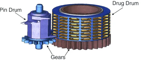
Figure 3.1 Drug and pin drums in the proposed Draper/MEEI ophthalmic drug delivery device...37
Figure 3.2 Bottom view of the two drums on the Draper/MEEI device ... 38
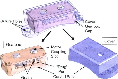
Figure 3.3 O verview of gear device... 41
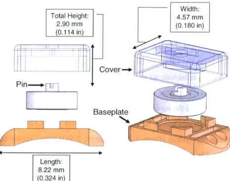
Figure 3.4 Dimensions of gear device, exploded view ... 41
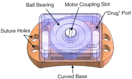
Figure 3.5 Overview of ball bearing device... 42
Figure 3.6 Dimensions of the ball bearing device, exploded view ... 43
Figure 3.7 M echanical testing apparatus. ... 46
Figure 3.8 Geometry for calculation of appropriate wire length on the motor shaft adaptor...47
Figure 3.9 Secondary torque testing apparatus schematic ... 49
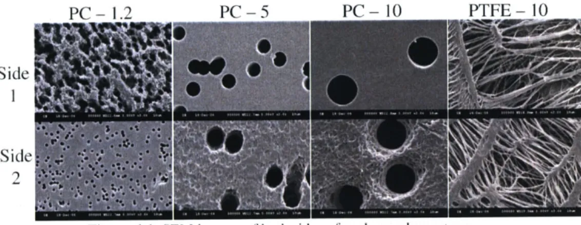
Figure 4.1 SEM images of both sides of each membrane type ... 52
Figure 4.2 Schematic of cell culture apparatus for investigating cell migration through a membrane...53
Figure 4.3 Average number of cells per square millimeter on the seeded side of each membrane...54
Figure 4.4 Median number of cells per square millimeter on the non-seeded side of each membrane ... 54
Figure 5.1 Membrane assembly apparatus schematic ... 59
Figure 5.2 Pre-implantation photographs of a typical gearbox ... 59
Figure 5.3 Pre-implantation photographs of a typical gearbox with membrane...60
Figure 5.4 Pre-implantation photographs of a typical ball bearing device: (a) top, (b) bottom, (c,d) sides.... 60
Figure 5.5 Surgical procedure for implanting test device into a rabbit...62
Figure 5.6 Photographs of gear devices on the rabbit eye immediately before removal...64
Figure 5.7 Stereomicroscope photographs of gear devices after 2 week or 10 week times...65
Figure 5.8 Stereomicroscope photographs of the internal view of long term gear devices...66
Figure 5.9 Stereomicroscope photographs of the three BB-l devices after implant ... 67
Figure 5.10 Sections of the sclera beneath one SSM-s device ... 68
Figure 5.11 Sections of the sclera beneath long-term devices...68
Figure 5.12 Sections of the conjunctiva above devices ... 69
Figure 5.13 Sections from tissue residing inside devices after 10 weeks...70
Figure 5.14 Sections of the PTFE membrane from the base of one SSM-1 device...70
Figure 5.15 Speed effects during pre-testing for three long-term groups. ... 71
List of Acronyms
AISI American Iron and Steel Institute
AMD Age-related macular degeneration
ASTM American Society for Testing and Materials
BRB Blood-retinal barrier
CMV Cytomegalovirus
CNV Choroidal neovascullarization
CP Commercially pure
EDM Electrical discharge machining
ePTFE Expanded polytetratluoroethylene
EVA Ethylene-vinyl acetate
FBGC Foreign body giant cell
FDA Food and Drug Administration
GDD Glaucoma drainage device
GDNF Glial cell line derived neurotrophic factor
IOP Intraocular pressure
ISO International Organization for Standardization MAI Poly(rmethyl acrylate-co-2-hydroxyethyl acetate)
MEEI Massachusetts Eye and Ear Infirmary
MEMS Microelectromechanical systems
NF National Formulary
PBS Phosphate bulered saline
PC Polycarbonate
PEDF Platelet derived growth factor
PGA Polyglycolic acid
PLA Polylactic acid
PLGA Poly(lactic-co-glycolic acid)
PMMA Polynethylmethacrylate
PTFE Polytetrafluoroethylene
PVA Polyvinyl alcohol
RPE Retinal pigment epithelium
SEM Scanning electron microscope
siRNA Small interfering RNA
USP United States Pharmacopeia
VEGF Vascular endothelial growth factor
Chapter 1: Introduction
Diseases of the posterior eye affect many thousands of patients, with 200,000 new cases of exudative age-related macular degeneration (AMD) alone each year [1]. There has been a recent increase in the number of therapeutics available to treat these diseases. However, a common challenge remains: what is the best method of drug delivery to the back of the eye?
Clinicians and researchers have tackled this problem in a variety of different ways. Current treatments for macular degeneration mainly require periodic injection of drug, currently either an aptamer or an antibody, into the interior of the globe. Research has also been conducted using degradable drug-loaded polymer constructs that are surgically implanted or injected via syringe into the eye for sustained release of therapeutic. Additionally, methods for passive or aided drug diffusion across the eye wall have also been investigated. These include the use of degradable polymers, but also refer to electrically driven drug diffusion known as lontophoresis.
While promising, these methods are associated with several risks. First, any injection into the eyeball has the potential to create an infection or other complications. With the newest drugs for macular degeneration, injection is required every 4 or 6 weeks, adding a renewed risk with each treatment. Every intraocular injection requires an office visit by the patient, and compliance for this time consuming, unpleasant activity presents a formidable challenge to physicians. Any intraocular implant comes with additional complications due to the surgical procedure and disruption of the intraocular materials and pressure.
While transscleral diffusion of drug has shown promise, few long-term, implantable solutions for the back of the eye have been proposed for placement outside of the eyeball. Degradable polymer devices for this application are typically used for delivery of drug on the order of days or weeks as opposed to months. Extending this lifetime requires attention to protection of the drug from degradation before its release. Simple injection of drug or drug-loaded microspheres into this space runs the risk of drug dissipation away from the localized area of interest.
With the latter problem in mind, Draper Laboratory and Massachusetts Eye and Ear Infirmary (MEEI) have proposed an implantable mechanical device designed to deliver small, timed bursts of drug directly to the external surface of the eyeball. This device would attach to
the sclera on the back of the eye and would house drug in sealed internal chambers. It would allow fluid communication and drug diffusion through a window in its base, locating the therapeutic directly to the eye surface for transscleral diffusion. In creating this pathway for the drug, the original design calls for exposing the internal device elements to the fluid, molecules and cells in the eye's external environment.
As with any implanted foreign object, the body's natural immune response will tend to attack and surround the implant with protein deposition and fibrous tissue. Because of the miniature size of machine elements such as gears and ball bearings in such a device, even a small amount of fibrous tissue infiltration could disrupt its function. A permanent, metallic device of this type also has the potential to damage surrounding ocular tissues.
This thesis investigates the biocompatibility - both the effects on the body and the effects on the device - of this type of implant. Evaluation focuses on a long-term animal model testing a set of smaller, simpler devices that contain the moving elements of the proposed drug delivery apparatus. These test devices mimic certain key elements of the Draper/MEEI device:
" Curved baseplate to mate with the eye surface
" Ports in the baseplate for drug and fluid communication " Relative part size
* Types of moving elements inside the implant - gears and ball bearings " Materials selected for fabrication
* Attachment of the device to the scleral surface of the animal's eye
The novel application of a porous membrane to restrict cell entry into the device interior was also considered. Material and pore size selection were chosen after cell culture studies on a set of appropriate membranes. Fibroblasts were seeded onto one side of each membrane and their ability to migrate to the non-seeded side was evaluated. The ideal filter blocks the passage of these cells, but would also be porous enough to allow drug to pass through freely. The
membrane chosen from this study was applied to a subset of the implanted devices.
Torque testing of the devices before and after implant identified changes in device function while implanted. Tests utilized a small motor to apply force to the devices' rotating elements and a dynamometer beneath the devices to record applied torque. From these measurements, the mechanical effects of any protein deposition, inflammatory cells or fibrous tissue inside the device during implant were determined. The effects of the device on
surrounding tissues were also in question. Eye wall tissue from beneath the device, soft tissue covering the device and any invading tissue into the device were preserved and investigated histologically. Qualitative analysis revealed the cell and tissue types present.
In this work, the feasibility of implanting a long-term device with miniature scale, exposed metallic moving parts has been explored for attachment external to the posterior eye. The particular drug delivery system investigated in this thesis was designed with macular degeneration as its target disease and related, recently developed drugs as its target therapies. However, other posterior eye diseases present similar challenges for effective delivery of drug, and similar mechanical device designs could be proposed for placement in this location. Therefore, future drugs and device designs for any other posterior eye conditions may also benefit from the investigation presented here.
Chapter 2: Background
2.1 Eye Anatomy
2.1.1 Overview
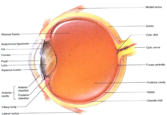
The globe of the eye has a roughly spherical shape, measuring approximately 24mm in diameter in humans [2]. Its wall consists of three compact layers known as the outer, middle and inner coats or tunics. As shown in Figure 2.1, the sclera and cornea comprise the outer layer. The middle, or uveal, coat consists of the choroid layer of blood vessels, the ciliary body, which
supports the lens, and the iris. Finally, the retina is the innermost, nervous cell-rich layer [3]. The interior space of the eye is divided into three chambers. The first, bounded by the cornea, the lens and parts of the iris, ciliary body and sclera, is the anterior chamber. This region is filled with the aqueous humor, secreted by the ciliary body into the cavity and continuously pumped out. The second chamber is the posterior, bounded by the iris and the suspensory ligaments that extend from the ciliary body to the lens. The remaining eye volume forms the vitreous chamber or posterior cavity, named for the vitreous humor, a gel-like collagen and mucopolysaccharide substance found inside [2].
--- Medial rectus
Sclera
Vitreous humor - -- Optic disk
Suspensory ligaments
Iris --- -Optic nerve
Cornea---- - --Pupil Lens Aqueous humor Fovea centralis Anterior Posterior cavity cavity Posterior Retina -chamber -__- Chorold coat Ciliary body Lateral rectus
Figure 2.1 Transverse section of the eye, top view. From Hole's Human Anatomy and Physiology, 8th ed., by Shier
D., Butler J, and Lewis R., WCB McGraw-Hill: 1999. Reproduced with permission from the McGraw-Hill
2.1.2 Outer Tunic
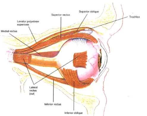
On the anterior side of the outer tunic, the cornea presents a transparent surface for passage and initial focusing of light. Its transparency stems from highly ordered layers of connective tissue and a sparse population of cells. Covering the remaining 5/6 of the globe's surface and serving both to protect the eye and to accommodate muscle insertion is the sclera [3]. It consists of three roughly defined layers: the episclera, the sclera proper and the lamina fusca [4]. The lamina fusca is the innermost layer and contains many pigmented cells similar to those in the choroid layer. The outermost layer is the episclera, a loose membrane containing many blood vessels [5]. It also serves as the insertion site for the six extrinsic muscles, which allow for motion of the globe. As shown in Figure 2.2, these are the superior, inferior, medial and lateral rectus muscles and the superior and inferior oblique muscles [3].
Superior oblique Trochlea Levator palpebrae superiols Medial reclus Lateral reclus (cut) Inferior rectus Inferior oblique
Figure 2.2 Lateral view of the eye in its orbit. From Hole's Human Anatomy and Physiology, 8th ed., by Shier D.,
Butler J, and Lewis R., WCB McGraw-Hill: 1999. Reproduced with permission from the McGraw-Hill Companies.
Between these two layers, tightly woven collagen fibers continuous with those of the cornea form the sclera proper. Near the cornea, these fibers run anterior to posterior; at the equator, they run circumferentially; in the posterior portion of the eye, they run at right angles to each other. In humans, this tissue ranges in thickness from about 0.7mm near the cornea to 0.5mm near the equator to 1.0mm in the posterior. The sclera proper has a low degree of
vascularization [2]. Both fibrous and pigmented cells are found throughout the sclera, and a layer of squamous cells line its outer surface [5].
At the junction between the sclera and the cornea is a concave region called the limbus (or corneoscleral junction). Within this region, a network of porous structures directs fluid pumped from the anterior chamber to the Canal of Schlemm, immediately posterior to the limubs. Also called the scleral venous sinus [3], this canal leads fluid to the venous system via several channels [4].
2.1.3 Middle Tunic
The majority of the uveal layer is made up of the choroid coat, a dark layer of blood vessels that supplies the adjacent retina [2]. Veins in the outer region of the layer split into capillaries near the retina. The choroid coat is tightly bound to the sclera in only five locations: near the optic nerve where the arteries enter the eye, and at the exit sites of each of the four major veins [4].
At the front of the eye, the choroid layer continues forward to become the ciliary body. The former extends muscles to the suspensory ligaments, which are in turn responsible for controlling the curvature of the lens. The lens, along with the cornea, controls the shape of light as it enters the globe. It is composed of elongated cells and covered by the lens capsule, both allowing for transparency to the entering light [2].
The iris connects to the anterior side of the ciliary body. Its circumferential and radial muscles [3] allow it to regulate the aperture of the pupil, thereby blocking or allowing differing amounts of light to pass into the eye. Due to its location and geometry, it also regulates the amount of fluid flow between the anterior and posterior chambers of the globe [2].
2.1.4 Inner Tunic
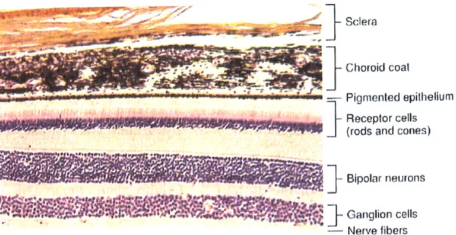
After light passes through the pupil and is refracted by the lens, it travels to the photoreceptor cells of the retina, which lies directly inside the choroid layer. The outermost layer of the retina is Bruch's membrane, which separates the retina from the choroid layer. Attached to this membrane is the retinal pigment epithelium (RPE), a layer of hexagonal cells held together by tight junctions. This epithelium is therefore responsible for maintaining the blood-retinal barrier (BRB) [6]. The RPE in turn connects to the rods and cones - black and white or color photoreceptors, respectively. Continuing towards the inside of the eye, the rods
and cones connect to a mesh of nerve cells and fibers, then to a layer of only fibers. The latter carry nerve signals to the optic nerve and on to the brain for processing [2]. Figure 2.3 shows a cross section through eye wall tissue.
Sclera
- Choroici coal
Pignmented epithelium
______________________________________________ Receptor cells
(rods and cones)
Bipolar neurons
S]-
'WGanglion cells
- Nerve fibers
Figure 2.3 Histological section of the tissues in the eye wall. From Hole's Human Anatomy and Physiology, 8th
ed.. by Shier D., Butler J, and Lewis R., WCB Hill: 1999. Reproduced with permission from the McGraw-Hill Companies.
In primates, an approximately 5-6mm region in the posterior of the retina is known as the macula, at the center of which is the fovea. This area is responsible for the central 15-20 degrees of vision [6]. The cells in this area are long, slender and tightly packed. In the fovea, the photoreceptors are almost entirely cones [2]. The entire macular area can be broken into several concentric rings. Starting from the center, they are the umbo (center point of the fovea and the thinnest area), the foveola, the outer margins of the fovea, the parafovea (thickest area) and the perifovea [6].
2.1.5 External Structures
The globes are situated in two bony orbits of the skull. In humans, these orbits are approximately pyramid shaped and are each angled about 45 degrees laterally from center, with the medial walls roughly parallel to each other. The optic nerve and ophthalmic artery exit through the optic foramen in the back of each orbit [7].
Each eye is shrouded by connective tissue called Tenon's capsule, from which emerges a medial and a lateral check ligament spanning from the eye to the periosteum covering the orbital bones. This set of three tissues comprises the suspensory ligament and is largely responsible for supporting the eye. Other similar ligaments run above and below the eye, though they are less
consistent between individuals. All space between connective tissue in the orbit is filled with fatty tissue, serving to cushion and support the eye and helping maintain its position in the orbit. A layer of connective tissue covers all structures, including this fatty cushion [7].
At the front of each globe is a set of eyelids (Figure 2.4), called palperbrae, each consisting of four layers: skin, striated muscle, connective tissue and conjunctiva. The muscles serve to open and close the eyes, and the connective tissue contains glands that secrete lubricating oil. The conjunctiva is a mucous membrane that folds between the eyelid and the globe [3]; the palpebral conjunctiva section lines the eyelid and the blulbar conjunctiva section rests on the globe. These regions are connected by a loose area of conjunctiva, which forms conjunctival sacs near the equator of the globe [2]. Conjunctiva consists of an epithelial layer that contains mucous producing cells, which rests on a stromal or connective tissue layer that attaches to the eyelid or rests on the eyeball [8].
Tendon of levator palpebrae superioris Eyelid Fibers of Tarsal V ands Comnea Conjuncliva
Figure 2.4 Sagittal section of the closed eyelids and anterior portion of the eye. From Hole's Human Anatomy and Physiology, 8th ed., by Shier D., Butler J, and Lewis R., WCB McGraw-Hill: 1999. Reproduced with permission
2.2 Eye Pathology
2.2.1 Disease Overview
Many diseases that affect the tissues of the eye present potential challenges for drug delivery and may benefit from implantable solutions. A variety of bacterial, viral and fungal infections can affect most structures of the eye, originating from either external or blood borne sources. These have been treated with pharmaceuticals, which have varying degrees of success [9]. Other than infections, common diseases that can be treated from the front of the eye are glaucoma and cataracts. In the posterior eye, conditions often present treatment challenges complicated by the inaccessible location and the need for long-term treatment. These diseases mainly affect the retina, the RPE and the choroid coat.
Glaucoma is defined by an increase in intraocular pressure (IOP) due to several possible causes for increased resistance to aqueous humor outflow. A chronic increase in IOP can lead to damage of surrounding tissues, including corneal edema, necrosis of the iris and most devastatingly, damage to the optic nerve [10]. Treatments for this disease therefore focus on reduction of the IOP, namely in the anterior chamber. Initially, a variety of drugs in drop form may be used to control production of aqueous humor or facilitate its removal from the anterior chamber. In cases when drug treatments or surgery are insufficient, a glaucoma drainage device may be implanted. Typically, these devices consist of a tube inserted into the anterior chamber to direct fluid out to a plate sutured onto the sclera in the subconjunctival space. Variations include addition of a pressure valve inside the tube, drainage of fluid to the limbus area and fluid drainage directly to the canal of Schlemm [II].
Cataracts affect the transparency of the lens. While many causes and types do exist, cataracts are generally areas of opacity in the lens and often grow with time [12]. Despite the severity, it is the most common treatable cause of blindness in the world. It is most frequently treated by surgical removal of the damaged natural lens and insertion of a prosthetic lens in its place. This new lens may be inserted in one of three locations: between the cornea and iris, in the pupil or behind the iris. Intra ocular lenses are usually constructed of polymethylmethacrylate (PMMA) and are designed with a central transparent "lens" portion with
In the posterior eye, macular dystrophies are genetic conditions causing loss of vision, often by change in the RPE or choroid layers. Stargardt disease, for example, shows yellow deposits in the macula, with RPE atrophy in later stages. Potentially affecting both retina and choroid, retinitis pigmentosa is defined as a progressive loss in rod and then cone function, especially diminishing peripheral vision [14]. Some of these diseases are also complicated by choroidal neovascularization (CNV), or new blood vessel formation in the choroid layer, causing vision loss in diseases such as Sorsby fundus dystrophy and Best vitelliform macular dystrophy
[15].
Macular edemas are characterized by a breakdown of the BRB, allowing fluid accumulation posterior to the retina. Diabetic macular edema, for example, begins with a change in the permeability of the barrier, and fluid leakage can take place at one or many foci. Central and branch retinal vein occlusion is often associated with cystoid macular edema whereby the barrier breaks down near the retinal veins [15].
One severe, acute complication of macular edema is retinal detachment, a lifting or pulling of the retina from its underlying layers. Most commonly the cause, a tear in the retina allows fluid to enter the subretinal space, separating the retina from the underlying tissues. In other cases, either an internal fibrous membrane pulls away the retina or a fluid pocket builds behind the retina to push it away [16]. While silicone oil has been used inside the vitreous cavity to push the retina against the globe, retinal detachments are often repaired by implanting a scleral buckle onto the outside of the posterior of the eye. This typically flexible block of material serves to indent the vitreous cavity to meet the new location of the retina. The technique of suturing a buckle to the sclera dates back to the 1930s, and success is reported in about 90% of cases [13, 17].
Associated with retinal detachment is proliferative vitreoretinopathy, a condition whereby a variety of benign cells proliferate in the vitreous cavity and line the detached retina on both sides. A variety of drugs have been used to treat this condition, mostly aimed at the prevention of one of the disease stages. Steroids and other anti-inflammatory drugs encourage the integrity of the blood-retinal barrier, while drugs like 5-Fluorouracil (5-FU) discourage cell proliferation. Because half-lives of these drugs are relatively short after intravitreal injection, other delivery methods have been investigated such as slow release polymeric delivery vehicles [9].
2.2.2 Age-Related Macular Degeneration
Of the macular edemas, exudative AMD is very common and is the leading cause of blindness in people over 55 in the United States [18]. Characterized by a loss of central vision, the cases of all AMD fall into two subgroups: atrophic (dry), which may lead to exudative (wet). The former is known for its degenerated RPE and progressive damage to photoreceptors, while the latter is much more severe due to CNV [1, 19]. In fact, the wet form accounts for only 10% of AMD patients, yet it is responsible for 90% of all severe vision loss cases [20].
The earliest dysfunction in AMD is the age-related degeneration of the RPE in the macular region. Damage to this cell layer leads to improper maintenance of the blood-retinal barrier, poor chemical processing during the visual cycle, and incomplete uptake of photoreceptor cell waste. This cascade is driven by the insufficiency of new RPE cells, which allows for the accumulation of lipofuscin granules that contain cytotoxic molecules. Common to all AMD cases is the deposition of drusen, yellow material consisting of RPE remnants and a variety of proteins. These deposits form between the RPE and Bruch's membrane. It is both the resulting mechanical displacement of tissue and the associated inflammatory response that then cause damage to the overlying photoreceptors [1].
As an AMD case progresses to the wet form, new blood vessels stem from the choroid layer with a tendency to leak through the BRB and form scars, leading to severe vision loss. Many theories have been investigated as to the instigating factor for CNV formation, including thickening of Bruch's membrane by drusen, inflammatory degeneration of Bruch's membrane and reduction of retinal blood flow due to scleral stiffening [19].
All of these conditions may lead to an increase in the relative amount of vascular endothelial growth factor (VEGF), which has been implicated in a wide variety of diseases showing neovascularization. VEGF is a necessary factor for new vessel formation, as it encourages endothelial cell reproduction and increases vascular permeability for new branching [19]. In the healthy choroid, VEGF is balanced by the anti-angiogenic pigment epithelium derived factor (PEDF). In wet AMD, however, VEGF is produced in relatively higher concentration, which eventually leads to fluid accumulation in the retina and vision loss [I].
There is no current treatment for dry AMD, but several treatment methods have been used or proposed for wet AMD. Some involve the chemical or thermal disruption of new vessel formation - photodynamic therapy, transpupillary thermotherapy, thermal laser photocoagulation
and low dose radiation therapy. Surgical methods of removing CNV, translating the retina away from damaged areas and transplanting healthy RPE have also been used [1, 21, 22]. Additionally, pharmacologic agents such a steroids, small interfering RNA (siRNA) and PEDF are being developed [ 1, 19].
Recently, the most promising treatments are the anti-VEGF agents pegabtanib, bevacizumab and ranibizumab. Pegabtanib sodium (Macugen@) is a short pegylated, modified RNA oligonucleotide that binds to only the major VEGF isoform responsible for CNV. With 0.3mg intra-ocular injections every 6 weeks, trials showed stabilized vision in 70% of patients [23]. On the market to treat metastatic colorectal cancer, bevacizumab (Avastin@) is a full-length monoclonal antibody to VEGF and has been proposed for off label use to treat CNV. A shorter, 48kDa antibody fragment, ranibizumab (Lucentis@), has more recently shown the greatest promise to treat this disease. By design, this drug binds to and neutralizes all forms of VEGF [24]. Several clinical trials with this drug have shown approximately 95% of patients experience a minimal loss of vision, with approximately 75% maintaining or increasing visual acuity. Trials were conducted with 0.3 or 0.5mg doses injected intravitreally once every four weeks for 1-2 years [1, 19, 25]. This drug received FDA approval in July 2006 for monthly dosing of 0.5mg [26].
2.3 Biocompatibility
2.3.1 General Considerations
With any implanted device, the interface between the foreign object and the body tissues must be examined and considered. The body has a natural healing process for its wounded tissues, which are typically unavoidable in an implant surgery. The body will also mount an attack on any material that it considers non-self, which may change the function or properties of a device. Further, the chemical and mechanical nature of device materials in the body environment may contribute to irritation of surrounding tissues. It is both device effects on the body's health and body effects on the device function that define biocompatibility as used in this thesis. As stated by Dee, Puleo and Bizios: "Biocompatibility, therefore, must account for the interactions between tissues and biomaterials. The use of the prefix 'inter' implies that not only can biomaterials affect biological responses, but also the milieu of the body can affect materials [27]."
Immediately after being placed in the body, an implant is likely to adsorb the proteins abundant in all tissues and body fluids. Proteins may further unfold upon adsorption due to the changes in their chemical environment, often adding to their bonding strength. Less stable proteins are more likely to unfold in this case. Any adsorbed protein may in turn attract antibodies, other proteins or leukocytes [27].
Biomaterials can influence certain protein adsorption by their surface properties. Rough topography provides increased surface area for protein attachment. Chemical composition of the material will also determine the types of interactions possible with local proteins. For example, hydrophobic surfaces are more likely to bind protein than hydrophilic ones. Surface potential can encourage adsorption of charged molecules and will affect the distribution of ions in the surrounding solution. As the first proteins bind to a material, they may do so in a similar manner due to the availability of surface area on the material. As more bind, however, space limitations force proteins to change conformations. Any protein unfolding or shielding of active sites will likely alter the molecule's function [27].
Implantation usually causes a wound in the patient, to a varying degree. The body will then naturally try to heal that wound, but will likely be unable to remove the offending foreign object. Natural wound healing consists of coagulation, inflammation, repair and remodeling. The coagulation cascade can be initiated by the intrinsic pathway - platelet contact with non-healthy vasculature or foreign substance, or by the extrinsic pathway - release of tissue thromboplastin after tissue trauma. Both cascades lead to the formation of a fibrin clot around the damaged area or foreign material. Even an implant that does not contact blood can encourage this series of events if it allows adsorption and activation of a protein called factor XII
[27].
Subsequent dilation of the capillaries brings greater blood flow to the area, accompanied by an increase in capillary permeability. Redness and swelling in the area results [28]. Inflammatory leukocytes are then encouraged to move towards the damaged site with the duty of destroying any invading irritation by releasing chemicals such as lysosymes. These cells include
tissue macrophages, circulating monocytes, and circulating neutrophils [27]. The dead space
alone, inevitably created by placement of an implant, will encourage migration of macrophages to the body-device interface [29].
In the natural case, mitosis of inflammatory cells forms a granulation tissue in the area, which is later replaced by collagen molecules and other necessary elements for new, healthy tissue. In the situation of an implant, however, the inflammatory cells do not have the capability to destroy the foreign object chemically or by phagocytosis, leading to a situation known as frustrated phagocytosis. Macrophages in this case will replicate and fuse together into "foreign body giant cells" (FBGC's) around the material, isolating it from the body. Rather than remodeled tissue, new fibroblasts are recruited to form a fibrous capsule around the material, creating a more permanent wall between the foreign object and the body [27]. This process generally progresses for 1-2 weeks after implant and then enters a chronic phase. Later stages tend to show a fibrous tissue capsule with relatively few, spindle shaped fibroblasts. Materials that leach particles or ions may be toxic to cells or surrounding tissues and will typically be surrounded by an increased number of inflammatory cells during chronic phases [28].
A variety of conditions as well as material and implant properties may affect the extent to which the foreign body response will occur. These include the site of implantation, the availability of blood supply in the area, any mechanical forces the device creates, chemical release from the materials and pre-existing pathologies or infections. One report recently showed that solely a dead space or low pressure area in connective tissue as small as 6[m encourages fibrous tissue formation locally around a material [30]. Thinner capsules will form around implants that are round, static, chemically stable, and that have straight sections and textured surfaces [27]. Capsule thickness generally increases when there is relative motion between the device and the surrounding tissue. Extreme cases may lead to a fluid-filled sac around the entire implant, or around sharper edges [28].
2.3.2 Biocompatible Materials
Despite these challenges to implantation, a variety of materials have historically been used for long term residence in the body. These include metals, ceramics and polymers, and they fall into one of four categories with respect to their properties in vivo: inert, interactive, viable or replant [28].
The first recorded use of a metal implant was by Petronius in 1565, who used a gold plate to repair a cleft palate. Use of gold, iron, bronze and brass materials continued to be developed through the 1860s at which time sterile surgical techniques were developed. With this change, it
became apparent that different materials (e.g., platinum, gold, silver, lead, zinc, aluminum, copper, magnesium) produced different effects in the body. Through the early 1900s, the need for corrosion resistant materials was identified as important for future implants [31].
More recently, this list of needs has expanded beyond corrosion to address any adverse effects caused by a device in the body. While a material's biocompatibility does depend on the situation in which the device is implanted, a material that for example is toxic to surrounding cells is typically rejected for use. The Food and Drug Administration (FDA) requires that devices be subjected to testing for all potential adverse effects on the body by its constituent materials. Tests should be selected from the battery developed by the International Organization for Standardization (ISO), listed under ISO 10993. The selection process should take into consideration the material properties as well as the nature of the material's contact with the body. The ISO 10993 tests include "acute, sub-chronic and chronic toxicity; irritation to skin, eyes and mucosal surfaces; sensitization; hemocompatibility; genotoxicity; carcinogenicity; and, effects on reproduction including developmental effects." Additional tests may be necessary to gain FDA approval depending on the situation [32].
In addition to these requirements, materials in implants are chosen for their other properties such as mechanical strength, or ability to react in a particular way with surrounding tissues. Metals have been used extensively in implants and are most useful for their mechanical properties [31]. The four most common metals used in implantable devices are stainless steel (American Iron and Steel Institute (AISI) 316L, or American Society for Testing and Materials (ASTM) F138,139), cobalt-chromium-molybdenum alloy (ASTM F799), titanium (commercially pure (CP) grade 4), and titanium-aluminum-vanadium alloy (Ti6AI4V) [27].
Type 316L stainless steel (18CrI4Ni2.5Mo) is a vacuum-melted low carbon variation on the standard 3 16 material. It has a maximized pitting corrosion resistance due to its chemistry, and the vacuum process adds to its cleanliness. This stainless steel has been used in applications such as bone screws and pins, bone plates, joint replacements, wires and meshes for orthopedic applications and casings for laryngeal prosthesis and pacemakers [31].
Titanium gains its corrosion resistance from the oxide layer that forms on its surface, which leads to lower corrosion compared to stainless steel or cobalt-chromium alloys. It has been shown to have minimal fibrous tissue response as compared to these other metals. Titanium is manufactured as CP or in alloy form. CP grades are dependent on the carbon and
iron content, where the higher purity has lower strength and hardness but higher corrosion resistance. Alloys used for medical applications are made with aluminum and vanadium or niobium. Ti6AI4V has generally higher strength and fatigue limit than the commercially pure metal. On titanium, however, if the oxide layer on the surface is worn away, any metal-metal contact leads to high friction and wear rates. Titanium and alloys have been used for implants such as pacemaker cases, pump housings, dental implants, craniofacial implants, hip and knee joint replacements and screws and staples for spinal surgery [27, 3 1].
A wide variety of polymers have also been used in implantable devices. These range from biodegradable to chemically inert materials. Of the latter, polytetrafluoroethylene (PTFE, Teflon@) has been used extensively in the body, especially for vascular grafts [31]. PTFE was created in 1938 at DuPont and consists of a carbon backbone bonded to fluorine atoms. Its compact structure and minimal molecular branching contribute to its high density, low modulus and low coefficient of friction. The material is preferable for in vivo applications due to its extreme resistance to chemical reactions. As a bulk material in vivo, a minimal amount of tissue reaction occurs, though the particulate or powder forms of PTFE are highly reactive. PTFE can also be expanded (ePTFE) to form a microporous structure, which is advantageous for some applications [33].
Ceramic materials have also been used for a variety of applications. One of these is zirconia. Most often stabilized with yittrium oxide (Y203), it has relatively high strength and
fracture toughness and can be polished to a very smooth surface. This material has been largely used for femoral heads in hip replacements and has been shown to produce far less wear debris in those implants as compared to metal heads. Degradation of this material in body fluids has been of concern, and newer zirconia/alumina composites are being developed to solve this problem [34].
2.3.3 Device Bioconpatibility
In order to be considered biocompatible, an implanted device must perform as is suitable for the function and environment. Because of this vague notion, it is necessary to consider the biocompatibility of every implant separately in its intended environment [35]. Recent studies have investigated biocompatibility of permanent sensor or drug delivery implants made using microelectromechanical systems (MEMS) technology in silicon. Important factors for these
applications include the potential toxicity or inflammatory response due to the less used silicon as a biomaterial. Also, fibrous tissue occlusion of the sensor or of the delivery ports may disrupt the function of the device. Yang et al. investigated the biocompatibility of a silicon-based pressure sensor by implanting several percutaneously along rabbit lumbar muscles for 1, 4 or 12 weeks. Results showed that granulation tissue formed around the devices, slowly replaced by fibrous tissue. With time, capsule thickness and density of inflammatory cells decreased, while fibroblast density increased. Despite this reaction, the authors concluded that the device was "biocompatible" for their application [36].
Similarly, Voskerician et al. have studied the biocompatibility of their drug delivery device created with gold, silicon, silicon dioxide, silicon nitride and SU-8 photoresist. Testing materials separately, coupons of each inside an AISI 3 10 stainless steel cage were implanted subcutaneously in a rat. After 4, 7, 14, and 21 days, the number and types of cells present around the materials were identified. All materials were associated with an acute inflammatory period, though the number of macrophages and FBGC's decreased over time. FBGC's were found to cover the drug wells in a fabricated mock device, though it was unclear whether the wells were intact or opened in these cases. In a similar experiment, this group tested the local effects of gold salts produced after electrical activation of each well. Analysis indicated that there was an increase in the inflammatory response after the voltage was applied, though the cell density cleared by 21 days [37, 38]. These studies focused on only the short-term effects of implanting this device.
2.3.4 Scleral Materials and Devices
As discussed in Section 2.2.1, two devices have been used regularly on the sclera: the scleral buckle and the glaucoma drainage device. Their biocompatibility varies in nature depending on the materials used and their design. Both devices are intended to reside on the sclera for periods of years.
Scleral buckles are solid, flexible bands that are sutured to the sclera in order to indent the globe towards a detached retina [17]. Absorbable materials for this device include autogenous tendon, absorbable gut and pigskin gelatin [13]. More typically, however, non-degradable silicones and hydrogels are used in the form of porous sponges, smooth blocks or encircling bands [17]. They are designed with soft, flexible properties so as to cause minimal
erosion to the sclera during long-term attachment. Silicones encourage formation of a surrounding fibrous capsule, which has the advantages in this case of securing the device and strengthening the sclera [13]. This tissue mass may, however, also prevent eye motility. Hydrogel buckles were introduced in the 1980s and were most commonly based on poly(methyl acrylate-co-2-hydroxyethyl acrylate) (MAI and MIRAgel). This material, however, has been associated with buckle failure due to excessive swelling and subsequent material fragmentation [17]. These effects may be due directly to FBGC granuloma on the periphery of the device. Comparing excised silicone and MIRAgel buckles, the silicone buckles were more often associated with bacterial infection and the solid forms more associated with scleral erosion as compared to the sponge forms [39].
Glaucoma drainage devices (GDD's) have been used to relieve fluid pressure in the anterior chamber. Several versions exist, though most consist of a tube that resides in the chamber on one end and leads to a plate sutured to the sclera on the other end. The plate anchors the implant and allows for fluid to be drawn out from the tube into a bleb, to then dissipate in the subconjunctival space. Tube materials have historically been made from silicone rubber or nylon; plate materials typically include PMMA, polyethylene and silicone rubber [40].
While silicone rubber has been shown to be effective as a scleral buckle, for GDD's inflammation and fibrous encapsulation around the plate directly affect the drainage function of the device. With all GDD's, this effect is the leading cause of failure [11]. Additional complications include erosion in tissue around the system [40], infection and decreased intraocular motility [41]. While it may be the aqueous humor that stimulates fibrous tissue formation [11], both the micro motion of the plates on the eye surface and choice of material have been suggested as the cause of most complications [13]. The more rigid materials may exhibit more micro motion against the tissues, which may in turn increase the inflammatory response. Adding windows for tissue ingrowth to these materials may anchor the device, reducing the motion and decreasing the eventual fibrous capsule thickness [11]. Implantation of solely the plate results in a layer of avascular fibrous tissue around the material that remains consistently after 4 weeks of implantation. Ayyala et al. showed that polypropylene encourages much greater fibrous tissue formation than silicone rubber plates [42]. Boswell et al. showed that a novel ePTFE plate with different geometry encouraged a thinner, less dense fibrous capsule as compared to the silicone [43].
2.4 Local, Implantable Drug Delivery
2.4.1 Drug Delivery Challenges
Systemic delivery, whether by ingestion or injection, is a routine method of transporting medication to affected areas in the body. This method proves to be challenging or dangerous for many current or newly developed therapeutics. Ingesting a drug requires that it be protected against digestive actions in the stomach, that it be capable of crossing the intestinal wall and that it pass through the liver without losing its activity before entering systemic circulation. Injected drugs do bypass the digestive tract, but needle use is impractical for many applications [44, 45].
In response to these hurdles, alternative methods of systemic drug delivery have been developed or proposed. These include methods of drug inhalation. They also include transdermal delivery, which may allow for either systemic delivery or for local delivery to tissues near the skin surface. Transdermal delivery has been investigated by diffusion from a patch, by adding a current to drive drug through the skin, by using ultrasonic waves to disrupt the outer layer of skin, allowing drug to pass through [44, 45] or by first piercing the top layer of skin with microneedles [46, 47]. Additionally, wearable devices are also on the market for continuous, controlled, systemic drug delivery. One such device is an insulin pump made by Medtronic, consisting of a small, wearable control box and drug reservoir. This cartridge connects to a small tube, inserted on one end under the skin [48].
Regardless of these newer methods, however, systemic delivery for many treatments still requires a much larger amount of drug delivered to the entire body in order for a therapeutic amount to arrive at the intended location. Care must be taken to strike the optimal balance between toxicity to body tissues and inefficiency. In all systemic delivery, side effects to non-diseased tissue are of particular concern. [44, 49]. For example, because VEGF is a ubiquitous agent for controlling new blood vessel formation, the therapeutics for AMD (Section 2.2.2) could have a devastating effect on healthy vessels in the body if delivered systemically.
Furthermore, many new drugs are larger molecules such as proteins (commonly antibodies) and DNA which often have short half-lives in body fluids. These drugs can be designed with chemical side chains or embedded as part of a liposome to increase the time to degradation [9, 44]. However, a bolus injection of drug, even directly to the concerned area, will be cleared by the body and by diffusion. Depending on the treatment, all of these shortcomings
of current drug delivery require repeated dosing, which also encounters the unpredictable challenge of patient compliance.
2.4.2 New Local and Implantable Solutions
To counter these issues and to improve drug efficacy, a wide variety of drug delivery methods that are both local and implantable have been investigated and some brought to clinical practice. Simply stated by Moses, et al., with reference to chemotherapy drugs, "The drug itself becomes more effective when placed next to, and delivered directly to, its targeted tissue, and much higher local drug concentrations can be achieved compared to traditional approaches [49]." These new methods fall into two major categories: those using passively controlled polymer technology and those using programmable, actively controlled technology.
Early materials for the former were non-degradable polymer networks into which drug could be embedded for slow outward diffusion. This drug-carrier complex could then be implanted at the site of disease for localized treatment over a period of time governed by drug diffusion. Embedding drug in later materials like degradable lactic-glycolic acid copolymers
(polylactic acid - PLA; polyglycolic acid - PGA; poly(lactic-co-glycolic acid) - PLGA) allowed
for release by diffusion through the pores as well as by bulk degradation of the carrier itself [49]. These materials can be formed into a variety of shapes for insertion into specialized sites [50]. For example in a different material, chemotherapy agents have successfully been introduced into tumors in the brain via porous polyanhydride pads, allowing the drug to be delivered over three weeks [49].
Drug delivery from the commonly used bulk eroding polymers typically occurs in three phases. First is an initial burst of drug, second is a slow period of diffusion from the device and third is a final drug burst when the device is broken apart. While phase two is well regulated, the initial and final bursts are much less controlled. A newer device made of two polymers with differing degradation time constants has been shown to release ganciclovir to treat cytomegalovirus (CMV) over 200 days without the uncontrolled drug bursts [50].
In the category of actively controlled implantable drug delivery, MEMS technology has been used to create such devices. These implants consist generally of a series of sealed reservoirs, each containing a single dose of drug. To deliver, the seal on each reservoir is individually opened, using thermal and electrical means. Drug then diffuses into surrounding
fluid, landing first on the nearest tissues before having the potential to be cleared or dispersed through the systemic blood flow [51]. Recent in vivo work has shown relatively consistent delivery of lyophilized leuprolide acetate in a polyethylene glycol matrix using this system [52].
Though that application intended systemic delivery, this type of implantable device may also be very useful for localized delivery.
2.4.3 Ocular Drug Delivery Challenges
Drug delivery to the eye presents a distinctive set of challenges. Historically, only diseases external to the eye or in the anterior of the globe could be treated. Though treatments with drops or ointments are generally successful, even drug delivery to these highly accessible regions proves less than straightforward. A drug administered topically encounters many hurdles before having the opportunity to penetrate the cornea [4]. The anterior side of each globe is bathed in a constant flow of tear film consisting of lipid, aqueous and mucous layers [2]. Typical tear turnover is 16% per minute, most of which is cleared through the tear duct system. Due to this continuous wash, drugs applied to the tear film are generally only allowed to reach the aqueous humor I % of the time [53]. Aside from tear removal, proteins in the tear film may bind to drug molecules, prohibiting their diffusion through the cornea. Drug may also be metabolized here [4].
Once traversing the tear film, a drug must still be able to pass through the corneal epithelial layer in order to diffuse to the rest of the anterior chamber [4]. Topically applied drug may also diffuse through the conjunctiva and sclera to the internal tissues. This path is inefficient for most drugs, because it often diffuses first into the local capillaries, which then disperse it systemically. Drug that does diffuse through the anterior eye structures only proceeds to the posterior tissues in minimal doses [53].
Systemically delivered drugs for the posterior eye encounter the blood-ocular barrier, which allows only lipophilic molecules to pass [9]. Hydrophilic drugs will only diffuse from the blood stream when the BRB is disturbed, typically indicating that the related disease has reached its end stage and a drug therapy approach is less helpful [54]. Additionally, for some classes of molecules, such as organic acids, the RPE actively pumps drugs out of the ocular cavities and into the blood stream. Lipophilic molecules can easily diffuse back across the BRB once