Publisher’s version / Version de l'éditeur:
Construction Technology Update, 2008-03-01
READ THESE TERMS AND CONDITIONS CAREFULLY BEFORE USING THIS WEBSITE. https://nrc-publications.canada.ca/eng/copyright
Vous avez des questions? Nous pouvons vous aider. Pour communiquer directement avec un auteur, consultez la
première page de la revue dans laquelle son article a été publié afin de trouver ses coordonnées. Si vous n’arrivez pas à les repérer, communiquez avec nous à PublicationsArchive-ArchivesPublications@nrc-cnrc.gc.ca.
Questions? Contact the NRC Publications Archive team at
PublicationsArchive-ArchivesPublications@nrc-cnrc.gc.ca. If you wish to email the authors directly, please see the first page of the publication for their contact information.
NRC Publications Archive
Archives des publications du CNRC
Access and use of this website and the material on it are subject to the Terms and Conditions set forth at
Airborne sound insulation in multi-family buildings
Quirt, J. D.; Nightingale, T. R. T.
https://publications-cnrc.canada.ca/fra/droits
L’accès à ce site Web et l’utilisation de son contenu sont assujettis aux conditions présentées dans le site LISEZ CES CONDITIONS ATTENTIVEMENT AVANT D’UTILISER CE SITE WEB.
NRC Publications Record / Notice d'Archives des publications de CNRC:
https://nrc-publications.canada.ca/eng/view/object/?id=8e5c6e13-6dad-4018-a6c1-f3b2e840a726 https://publications-cnrc.canada.ca/fra/voir/objet/?id=8e5c6e13-6dad-4018-a6c1-f3b2e840a726The traditional approach to designing for noise control (sound insulation) in North American multi-family wood-frame buildings usually fails to address important aspects of how sound is transmitted. Canadian and U.S. building codes2have long considered only the Sound Transmission Class (STC) rating of the assembly separating adjacent dwellings—that is, the separating wall assembly when the units are side by side, or the floor/ceiling assembly when units are one above the other.
This approach does not ensure satisfactory sound insulation between units because it fails to consider flanking transmission, which is structure-borne sound transmission that bypasses the separating wall and travels through other building elements such as the floor, ceiling, or walls abutting the separating wall (also known as sidewalls).
Occupant satisfaction with the sound insulation between one’s own unit and other adjacent units is determined by the com-bined performance of the separating wall or floor assemblies and all the elements coupled to those assemblies. Controlling flanking transmission requires the proper selection and design of the complete build-ing system—i.e., all the structural elements, the fire blocks, the finishes, and the connec-tions at the juncconnec-tions of partition walls, floors and ceilings. In other words, it is the performance of the whole system and not just that of the separating assembly that will determine the sound insulation experienced by occupants.
By J.D. Quirt and T.R.T. Nightingale
This Update explains how an emphasis on system performance can achieve
good sound insulation in multi-family buildings in a cost-effective manner.
It reviews the concepts and terminology used to describe sound insulation for
the complete building system, and presents research results that illustrate how
typical wood-frame construction details can determine the sound insulation
actually achieved.
1Airborne Sound Insulation in
Multi-Family Buildings
Construction Technology Update
No. 66
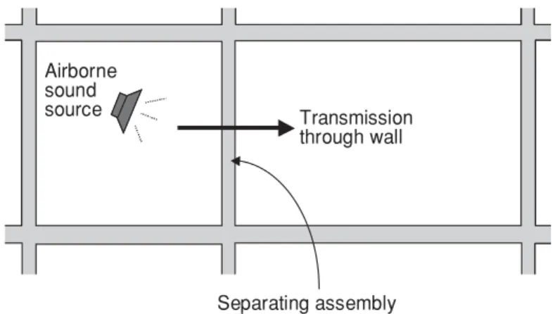
Transmission through wall Airborne sound source Separating assembly
Figure 1.Transmission paths in the traditional approach, which considers only the separating assembly.
Flanking transmission can result from both airborne and impact sources; however, this Update discusses only the transmission of airborne sound. A companion Update will address impact sound.
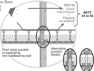
STC 52 ASTC 44 to 45 Alternative junction details Flanking via subfloor
Floor joists parallel to separating non-loadbearing wall
Direct transmission
Flanking and Apparent Sound Transmission Class
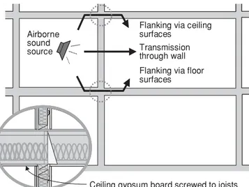
When sound is produced, it causes all surfaces of the space to vibrate. Some of that vibration is transmitted across the floor, ceiling, and adjacent walls, and then through the floor/wall and wall/wall junctions to the corresponding surfaces of the adjacent room, where it is radiated as flanking sound (see Figure 2).
What is heard in the adjacent room is the combination of sound transmitted directly through the separating assembly plus the flanking sound transmitted via all other paths. The rating for this sound transmission via all paths, as experienced by the occupant, is called the Apparent Sound Transmission Class (ASTC). Like STC and FSTC (Field Sound Transmission Class), which are measures of the sound attenua-tion of the separating assembly only, ASTC is a single number
rating defined in ASTM Standard E336.3 The ASTC is usually lower than the STC or FSTC of the separating assembly, and for some combinations of assemblies it is much lower.
2
The prevention of flanking transmission becomes even more important when higher levels of sound insulation are required.
Typical Wood-Frame Construction and Its Effects on Sound
Transmission
The following section illustrates the effects of typical construction details on sound transmission. The discussion concentrates mainly on one set of base assemblies, but other more complex systems show compara-ble trends.
Side-by-Side Units
Floor joists parallel to separating walls
Figure 3 shows the wall with gypsum board screwed directly on to one side of the studs and mounted on resilient metal channels on the other side. Laboratory testing gives this wall assembly an STC of 52. The floor assembly has a bare oriented strandboard (OSB) floor surface, with the gypsum board ceiling mounted on resilient channels (STC 55 in laboratory testing).
Flanking transmission via ceiling surfaces Transmission through wall Airborne sound source Flanking transmission via floor surfaces
Figure 2.Transmission paths in buildings include both direct trans-mission through the separating assembly and flanking transtrans-mission involving adjacent wall and floor assemblies.
Controlling sound (vibrational acoustic energy) starts with choosing a good sepa-rating assembly, but ultimately depends on dealing with the sound energy trans-mitted by all paths.
Retrofitting to reduce flanking is a much more expensive option than addressing the issue in the original design.
Figure 3.Sound transmission between side-by-side units with simple wood-frame wall and floor assemblies
In repeated tests with minor variations of the materials and in the floor/wall junction details, the overall sound insulation observed between the side-by-side rooms was ASTC 44 or 45. Measurements of the wall itself showed that its sound transmis-sion in the complete building system is
very similar to that of the laboratory results (STC 52) for a wall of the same construc-tion. The difference between the wall per-formance and the system perper-formance is due to flanking transmission via the floor assembly, which transmits far more sound than the separating wall assembly.
Floor joists perpendicular to separating walls
For the case shown in Figure 4, the measured ASTC was even lower than the ASTC observed when the joists were parallel to the separat-ing wall (as illustrated in Figure 3). The problem here is not that the separating wall assembly is transmitting more sound than expected—it is performing as designed and built—but that most of the sound energy is able to circumvent the separating wall as structure-borne flanking transmission. Once again, the system ASTC is much lower than the STC of the separating assembly because flanking has not been properly considered in the design.
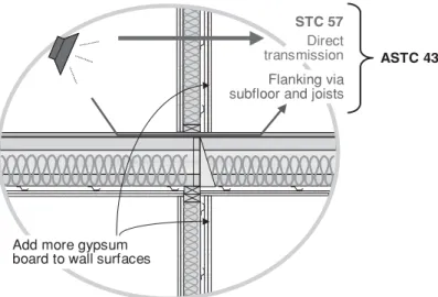
Floor joists perpendicular to separating walls with added layer of gypsum board
The systems illustrated in Figures 3 and 4 are likely to result in noise that most neigh-bouring occupants would find annoying. To remedy this, a builder’s first impulse would likely be to ‘fix’ the separating wall assem-bly by, for example, adding a second layer of gypsum board on the side with resilient channels (see Figure 5). Tables of acoustical ratings for wall assemblies (see Construction Technology Update No. 1) indicate that the added gypsum board should increase the STC for the wall assembly by about 5. In fact, detailed testing showed that the sound transmission directly through the wall was reduced (i.e., the STC increased) as expected, but the system performance was barely affected and only increased to ASTC 43 because the dominant sound transmission path (i.e., structure-borne flanking via the floor) was not dealt with. To address the problem, one must identify all the sound transmission paths and take appropriate measures to eliminate them.
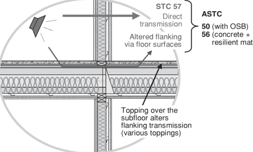
Floor joists perpendicular to separating walls with floor topping added
Since the main problem with the construc-tions shown in Figures 3 to 5 is structure-borne flanking transmission via the floor surface, changing this surface is key to improving the system performance. STC 52 ASTC 42 Floor joists perpendicular to separating loadbearing wall Flanking via subfloor and joists
Direct transmission
Figure 4.Modifying the floor assembly of Figure 3 by reorienting the floor joists to run perpendicular to the separating wall lowers the ASTC for the system.
STC 57
ASTC 43
Add more gypsum board to wall surfaces
Flanking via subfloor and joists
Direct transmission
Figure 5.Adding a layer of gypsum board to the wall assembly shown in Figure 4 has little effect on the ASTC.
Adding a floor topping, such as a layer of concrete or simply a second layer of OSB, can significantly reduce flanking via the floor. Adding floor finishes, such as hard-wood or laminate flooring over a resilient pad, can also reduce flanking transmission (see Figure 6). However, the improvement in the system ASTC rating depends not only on the materials added but also on the floor and junction details of the system to which they are added.
Designing for System Performance
This section outlines the key issues that must be addressed in order to achieve design objectives based on system performance.
Side-by-Side Units
A systems design approach must take into account the transmitted sound energy due to direct transmission through the separating assembly along with that due to significant flanking paths.
Flanking via the floor surface often dom-inates the sound transmission, especially when the floor surface is a single layer of OSB or plywood. When the paths involve the floor, there are several possible approaches:
• Changing the orientation of the floor
joists. In general, floor framing that runs
perpendicular to the separating wall transmits more flanking sound than framing that runs parallel, for both floor surfaces (as shown previously in Figures 3 and 4) and ceilings attached to the bottom of the framing (as discussed below). • Dealing with the flanking transmission
via the floor/wall junction. Reducing
structural connections across the floor/ wall junction reduces flanking; for exam-ple, there is more sound attenuation across the junction for a wall with a double row of studs (because of the gap between the two rows) than for a wall with a single row of studs (see Construction Technology Update No. 16).
• Changing the materials installed on top
of the subfloor. This changes the
trans-mission via the floor surfaces. A heavy floor topping, such as 38-mm concrete, provides much improved sound insula-tion. The addition of other toppings and flooring, including a combination of several different topping layers, can also help achieve reduced flanking.
Unfortunately, making improvements to the floor/floor path is not a complete solu-tion, as other paths may also be significant. For example, once a better floor system has been put in place, sound transmission via other paths will become more obvious. At this point, there is greater benefit from improving other assemblies such as the sep-arating wall, ceilings and sidewalls, which need to be considered as possible paths of sound transmission. The acoustical benefit of specific changes can be weighed and balanced against their cost to optimize the cost/benefit for the complete system.
4
ASTC 50 (with OSB) 56 (concrete +
resilient mat)
Topping over the subfloor alters flanking transmission (various toppings)
Altered flanking via floor surfaces
Direct transmission
STC 57
Figure 6.Adding a floor topping to reduce flanking via the floor/floor path significantly improves the system’s ASTC rating.
For the gypsum board surfaces of walls and ceilings, typical
approaches involve:
• Attaching gypsum board on
resilient channels. This is an
effective way to control flanking via these surfaces—the sound attenuation for the path increases by at least 10 dB. For the sidewall and ceiling paths illustrated in Figures 7 and 8, such an improve-ment can mean that flanking via these paths becomes insignificant. However, to achieve the full bene-fit of this approach, other flanking paths have to be dealt with as well.
• Adding a second layer of
directly attached gypsum board.
This improves flanking control
only slightly—the sound attenuation of the path increases by only 1 or 2 dB.
Figure 7 illustrates the situation typically found in apartment buildings. In single-level apartments, the gypsum board ceiling is normally mounted on resilient channels to enhance the sound insulation from the apartment above. This also reduces flanking transmission between the side-by-side units via the ceiling/ceiling path to an insignificant level.
Flanking via a sidewall transmits less sound than the other paths previously dis-cussed. However, flanking via this path can also limit system performance especially when the separating wall and floor have been improved, as illustrated in Tables 1 and 2 (see page 6).
In applications where sound transmission between storeys within a dwelling unit is not a concern (e.g., row housing), the ceiling is typically screwed directly to the bottom of the joists, as shown in Figure 8. In such cases, the ceiling/ceiling flanking path also becomes significant.
For ceilings, the joists can be parallel or perpendicular to the separating wall. The ceiling path attenuation illustrated in Figure 8 shows the worst-case scenario, with supporting joists of the floor above running perpendicular to the separating wall. Less flanking via the ceiling/ceiling path can be expected when the joists are parallel to the wall. Tables 1 and 2 present the combined effect of all paths for typical variants in construction, capturing the two ceiling attachment cases (Figures 7 and 8) and the effect of specific floor toppings. (See the design guide1for a series of similar tables.)
Flanking via floor surfaces (Ceiling surfaces isolated)
Transmission through wall Airborne
sound source
Ceiling gypsum board on resilient channels Figure 7.Typical sound transmission paths between adjacent one-level apartment units. The sidewalls abutting the separating wall also transmit sound, but resilient channels supporting the gypsum board ceiling block transmission via the ceiling/ceiling path.
Flanking via ceiling surfaces Transmission through wall Airborne sound source
Flanking via floor surfaces
Ceiling gypsum board screwed to joists Figure 8.Typical transmission paths in multi-level
The ASTC in a given building may not match the tabulated values exactly, but the trends apply. In all cases, the system ASTC is lower than the STC rating for the sepa -rating wall—in some cases much lower.
Units One Above the Other
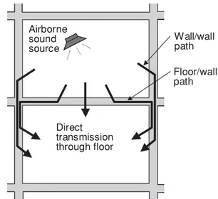
The preceding section shows that for side-by-side units, the ASTC for the whole building system may be far below the STC of the separating wall. The corresponding effects are less dramatic when one unit is above the other, but still warrant design consideration.
The flanking transmission in this case is essentially the same for all the framing variants tested. Transmission via the wall/wall paths shown in Figure 9 is typically weak enough so that it can be ignored. The only significant flanking paths involve the floor surface and the walls in the room below. The effect of joist orientation can usually be ignored in practice because the joists run perpendicular to two walls and parallel to the others.
Because both the direct transmission path and the significant flanking paths involve the floor surface, adding material(s) to the bare floor surface is often the most effective way to improve the sound insula-tion between units. And because the flank-ing transmission via the walls of the room below is comparable to direct transmission through typical ceilings with resilient channels, expensive solutions to improve the ceiling are not likely to provide much improvement in the ASTC, unless they are combined with improvements to the walls as discussed below.
6
Table 1.ASTC for ‘apartment design,’ with joists running perpendicular to separating walls and ceilings suspended on resilient channels, as in Figure 7
Basic wall “Better” wall
Separating wall (STC 52) (STC 57)
Attachment of gypsum Direct or
board on sidewall resilient Direct Resilient
Floor surface Apparent STC (ASTC)
• No topping (basic) 43 43 43 • 19-mm OSB stapled to subfloor 48 50 50 • 25-mm gypsum concrete bonded to subfloor 49 51 52 • 38-mm gypsum concrete + resilient mat on subfloor 51 53 55
Table 2.ASTC for ‘row housing design,’ with joists running perpendicular to the separating walls and ceiling gypsum board fastened directly to the joists, as in Figure 8
Basic wall “Better” wall
Separating wall (STC 52) (STC 57)
Attachment of gypsum Direct or
board on sidewall resilient Direct Resilient
Floor surface Apparent STC (ASTC)
• No topping (basic) 42 43 43 • 19-mm OSB stapled to subfloor 47 48 49 • 25-mm gypsum concrete bonded to subfloor 48 49 50 • 38-mm gypsum concrete + resilient mat on 49 51 52 subfloor Airborne Sound Source Direct transmission through floor Airborne sound source Wall/wall path Floor/wall path
Figure 9.Transmission paths between upper and lower units include both direct transmission through the separating floor and flanking transmis-sion involving the floor and wall assemblies.
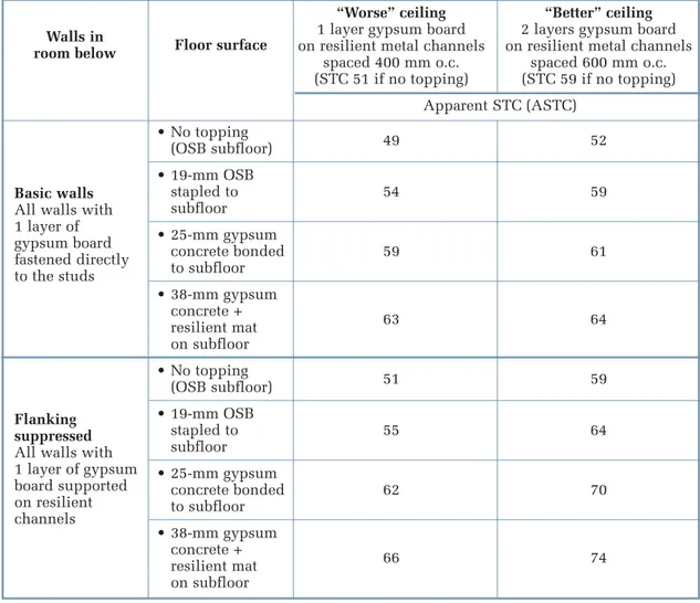
Flanking via the gypsum board surfaces of the walls can also be suppressed as shown in Table 3, which provides an example of sound insulation for a complete building system. The table shows the combined effect of changes to the floor surface, the ceiling and the walls, and allows one to perform a cost/benefit analysis for different design options. This approach follows the same pattern as that used for side-by-side units and is especially helpful when used with lightweight floor surfaces.
The balancing of the sound attenuation for all paths becomes increasingly impor-tant as the desired (design) ASTC increases. In the absence of such balancing, other efforts to achieve high levels of sound insulation can be compromised.
Summary
The experimental characterization of direct and flanking sound transmission paths in wood-frame construction has yielded a set of data that represents the effects of specific design choices. By combining the sound energy transmitted via all paths, it was possible to obtain estimates of the overall system performance—that is, the ASTC— for different combinations of construction details. These details have been combined in a design guide that allows designers to select cost-effective constructions with the desired ASTC.
Table 3.ASTC between units (one unit above the other) for selected variations of the floor/ceiling assembly and the wall surfaces in the room below
“Worse” ceiling “Better” ceiling
1 layer gypsum board 2 layers gypsum board on resilient metal channels on resilient metal channels
spaced 400 mm o.c. spaced 600 mm o.c. (STC 51 if no topping) (STC 59 if no topping) Apparent STC (ASTC) • No topping (OSB subfloor) 49 52 • 19-mm OSB stapled to 54 59 subfloor • 25-mm gypsum concrete bonded 59 61 to subfloor • 38-mm gypsum concrete + resilient mat 63 64 on subfloor • No topping (OSB subfloor) 51 59 • 19-mm OSB stapled to 55 64 subfloor • 25-mm gypsum concrete bonded 62 70 to subfloor • 38-mm gypsum concrete + resilient mat 66 74 on subfloor Basic walls
All walls with 1 layer of gypsum board fastened directly to the studs
Walls in
room below Floor surface
Flanking suppressed All walls with 1 layer of gypsum board supported on resilient channels
“Construction Technology Updates” is a series of technical articles containing practical information distilled from recent construction research.
For more information, contact Institute for Research in Construction, National Research Council of Canada, Ottawa K1A 0R6
Telephone: (613) 993-2607; Facsimile: (613) 952-7673; Internet: http://irc.nrc-cnrc.gc.ca © 2008
National Research Council of Canada March 2008
ISSN 1206-1220
Notes
1. More detail is available in the Guide for Sound Insulation in Wood Frame
Construction (RR-219, Institute for Research in Construction, National Research Council Canada, 2006) by D. Quirt, T.R.T. Nightingale and F. King.
This document concerns wood-frame con-struction and is based on the results of extensive testing for both airborne and impact sources. The guide is available at http://irc.nrc-cnrc.gc.ca/pubs/rr/rr219/. 2. See 2005 National Building Code of
Canada.
3. See ASTM International E 336-2005, Standard Test Method for Measurement of Airborne Sound Attenuation between Rooms in Buildings.
Dr. J.D. Quirt is a senior research officer in the
Indoor Environment program at the National Research Council Institute for Research in Construction.
Dr. T.R.T. Nightingale is a research officer in the
same program.
The project was sponsored by a group of industry partners, including Canada Mortgage and Housing Corporation (CMHC), Forintek Canada Corp., the National Research Council Institute for Research in Construction (NRC-IRC), Owens Corning, USG and TrusJoist. The industry partners not only con-tributed to the funding, but also partici-pated in the steering committee that directed the work.