Publisher’s version / Version de l'éditeur:
Journal of Materials, 20, January 1, pp. 29-36, 2008-01-01
READ THESE TERMS AND CONDITIONS CAREFULLY BEFORE USING THIS WEBSITE.
https://nrc-publications.canada.ca/eng/copyright
Vous avez des questions? Nous pouvons vous aider. Pour communiquer directement avec un auteur, consultez la première page de la revue dans laquelle son article a été publié afin de trouver ses coordonnées. Si vous n’arrivez pas à les repérer, communiquez avec nous à [email protected].
Questions? Contact the NRC Publications Archive team at
[email protected]. If you wish to email the authors directly, please see the first page of the publication for their contact information.
NRC Publications Archive
Archives des publications du CNRC
This publication could be one of several versions: author’s original, accepted manuscript or the publisher’s version. / La version de cette publication peut être l’une des suivantes : la version prépublication de l’auteur, la version acceptée du manuscrit ou la version de l’éditeur.
Access and use of this website and the material on it are subject to the Terms and Conditions set forth at
Corrosion inhibiting systems for durable concrete bridges - Part 2:
Accelerated laboratory investigation
Qian, S. Y.; Cusson, D.; Chagnon, N.
https://publications-cnrc.canada.ca/fra/droits
L’accès à ce site Web et l’utilisation de son contenu sont assujettis aux conditions présentées dans le site LISEZ CES CONDITIONS ATTENTIVEMENT AVANT D’UTILISER CE SITE WEB.
NRC Publications Record / Notice d'Archives des publications de CNRC: https://nrc-publications.canada.ca/eng/view/object/?id=d07a5469-1bee-4b34-80e0-e76c4cd0cf27 https://publications-cnrc.canada.ca/fra/voir/objet/?id=d07a5469-1bee-4b34-80e0-e76c4cd0cf27
http://irc.nrc-cnrc.gc.ca
C o r r o s i o n i n h i b i t i n g s y s t e m s f o r d u r a b l e
c o n c r e t e b r i d g e s – P a r t 2 : A c c e l e r a t e d
l a b o r a t o r y i n v e s t i g a t i o n
N R C C - 4 8 1 3 6
Q i a n , S . Y . ; C u s s o n , D . ; C h a g n o n , N .
A version of this document is published in / Une version de ce document se trouve dans: Journal of Materials, v. 20, no. 1, Jan. 2008, pp. 29-36
The material in this document is covered by the provisions of the Copyright Act, by Canadian laws, policies, regulations and international agreements. Such provisions serve to identify the information source and, in specific instances, to prohibit reproduction of materials without
written permission. For more information visit http://laws.justice.gc.ca/en/showtdm/cs/C-42
Les renseignements dans ce document sont protégés par la Loi sur le droit d'auteur, par les lois, les politiques et les règlements du Canada et des accords internationaux. Ces dispositions permettent d'identifier la source de l'information et, dans certains cas, d'interdire la copie de
Corrosion-Inhibiting Systems for Durable Concrete Bridges –
Part 2: Accelerated Laboratory Investigation
Shiyuan Qian
1, Daniel Cusson
2, Nathalie Chagnon
3, and Bruce Baldock
4Abstract: Nine commercially available corrosion-inhibiting systems for use in concrete structures exposed to corrosive environments were evaluated on bridge barrier walls and in electrochemical cells. The results of this study are presented in two companion papers reporting on a five-year field evaluation and an accelerated laboratory investigation. The later, presented in this paper, included the assessment of the effect of the corrosion inhibitors on the oxidation and reduction reactions by the cyclic voltammetry method, and their effectiveness in delaying or reducing corrosion by measurements of chloride thresholds and corrosion rates. The results indicated that the inorganic admixture and some organic admixtures performed very well in the saturated calcium hydroxide solution (pH of 12.6); however, their performance improvement over the control was not observed in a simulated concrete pore solution (pH of 13.5). Although tests in simulated concrete pore solutions cannot adequately simulate all the complex conditions usually found in the field, they were very useful to rapidly identify the effects of the corrosion inhibitors on the corrosion reactions, and to provide supporting information to the corresponding field evaluation.
CE Database subject headings: corrosion, reinforcement, concrete,corrosion inhibitors, pore solutions
1
Senior Research Officer, National Research Council Canada, 1200 Montreal Rd., Ottawa, Ontario, Canada, K1A 0R6, Email: [email protected].
2
Research Officer, National Research Council Canada, 1200 Montreal Rd., Ottawa, Ontario, Canada, K1A 0R6, Tel.: (613) 998-7361, Fax.: (613) 952-8102, Email: [email protected].
3
Technical Officer, National Research Council Canada, 1200 Montreal Rd., Ottawa, Ontario, Canada, K1A 0R6, Email: [email protected].
4
Technical Officer, National Research Council Canada, 1200 Montreal Rd., Ottawa, Ontario, Canada, K1A 0R6, Email: [email protected].
INTRODUCTION
Corrosion of steel reinforcement in concrete structures is a serious problem worldwide resulting in a loss of durability requiring costly maintenance. Corrosion inhibitors are considered as one of the most cost-effective solutions in addressing this problem. They have been increasingly used in the construction of new structures and the rehabilitation of existing structures during the last twenty years. Earlier studies on corrosion inhibitors focused mainly on sodium benzoate (Lewis et al. 1956; Treadaway and Russel 1968), on various nitrites (sodium, potassium and barium) and on chromates/dichromates (Griffin 1975; Berke 1989) as concrete admixtures for the inhibition of corrosion in reinforced concrete structures. None of these corrosion inhibitors performed satisfactorily and many of them led to detrimental effects on the strength development of concrete. A study of the effectiveness of calcium and sodium nitrites by
Rosenberg et al. (1977) revealed the benefits of these corrosion inhibitors in concrete. Since then, calcium nitrite has become commercially available and has been studied and used extensively in reinforced concrete structures exposed to de-icing salts (Berke and Weil 1992; El-Jazairi and Berke 1990; Hope and Ip 1989). During the 1990’s, a number of organic inhibitors were developed and commercialized, such as amines, alkanolamines, their salts with organic and inorganic acids (Maeder 1994), and emulsified mixtures of esters, alcohols and amines (Nmai et al. 1992).
Most of the corrosion-inhibiting materials on the market claim inhibitory mechanisms based on either laboratory experiments or periodic field observations. Thorough investigations combining the results of laboratory testing and long-term field performance evaluation to understand the factors governing the in-service corrosion-inhibiting effectiveness of these materials are limited in the literature.
This paper is the second of two companion papers presenting an evaluation of corrosion-inhibiting systems for use on concrete bridges. In the first paper, the focus was on evaluation of the field
performance of nine commercial corrosion-inhibiting systems installed on a reconstructed concrete barrier wall at the Vachon Bridge, located north of Montreal, Canada. Field corrosion measurements, such as half-cell potential, corrosion rate, concrete resistivity were performed annually for five years. In this paper, accelerated laboratory corrosion tests in simulated concrete pore solutions were carried out to provide support to the field study with additional information on the corrosion-inhibiting systems.
EXPERIMENTAL PROCEDURES
Corrosion-Inhibiting Systems and Concrete Specimens
The corrosion-inhibiting systems evaluated in this study contain either concrete admixtures, rebar coatings, concrete coatings/sealers or a combination of the above. A generic description of the corrosion-inhibiting systems is presented in Table 1, in which the proprietary systems were identified with arbitrary labels from A to H. Note that the commercial names of these systems are not identified in this paper in order to maintain confidentiality as requested by the product suppliers.
In the field study, eight 35-m long sections of a bridge barrier wall were built using a standard concrete (see the Part 1 companion paper) and conventional carbon-steel reinforcement, each including a different corrosion-inhibiting system provided and installed by its manufacturer. Two other test sections were built using the same concrete but with no corrosion inhibitors: one section had carbon-steel reinforcement (identified as the Control Section), and the other section had epoxy-coated steel reinforcement (identified as the Epoxy Section).
In the laboratory study, the corrosion-inhibiting admixtures included in some systems (namely Systems B, C, E, F and H) were tested separately from the cementitious coatings included in the other systems
(namely Systems A, D and G). The cyclic voltammetry method was used to determine the effect of the corrosion-inhibiting admixtures on the oxidation and reduction reactions. The effectiveness of the admixtures and the coatings was evaluated by conducting chloride (Cl) threshold tests and corrosion rate
measurements. The concentrations of the corrosion-inhibiting admixtures used in the electrolytes were: 1.1%, 35%, 4.2%, 1.2% and 7.8% for Admixtures B, C, E, F and H, respectively (as suggested by the manufacturers for the laboratory experiments).
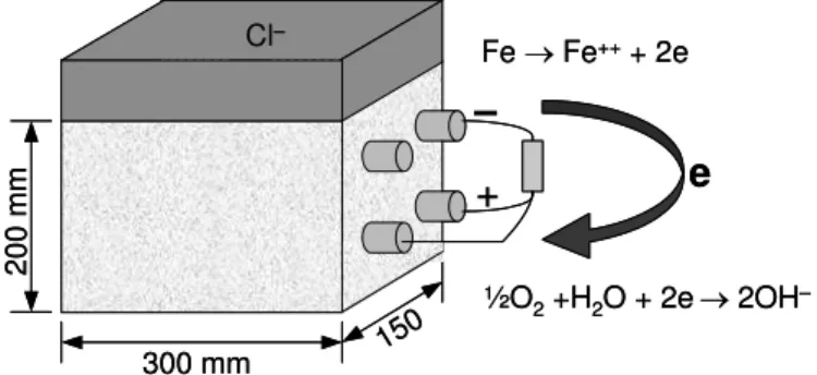
For each corrosion-inhibiting system installed on the bridge in 1996, companion reinforced concrete prisms were field-cast at the same time for laboratory testing. The concrete had a water-cement ratio (w/c) of 0.36 and the mix design can be found in the companion paper. As shown in Figure 1, the prisms were of a size of 200 x 300 x 150 mm3 and included two layers of 15-mm rebars with their ends epoxy-coated
in order to expose only 250 mm of steel to the concrete. The concrete cover thickness of the prisms was 40 mm. One of the top reinforcing bars was connected through a 100-ohm resistor to the bottom bars, while the other top bar was kept disconnected. This configuration was used to simulate a field condition where the first layer of reinforcement is contaminated by chlorides (acting as an anode), and the second layer of reinforcement is in a passive condition (acting as a cathode). After 28 days of wet curing in the laboratory, a dam was installed on the top of each prism, and the solution was cycled wet/dry biweekly for five years to let chloride and moisture diffuse into the concrete. Two prisms per corrosion-inhibiting system were ponded with 3.5% sodium chloride (NaCl) solution during the wet period, and kept in a room at a 50% relative humidity and a temperature of 25°C. In 2001, the wet/dry cycling test condition was changed to continuous ponding using a 3.5% NaCl solution.
Steel Electrodes and Electrolytes
The working electrodes used for the laboratory experiments with electrochemical cells were machined from 10-mm reinforcing carbon steel bars to a size of 8 mm in diameter and 10 mm in length. Each steel electrode was soldered to a 10-gauge copper wire, which was isolated from the solution by a glass tube. The electrodes were then embedded in epoxy to cover all surfaces, except one end with an exposed area of 50 mm2. Before testing, the steel electrodes were polished with a #600 silicon carbide paper and immersed
different corrosion-inhibiting materials provided by the manufacturers, and normal Type 10 cement paste referred to as the control. All the coatings on the steel electrodes had the same thickness of 1 mm.
One difficulty in testing steel corrosion in electrolytes is to use a solution that adequately represents the concrete pore environment. Saturated calcium hydroxide [Ca(OH)2] with a pH of 12.6 has been often used
in the past to simulate the pore solution in concrete. However, Longuet et al. (1973) and Diamond (1975) analyzed the pore solution of hardened cement paste and found that it contains sodium hydroxide and potassium hydroxide, and a small amount of calcium hydroxide, resulting in a pH above 13. This finding was later confirmed by Page and Vennesland (1982) and Andrade (1986).
Since alkalinity of the concrete pore solution has an important influence on steel corrosion (Goni and Andrade 1990; Dehwah et al. 2002), two types of electrolytes that are representative of two typical field conditions were used in this laboratory study: a saturated Ca(OH)2 solution of a pH of 12.6, and a
simulated concrete pore solution [0.002 M Ca(OH)2 + 0.45 M NaOH + 0.26 M KOH] of a pH of 13.5
(Mammoliti et al. 1999; Kitowski and Wheat 1997; Ramirez et al. 1990). The corrosion-inhibiting admixtures were added to the electrochemical cells in the concentrations suggested by the manufacturers one week after the electrode samples were immersed in the solution. Afterward, NaCl was added to the cells, and its concentration was increased weekly by 0.2% or 0.5% increments (depending on the samples) until significant corrosion developed on the electrode in order to determine the chloride-induced corrosion threshold of each corrosion inhibitor. The electrochemical cells were kept closed to prevent a decrease in the solution pH, which never reduced more than 0.3 from the desired value.
Electrochemical Measurements
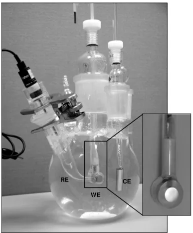
The electrochemical measurements included half-cell potential, linear polarization, cyclic voltammetry, and AC impedance, which were carried out using a computer-controlled electrochemical interface coupled with a frequency response analyzer. These measurements were performed in electrochemical cells
composed of three electrodes: a working electrode (steel sample), a counter electrode (platinum foil or mesh) and a saturated calomel reference electrode (SCE), as illustrated in Figure 2. Such glass cells are widely used for experiments using high pH solutions (Hope et al. 2001; Ramirez et al. 1990). A Luggin capillary was used to reduce the IR drop between the SCE and the working electrode. The value of the polarization resistance was determined from the average of three measurements and based on the slope of the potential-current relation near the open circuit potential . The potential range of the cyclic voltammetry experiments was typically set at –1.17 to 0.63 V in order to avoid excessively-high reduction or oxidation reactions that could cause a change in the surface condition of the steel electrode. The measurements were conducted at a scan rate of 1 mV/s to allow the reaction peaks to appear clearly on the cyclic
voltammograms. Attempts to correct the IR-drop between the Luggin capillary of the reference electrode and the working electrode were made using the AC impedance method. However, the effect of the IR-drop on these measurements was found to be negligible because of the high electrical conductivity of the electrolyte and the low current measured.
Macrocell current, polarization resistance and corrosion potential were also measured on the field-cast reinforced concrete prisms. The macrocell current was measured with a high input impedance voltmeter by reading the potential drop across the 100-ohm resistor between the top and bottom rebars. Half-cell potentials were also measured with a high impedance voltmeter during the wet cycle by placing a saturated calomel reference electrode on the concrete over the middle point of the electrically isolated rebar. Polarization resistance was determined by the linear polarization method, using a large stainless steel counter electrode place on the concrete surface over the rebar to provide uniform current distribution.
RESULT ANALYSIS AND DISCUSSION
Commercial corrosion-inhibiting systems are often blends of several compounds, and can involve more than one corrosion-inhibiting mechanism, which are often difficult to identify. They can inhibit corrosion in different ways, by: i) reducing the chloride ingress in concrete; ii) increasing the corrosion initiation
threshold; iii) reducing the corrosion rate after corrosion initiation; or iv) a combination of the above. Table 2 provides a brief description of the mechanisms of the admixtures reported in the product data sheets and from the literature (Elsener 2001).
Cyclic Voltammograms without Corrosion-Inhibiting Admixtures
Cyclic voltammograms measured on the reinforcing steel in the presence of corrosion-inhibiting
admixtures can provide useful information on the reactions involved in the anodic oxidation and cathodic reduction. This was achieved by scanning the applied electrode potential from the open circuit potential towards the anodic region, followed by scanning in the reverse cathodic direction and so on. The
electrochemical processes occurring on the steel surface correspond to various peaks in the voltammogram and are briefly described here to aid in understanding the basis behind the application of the method.
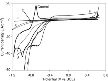
Figure 3 (thin curve) shows a cyclic voltammogram measured on a carbon steel electrode in a saturated Ca(OH)2 solution in an electrochemical cell sealed with a special bubbler to purge oxygen. The plateau
prior to Peak A1 (from –1.1 V to –0.8 V) is attributed to the formation of Fe(OH)2 and/or FeO. In this
study, no clear peaks were observed within this potential range; however, in other studies (Andrade et al. 2001), two separate peaks could be observed. The formation of these peaks might depend on the exact solution composition used and/or the thickness of the passive film formed on the steel electrode. Peak A1
at –0.7 V is assigned to ferrous-ferric (Fe(OH)2/FeOOH) transformations (Hinatsu et al. 1988). The
potential range that is more positive than this peak (e.g. flat current region) corresponds to the passive range, in which the current is very small but can still maintain the passive protective film on the steel surface. When the potential becomes higher than +0.63 V, the current increases suddenly and oxygen evolution becomes the predominant reaction. The plateau and Peak C1 (at –0.98 V) in the cathodic scan
(from –0.6 V to –1.1 V) are the counterpart of the anodic reactions. At more negative values, near –1.17 V, the negative current increases rapidly and hydrogen evolution becomes the predominant reaction. When the steel electrode was cycled in a cell containing oxygen (thick curve in Figure 3), both the
cathodic and anodic currents became more negative for potentials more negative than –0.45V due to an increase in the cathodic current of the oxygen reduction reaction. This voltammogram is referred to as the control (no corrosion-inhibiting admixture) in this study.
Cyclic Voltammograms with Corrosion-Inhibiting Admixtures
The effect of the corrosion-inhibiting admixtures on the oxidation and reduction reactions were studied using the above procedure. Cyclic voltammetry experiments were carried out on carbon steel electrodes in a saturated Ca(OH)2 solution with the addition of the corrosion-inhibiting admixtures, for which the
results are presented in Figure 4. In the presence of Admixtures C, E and F, the cyclic voltammograms show that the reaction peaks on both anodic and cathodic scans disappeared. This may be due to the adsorption of their organic compounds on the steel surface, which formed a thin film acting as a physical barrier against corrosion (Milsik et al. 1989; Brundle et al. 1996). Although this experiment was carried out in cells containing oxygen, the current for the oxygen reduction was also significantly reduced. The chemical adsorption on the steel was stronger in the presence of Admixture E than Admixtures C and F, since the current on the cyclic voltammogram was suppressed to a very small value.
The cyclic voltammogram in the presence of Admixture H shows a different behavior. Both anodic and cathodic reaction currents increased because the admixture might have enhanced the passive film on the steel electrode through the oxidation of Fe2+ ions. The increase in the anodic current was possibly due to
this oxidation reaction, however, the increase in the cathodic current was mainly the counterpart of the anodic reaction.
In the presence of Admixture B, the cyclic voltammogram shows a current reduction in the anodic scan. The peaks for the ferrous-ferric transformations and the counter reaction are not as pronounced as those of the control. The anodic current was observed to decrease with an increase in the number of cycles
adsorb on the steel surface and form an organic film, possibly leading to the reduction of the anodic and cathodic currents. However, the organic film formation was slower and the adsorption of the organic compounds was weaker with Admixture B than with Admixtures C, E and F.
Cyclic voltammetry tests were also conducted with a simulated concrete pore solution of a pH of 13.5 in the presence of the same admixtures. The obtained voltammograms were somewhat similar to those obtained for the saturated Ca(OH)2 solution, with anodic and cathodic current reductions in the presence
of Admixtures C, E, and F, when compared to the control. However, the current reductions obtained in this simulated concrete pore solution were not as significant as those obtained in the saturated Ca(OH)2
solution, indicating that the adsorption of these organic compounds was probably not as strong as in the later solution. The cyclic voltammograms in the presence of Admixtures B and H showed only marginal current increases in the anodic scans. These results indicate that the effectiveness of organic admixtures in forming a protective film, and the ability of the inorganic admixture to enhance the passive film formation on the steel surface, depend largely on the solution pH (Mammoliti et al. 1999).
Effect of Admixtures on Chloride Threshold and Corrosion Rate
The corrosion rate (icorr) changes proportionally with the reciprocal of polarization resistance (RP) as
shown in the following equation:
P E corr
R
K
E
i
K
i
corr1
=
⎟
⎠
⎞
⎜
⎝
⎛
Δ
Δ
=
(1)where Δi and ΔE are the changes in current and potential, respectively, over a small range of values near the corrosion potential (Ecorr); and K is a constant related to the Tafel slopes of anodic and cathodic
polarizations. When the steel surface is passivated, the Tafel slopes are often difficult to determine. The value of 1/RP was therefore used to compare the corrosion rates of the carbon steel electrodes in the
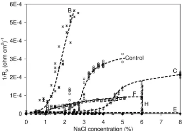
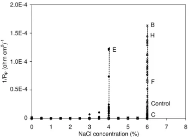
The development of 1/RP for an increased chloride concentration in the saturated Ca(OH)2 solution
(pH=12.6) are plotted in Figure 5 for the various admixtures. In the presence of Admixture B, 1/RP started
to rise at around 0.7% NaCl and then increased sharply as more NaCl was added. In the presence of Admixture F, 1/RP started to rise at the low NaCl concentration of 1.1% but increased at a slow rate due
probably to the adsorption of organic compounds on the steel electrode. For the control and Admixture C,
1/RP rose at around 2% and 4% NaCl, respectively, and increased quite rapidly thereafter. With inorganic
Admixture H, 1/RP remained small until the 6% NaCl concentration was reached, and then increased
suddenly. In the case of Admixture E, 1/RP remained very low until 8% NaCl was reached, without
indication of further increases because of strong adsorption of organic compounds on the steel electrode. With these last two admixtures, the chloride thresholds were increased significantly by about 4% and 6% NaCl compared to the control, respectively.
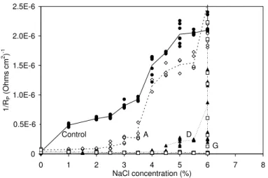
The development of 1/RP for an increased chloride concentration was also tested in a simulated concrete
pore solution (pH=13.5) as shown in Figure 6. The value of 1/RP started to rise at a 6% NaCl
concentration for the control and most admixtures. Admixture E, which obtained the highest chloride threshold (8% NaCl) in the previous solution (pH=12.6), obtained the lowest threshold of 4% NaCl in this solution (pH=13.5). This can be explained by the fact that steel can tolerate higher amounts of chlorides in higher pH solutions, even without the addition of a corrosion inhibitor, as the initiation of steel corrosion depends largely on the chloride/hydroxide ratio (Hausmann 1967; Hussain et al. 1996). Tests carried out by Mammoliti et al. (1999) in a simulated concrete pore solution of a pH ≈ 13.3 also showed that organic and inorganic corrosion inhibitors were ineffective in increasing the chloride threshold in high pH.
Effect of Rebar Coatings on Chloride Threshold and Corrosion Rate
Some corrosion-inhibiting systems investigated in the corresponding field study included cementitious coatings. The effectiveness of the coatings in delaying rebar corrosion was tested in a saturated Ca(OH)2
solution (pH = 12.6) by measuring the corrosion potential and 1/RP, and by conducting visual inspections.
In these tests, a proprietary rebar coating was considered effective if the corrosion rate (or 1/RP) was lower
and the chloride threshold higher than those of a control type-10 cement coating.
Figures 7 and 8 show the half-cell potential and 1/RP values, respectively, measured on the steel electrodes
with Coatings A, D and G and the control coating. A drastic potential drop from approximately –0.2 V to –0.6 V and a sudden increase in 1/RP at approximately 1.0% NaCl were observed for the control coating.
As more sodium chloride was added to the solution, the half-cell potential almost remained at this level but 1/RP continued to increase significantly, indicating that the chlorides reached the surface of the steel
and corrosion initiated.
For Coatings A and D, the onset of corrosion in the sample was observed at 3.5 % and 4.5% NaCl, respectively, by both half-cell potential and 1/RP measurements. For Coating G, corrosion initiated on the
sample at 6.0% NaCl. The corrosion on these samples was confirmed by observations of corrosion products on the steel electrodes. The three proprietary coatings, especially Coatings D and G, were found more effective than the control cementitious coating in delaying initiation of corrosion of reinforcing steel when tested in the saturated Ca(OH)2 solution.
Corrosion of Steel Bars in Concrete Prisms
As mentioned earlier, these prisms were made of a 0.36 w/c concrete (see companion paper) and were protected with the full corrosion-inhibiting systems as listed in Table 1. First, macrocell currents were measured on the concrete prisms. It was found that the measured potential drops across the 100-ohm resistor in all concrete prisms (except the control prisms) remained smaller than 0.1 mV, corresponding to a negligible current (i.e. smaller than 1 μA or a current density lower than 0.008 μA/cm2
). This small macrocell current is an indication that the top and bottom rebars of most concrete prisms have similar good surface conditions. The potential drops measured on the control prisms, however, were slightly
larger than the values measured on the other prisms, indicating possible initiation of corrosion on the top rebars of the control prisms.
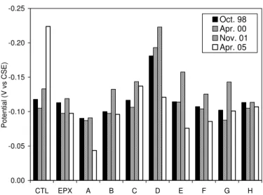
Average half-cell potentials, recorded in 1998, 2000, 2001 and 2005 for prisms ponded with salt water, are shown in Figure 9. The half-cell potential values (measured with SCE) shown in this figure were
converted relative to copper sulfate reference electrode (CSE) bysubtracting 74 mV from the original readings for direct comparison with the ASTM C678 guidelines. The results show that the half-cell potentials of all concrete prisms measured in 2005 were more positive than –200 mV vs. CSE (except the controls), which is an indication of low probability of corrosion according to ASTM C876. The control prisms had a significant increase in negative potential in 2005, indicating that corrosion possibly initiated on the top rebars. These results are consistent with the measurements of macrocell current discussed previously.
The 1/Rp values obtained from linear polarization measurements on the concrete prisms are shown in Figure 10. As expected, corrosion currents were very low in most prisms indicating that rebar corrosion has not initiated. The 1/Rp values measured on the control prisms were higher in 2005 than on the other prisms, which are consistent with the half-cell potential readings. More time is required for the
development of significant corrosion in these reinforced concrete prisms in order to clearly distinguish the effectiveness of the corrosion-inhibiting systems from the control concrete. It should be noted that these prisms were made of a low permeability concrete, were free of cracks, and were tested in a relative dry condition, as only the top surface was ponded with salt water. Once the corrosion rates of the embedded reinforcing bars will be considered high enough, the prisms will be opened for visual examination of the corrosion damage.
Effect of Test Conditions on Corrosion Inhibitor Effectiveness
The long period of time usually required for evaluating the effectiveness of corrosion-inhibiting systems in reinforced concrete structures has led to the development of accelerated corrosion evaluation techniques, mainly in electrochemical cells using simulated concrete pore solutions. Many studies, however, showed that the differences in the physical and chemical properties between the simulated concrete pore solution and the actual concrete might affect differently the chemical reactions involved in the corrosion of reinforcement and the corrosion-inhibiting process (Hausmann 1967; Treadaway and Russel 1968; Gouda and Halaka 1970; Andrade et al. 2001).
Saturated Ca(OH)2 solutions (pH of 12.6) provide a good simulation of old/carbonated concretes, or new
concretes containing about 10-30% silica fume, which is widely used in high-performance concrete. As found in the present study, many corrosion-inhibiting materials tested in this solution provided better performance than the control. For instance, Admixtures C, E and H and Coatings A, D, and G provided good performance by increasing the chloride threshold and reducing the corrosion rate of the reinforcing bars when compared to the controls.
Simulated concrete pore solutions (pH of 13.5) provide a close simulation of new normal Portland cement concrete. This study indicated that none of the inhibitors tested in this solution were able to outperform the control. Moreover, Admixture E (which provided the best performance of the group in the lower pH solution) performed worse than the control and the other admixtures.
In the field study, reported in the companion paper, the performance improvements of the corrosion-inhibiting systems over the control system were not as marked as those observed in the laboratory study conducted in the electrochemical cells with the lower pH solution. The same comparison can be made regarding the tests on the field-cast reinforced concrete prisms. The high alkalinity of the relatively new
concrete used in the barrier wall (which had no silica fume) and the thick concrete cover (75 mm) are factors explaining the delay in the initiation of corrosion in concrete.
However, on specific test areas of the barrier wall, where the concrete cover thickness had been substantially reduced (down to 13 mm), System H consistently provided better performance than the control and the other corrosion-inhibiting systems in delaying corrosion of the embedded rebars. This conclusion is in good agreement with the laboratory results, in which Admixture H was consistently found to perform satisfactorily in delaying initiation of corrosion.
It should be pointed out that the selection of the appropriate corrosion-inhibiting systems for field use should be based primarily on the results obtained from long-term field studies on concrete structures, which often include complex combinations of the following factors: concrete cracking, stress in the reinforcement, freeze-thaw and wet-dry cycles, periodic spraying of de-icing salts, carbonation, and the presence of sealers and coatings in the system, which can hardly be reproduced simultaneously in the laboratory. However simulated concrete pore solutions were very useful to rapidly identify the individual effects of the corrosion inhibitors on the corrosion reactions, and to provide supporting information to the corresponding field evaluation.
SUMMARY AND CONCLUSIONS
This accelerated laboratory investigation included the assessment of the (i) effect of corrosion-inhibiting admixtures on the oxidation and reduction reactions by the cyclic voltammetry method; (ii) the
effectiveness of these admixtures and cementitious coatings in delaying or reducing steel corrosion by testing for chloride thresholds and corrosion rates; and (iii) the laboratory performance of corrosion-inhibiting systems in reinforced concrete prisms. From the results of this investigation, the following conclusions were drawn:
• Simulated concrete pore solutions were very useful to rapidly identify the individual effects of the inhibitors on the corrosion reactions, and to provide supporting information to the corresponding field evaluation.
• In the saturated Ca(OH)2 solution (pH of 12.6), Admixtures E, H and C obtained chloride thresholds
higher than the control. Admixtures B and F obtained low chloride thresholds, however, Admixture F was able to keep the corrosion rate low with further increases in the chloride concentration.
• In the simulated concrete pore solution (pH of 13.5), the effectiveness of the corrosion-inhibiting admixtures in increasing the chloride threshold of steel was not observed. Admixture E obtained a lower chloride threshold than the control, indicating that the performance of corrosion-inhibiting admixtures depends on the solution pH surrounding the steel/concrete interface.
• The cyclic voltammograms showed that the anodic and cathodic currents reduced significantly in the presence of organic inhibitors (Admixtures E, C, and F). This may be due to the adsorption of organic compounds on the steel electrode. With the inorganic inhibitor (Admixture H), these currents were increased to possibly enhance the passive film formation on the steel electrode.
• Coatings A, D, and G provided good performance in the saturated Ca(OH)2 solution by increasing the
chloride threshold and reducing the corrosion rate of the reinforcing bars when compared to the control coating.
• Corrosion measurements on the reinforced concrete prisms showed that the rebars in most prisms were in a passive condition, probably due to the absence of cracks, low concrete permeability and dryness of the concrete prisms. Only the control prisms showed some signs of corrosion initiation of the reinforcing bars. More time is required to compare the performance of the different corrosion-inhibiting systems tested on these concrete prisms.
ACKNOWLEDGEMENTS
The authors wish to thank their partners for their contributions to the project, in particular: the Ministry of Transportation of Quebec, Axim Concrete Technology, Caruba Holdings, Euclid Admixture Canada, Israel Richler Trading, Master Builders Technologies, Sika Canada, W.R. Grace & Co, and the Regional Municipality of Peel. The authors would also like to thank Mr. Glendon Pye and Mr. Gordon Chan for their valuable technical assistance.
NOTATION
The following symbols are used in the paper:
Ecorr = corrosion potential
icorr = corrosion current
Κ = constant related to the Tafel slopes of anodic and cathodic polarizations
RP = polarization resistance
ΔE = change in corrosion potential
Δi = change in corrosion current
REFERENCES
Andrade, C., Alonso, C. and González, J. (1986). "Some laboratory experiments on the inhibitor effect of sodium nitrite on reinforcement corrosion," Cement Concrete and Aggregates, CCAGDP, Vol. 8, No.2, 110-116.
Andrade, C., Keddam, M., Nóvoa, X.R., Pérez, M.C., Rangel, C.M. and Takenouti, H. (2001).
"Electrochemical behaviour of steel rebars in concrete: influence of environmental factors and cement chemistry," Electrochimica Acta, Vol. 46, 3905-3912.
Berke, N.S. (1989). "Corrosion inhibitors in concrete," Corrosion 89, Paper 445, NACE, Houston, Texas, 1-10.
Berke, N.S. and Weil, T.G. (1992). "World-wide review of corrosion inhibitors in concrete," Advances in
Concrete Technology, CANMET, 899-924.
Brundle, C.R., Grunze, M., Mäder, U. and Blank, N. (1996). "Detection and characterization of dimethylethanolamine-based corrosion inhibitors at steel surfaces, Part 1: The use of XPS and ToF-SIMS," Surface and Interface Analysis, Vol. 24, No. 9, 549-563.
Dehwah, H.A.F., Maslehuddin, M. and Austin, S.A. (2002). "Effect of cement alkalinity on pore solution chemistry and chloride-induced reinforcement corrosion," ACI Materials Journal, Vol. 99, No. 3, 227-233.
Diamond, S. (1975). "Long-term status of calcium hydroxide saturation of pore solutions in hardened cements," Cement and Concrete Research, Vol. 5, 607-616.
El-Jazairi, B. and Berke, N.S. (1990). "The use of calcium nitrite as a corrosion-inhibiting admixture to steel reinforcement in concrete," Corrosion of Reinforcement in Concrete, Elsevier Science Publishers Ltd., Wishaw, Warwickshine, UK, 571-585.
Elsener, B. (2001). "Corrosion inhibitors for steel in concrete," State of the art report, European Federation of Corrosion Publications, Number 35, Maney Publishing, 1-63.
Goni, S. and Andrade, C. (1990). "Synthetic concrete pore solution chemistry and rebar corrosion rate in the presence of chlorides," Cement and Concrete Research, Vol. 20, 525-539.
Griffin, D.F. (1975). "Corrosion inhibitors for reinforced concrete," Corrosion of Metals in Concrete, ACI SP-49, American Concrete Institute, 95-102.
Hausmann, D.A. (1967). "Steel corrosion in concrete: How does it occur?" Materials Protection, Vol. 6, November, 19-23.
Hinatsu, J.T., Graydon, W.F. and Foulkes F.R. (1988). "Voltammetric behaviour of iron in cement, Part 1: Development of a standard procedure for measuring voltammograms," Journal of Applied
Hope, B., Hansson C., Trépanier S. Mammoliti L. (2001). "Corrosion inhibitors for concrete," Technical
Report, Materials engineering and Research Office, Concrete Section, MTO, 1-49.
Hope, B.B. and Ip, A. K. C. (1989). "Corrosion inhibitors for use in concrete," ACI Materials Journal, Vol. 86, No. 6, 602-608.
Hussain, S. Al-Gahtani, A. and Rasheeduzzafar (1996). "Chloride threshold for corrosion of reinforcement in concrete," ACI Materials Journal, 534-538.
Kitowski, C.J. and Wheat, H.G. (1997). "Effect of chlorides on reinforcing steel exposed to simulated concrete solutions," Corrosion, NACE International, Vol. 53, No. 3, 216-226.
Lewis, J.M., Mason, C.E. and Brereton, D. (1956). "Sodium benzoate in concrete," Civil Engineering and
Public Works Review, Vol. 51, No. 602, 881-882.
Longuet P., Burglen L., Zelwer A. (1973). "La phase liquide du ciment hydraté," Revue des Matériaux de
Construction, 676, 35-41.
Maeder, U. (1994). "A new class of corrosion inhibitors," Proceedings of Corrosion and Corrosion
Protection of Steel in Concrete, Ed. R. N. Swamy, Sheffield Academic Press, 851-864.
Mammoliti, L., Hansson, C.M. and Hope, B.B. (1999). "Corrosion inhibitors in concrete, Part II: Effect on chloride threshold values for corrosion of steel in synthetic pore solutions," Cement and Concrete
Research, Vol. 29, 1583-1589.
Miksic, B.A., Tarvin, M. and Sparrow, G.R. (1989). "Surface analytical techniques in evaluation of the effects of VCI organic corrosion inhibitors on the surface chemistry of metals," Corrosion 89, Paper 607, NACE, Houston, Texas, 1-14.
Nmai, C.K., Farrington, S.A. and Bobrowski, G.S. (1992). "Organic-based corrosion-inhibiting admixture for reinforced concrete," Concrete International, Vol. 14, No. 4, 45-51.
Page, C. and Vennesland, Ø. (1983). "Pore solution composition and chloride binding capacity of silica-fume cement pastes," Materials and Structures, Vol. 16, 19-25.
Ramirez, C.W., Borgard, B., Jones, D. and Heidersbach, R. (1990). "Laboratory simulation of corrosion in reinforced concrete," Materials Performance, Vol. 29, December, 33-39.
Rosenberg, A.M., Gaidis, J.M., Kossivas, T.G. and Previte, R.W. (1976). "A corrosion inhibitor formulated with calcium nitrite for use in reinforced concrete," Chloride Corrosion of Steel in
Concrete, American Society for Testing and Materials, Philadelphia, STP 629, 89-99.
Treadaway, K.W. and Russel, A.D. (1968). "Inhibition of the corrosion of steel in concrete - Part 2,"
Table 1. Generic description of the investigated corrosion-inhibiting systems Code
name †
Generic description
Control - Carbon-steel reinforcement Epoxy - Epoxy-coated reinforcement
A - Rebar coating (water-based liquid blend, Portland cement and fine silica sand) - Concrete coating (polymer-based liquid blend, Portland cement and inert aggregates) B - Organic concrete admixture (alkanolamines)
- Rebar coating applied only on anchor bars from slab (water-based epoxy, Portland cement) C - Organic/inorganic concrete admixture (amine derivatives, sodium nitrite)
D - Rebar coating (water-based epoxy, cementitious components) E - Organic concrete admixture (amines and esters)
F - Organic concrete admixture (alkanolamines and amines, and their salts with organic/inorganic acids)
G - Organic concrete admixture (alkanolamines, ethanolamine and phosphate)
- Rebar coating applied only on anchor bars from slab (water-based epoxy, Portland cement) - Concrete sealer (water-repellent penetrating silane)
H - Inorganic concrete admixture (calcium nitrite)
Table 2. Mechanisms of corrosion-inhibiting admixtures from product data sheets and the literature Name Mechanism
B, G Blocks both the anodic and cathodic reactions by depositing a physical barrier in the form of a protective layer on the reinforcing steel.
C Forms a protective barrier stabilizing the passivating oxide layer on the reinforcing steel. Also lowers penetration of chloride ions by increasing the cement paste density.
E Promotes the adsorption of a film-forming amine on the reinforcing steel and the formation of a physical barrier against chloride ions. Also reduces concrete permeability.
F Migrates in concrete and adsorbs on steel surface to form a film blocking both the anodic and cathodic reactions.
H Enhances passivity by oxidizing ferrous ions to ferric ions and blocking the transport of ferrous ions into the electrolyte. Reacts with anodic corrosion products competing with chloride ions.
FIGURE CAPTIONS
Fig. 1. Setup for tests on concrete prisms
Fig. 2. Setup for tests in electrochemical cells, including: reference- (RE), working- (WE), and counter- (CE) electrodes
Fig. 3. Cyclic voltammograms obtained on carbon steel in saturated Ca(OH)2 solution with or without
nitrogen bubbling
Fig. 4. Cyclic voltammograms obtained on carbon steel in saturated Ca(OH)2 solution in the presence of
admixtures
Fig. 5. Values of 1/RP measured on carbon steel in saturated Ca(OH)2 solution with increased chloride
content in the presence of admixtures
Fig. 6. Values of 1/RP measured on carbon steel in simulated concrete pore solution with increased
chloride content in the presence of admixtures
Fig. 7. Half-cell potentials taken on carbon steel with different coatings in saturated Ca(OH)2 solution with
increased chloride content
Fig. 8. Values of 1/RP taken on carbon steel with different coatings in saturated Ca(OH)2 solution with
increased chloride content
Fig. 9. Half-cell potentials measured on concrete prisms pounded with 3.5% NaCl solution
Fe → Fe+++ 2e ½O2+H2O + 2e→ 2OH–
e
–
+
Cl– 300 mm 15 0 200 mm Fe → Fe+++ 2e ½O2+H2O + 2e→ 2OH–e
–
+
Cl– 300 mm 15 0 200 mmWE CE RE WE CE RE
Fig. 2. Setup for tests in electrochemical cells, including: reference- (RE), working- (WE), and counter- (CE) electrodes
0 0 0 0 0 0 0 0 -1.2 -0.8 -0.4 0.0 0.4 0.8 Potential (V vs SCE) C u rrent densi ty ( μA/cm 2 ) Open to air Nitrogen bubbled O2 H2 A1 C1 Passive range Passive layer formation Trans- passive range Oxidation Active range Reduction -60 -40 -20 0 20 40 60 80 Pre-passive range Control
Fig. 3. Cyclic voltammograms obtained on carbon steel in saturated Ca(OH)2 solution with or without nitrogen bubbling
-1.2 -0.8 -0.4 0.0 0.4 0.8 Potential (V vs SCE) Current d e ns ity ( μA/cm 2 ) -60 -40 -20 0 20 H H F E Control B C
Fig. 4. Cyclic voltammograms obtained on carbon steel in saturated Ca(OH)2 solution in the presence of admixtures
0E+0 1E-4 2E-4 3E-4 4E-4 5E-4 6E-4 0 1 2 3 4 5 6 7 NaCl concentration (%) 1/ Rp (ohm c m 2 ) -1 8 B Control C E F H
Fig. 5. Values of 1/RP measured on carbon steel in saturated Ca(OH)2 solution with increased chloride content in the presence of admixtures
0.0E+0 5.0E-5 1.0E-4 1.5E-4 2.0E-4 0 1 2 3 4 5 6 7 8 NaCl concentration (%) 1/R P ( ohm c m 2 ) -1 B H F C E Control 0.5E-4 0
Fig. 6. Values of 1/RP measured on carbon steel in simulated concrete pore solution with increased chloride content in the presence of admixtures
-0.8 -0.6 -0.4 -0.2 0.0 0 1 2 3 4 5 6 7 8 NaCl concentration (%) Potential (V vs SCE) Control A D G
Fig. 7. Half-cell potentials taken on carbon steel with different coatings in saturated Ca(OH)2 solution with increased chloride content
0.0E+0 5.0E-7 1.0E-6 1.5E-6 2.0E-6 2.5E-6 0 1 2 3 4 5 6 7 8 NaCl concentration (%) 1/R P (Ohms cm 2 ) -1 0.5E-6 Control A D G
Fig. 8. Values of 1/RP taken on carbon steel with different coatings in saturated Ca(OH)2 solution with increased chloride content
-0.25 -0.20 -0.15 -0.10 -0.05 0.00 CTL EPX A B C D E F G H Po te n tia l ( V vs C SE) Oct. 98 Apr. 00 Nov. 01 Apr. 05
Fig. 9. Half-cell potentials measured on concrete prisms pounded with 3.5% NaCl solution
0E+0 2E-7 4E-7 6E-7 8E-7 1E-6 1E-6 CTL EPX A B
Fig. 10. Values of 1/RP measured on concrete prisms pounded with 3.5% NaCl solution
C D E F G H 1/ RP (ohm c m 2 ) -1 12E-7 Apr. 00 Apr. 05 10E-7