Publisher’s version / Version de l'éditeur:
Vous avez des questions? Nous pouvons vous aider. Pour communiquer directement avec un auteur, consultez la
première page de la revue dans laquelle son article a été publié afin de trouver ses coordonnées. Si vous n’arrivez pas à les repérer, communiquez avec nous à [email protected].
Questions? Contact the NRC Publications Archive team at
[email protected]. If you wish to email the authors directly, please see the first page of the publication for their contact information.
https://publications-cnrc.canada.ca/fra/droits
L’accès à ce site Web et l’utilisation de son contenu sont assujettis aux conditions présentées dans le site LISEZ CES CONDITIONS ATTENTIVEMENT AVANT D’UTILISER CE SITE WEB.
8th International Conference on Zinc and Zinc Alloy Coated Steel Sheet, GALVATECH 2011 [Proceedings], 2011-06-21
READ THESE TERMS AND CONDITIONS CAREFULLY BEFORE USING THIS WEBSITE. https://nrc-publications.canada.ca/eng/copyright
NRC Publications Archive Record / Notice des Archives des publications du CNRC :
https://nrc-publications.canada.ca/eng/view/object/?id=fd896c11-f89f-4442-9132-db747d7b2fa2 https://publications-cnrc.canada.ca/fra/voir/objet/?id=fd896c11-f89f-4442-9132-db747d7b2fa2
NRC Publications Archive
Archives des publications du CNRC
This publication could be one of several versions: author’s original, accepted manuscript or the publisher’s version. / La version de cette publication peut être l’une des suivantes : la version prépublication de l’auteur, la version acceptée du manuscrit ou la version de l’éditeur.
Access and use of this website and the material on it are subject to the Terms and Conditions set forth at
Experimental simulation of dross generation for GA and GI operations Koutsaris, Chris; Ajersch, Frank; Ilinca, Florin; Goodwim, Frank E.
EXPERIMENTAL SIMULATION OF DROSS GENERATION FOR GA AND
GI OPERATIONS
Chris Koutsaris and Frank Ajersch Ecole Polytechnique, Montreal, Canada
Florin Ilinca
National Research Council of Canda Industrial Materials Institute
Frank E. Goodwim
International Lead Zinc Research Organization
Key words: Skimmings, Dross, Nitrogen wiping, Air wiping, Simulation ABSTRACT
A bench scale simulation of skimmings generation was conducted in this study as well as an analysis into the rates of skimmings generation at the industrial level. The experimental apparatus consists of a graphite crucible containing liquid zinc at 460°C which is stirred using a six bladed impeller. A jet of either nitrogen or air was directed on to the bath liquid surface simulating the flow from the air knives. The rate of skimmings generated for variable rotational speeds was measured for zinc compositions corresponding to GA and GI operations. Moreover, a numerical simulation of liquid zinc flow in the crucible was carried out to determine the surface area of the liquid zinc free surface exposed to the gas stream. This calculation was used to determine the rate of skimmings generated per unit surface area for each rotational speed. It was found that the rate of skimmings generated increased with surface velocity and the rate using nitrogen was lower than for air. Furthermore, dross particles imbedded in the skimmings from both laboratory and industrial samples were similar in morphology and composition.
INTRODUCTION
Galvanizing lines operate at conditions that can vary considerably from one line to another. These variables include product specification, line speed, pot configuration, immersed hardware, wiping systems as well as bath chemistry. One of the major concerns is the rate of dross formation and bath cleanliness required to produce the desired product quality. A comprehensive study of the
mechanism of dross formation and its characterization was undertaken in project ZCO-55 sponsored by ILZRO entitled “Minimization of dross formation in the galvanizing bath”. The general
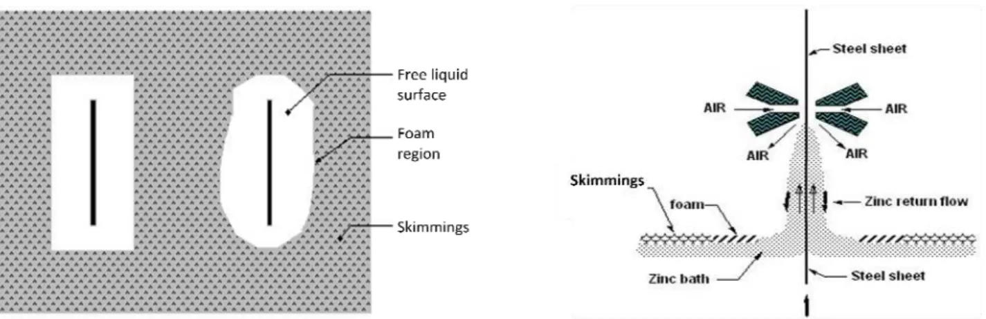
objective of this project consists of a fundamental study of the interaction of the gas jet from the wiping knives on the return flow of the zinc to the bath along the emerging strip. This interaction results in the oxidation of the descending zinc flow which contributes to the skimmings that collect at the bath surface. Generation of top (Fe2Al5Znx) and bottom (FeZn10Aly) dross particles within the
bath volume are the result of the reaction of alloy additives [1] to the melt and are controlled by the solubility limits of Fe and Al in the bath. The air/nitrogen jet from the wiping knives impinging on the return zinc flow can produce a foam which is composed of bath liquid solution, oxides and intermetallic particles that collect at the surface. The foam, also known as skimmings, is a
heterogeneous mixture with a frothy surface layer consisting of dispersed particulate material and porosities. A schematic diagram of dross formation and accumulation is shown in Figure 1.
Fig. 1: Mechanism and location of dross formation at the surface of the zinc bath.
To reduce oxidation of the return liquid zinc flow from the wiping system, several operations use a nitrogen gas wiping system instead of air. ArcelorMittal, a sponsor of project ZCO-55, accepted to participate in this study in order to determine the effectiveness of nitrogen wiping by measuring the quantity of produced. They provided the authors with data taken between January 13th and 15th 2009 from their Cleveland hot-dip galvanizing line. The data provided by ArcelorMittal was recorded continuously through the two day period, the process switched from nitrogen wiping to air wiping in the afternoon of January 14th. Moreover, bench scale experiments simulating the formation of skimmings in industry were conducted as well. The apparatus consists of a graphite crucible containing liquid zinc at 460°C which is stirred using a six steel bladed impeller. A jet of either air or nitrogen was directed onto the liquid surface of the bath in order to simulate the agitated surface reaction generated by the wiping system in industry. The experiments serve to see if skimmings produced in the laboratory are similar in composition and morphology to that produced in industry [3]. Furthermore, skimmings production was analyzed over a range of controlled mixing conditions and alloy compositions using both air and nitrogen gases.
METHODOLOGY
On-line Sampling of Top Dross
ArcelorMittal has dedicated pots for GA and GI operation which can be put on line in a period of about 2 hours for the transition from one product to another. The GI pot is 3.7m by 4.7m with depth of 2.84m and has a 300 tonne melt capacity. A 25 tonne premelt pot is used for both GA and GI operations, only the ratio of SHG 99.99wt% and CGG 0.5wt% Al zinc ingots is varied to maintain the desired effective aluminum content of the bath. The effective aluminum content of the bath is continuously monitored by an electrochemical probe which is immersed in the bath as shown in Figure 2. Operating line parameters were collected from the data logging system identifying all coils and the coating conditions that were used in the process. The parameters monitored consisted of line speed, strip width and thickness, steel grade, top and bottom side wiping knife pressure, wiping knife height above the bath, top and bottom side wiping knife to strip distance, top and bottom side coating weight, Al content of the bath and temperature. Finally, a rate of skimmings generated was calculated based on the weight removed by a robot throughout the process. A scale is positioned under a steel bucket where the robot places the skimmings. A portable oxygen analyzer was used to measure the oxygen content approximately 5cm above the bath surface. While using nitrogen as the wiping gas, GA operation maintained an oxygen level of about 17mol% above the bath. During GI operation, the oxygen level was roughly 20mol%.
Fig. 2: Schematic of ArcelorMittal Cleveland HDGL
Bench Scale Experimental Apparatus
As seen in Figure 3, the experimental apparatus consists of a graphite crucible containing liquid zinc at 460°C which is stirred using a six bladed steel impeller. The crucible has a diameter of 16.5cm and a height of 23cm. The maximum load of the crucible never exceeded 20kg in order the avoid spilling at high mixing rates. Furthermore, the steel impeller served as a continuous source of iron to the system simulating the contact with steel coils in the continuous galvanizing process. An alumina lance, 5mm in diameter, delivered a jet of either nitrogen or air onto the liquid free surface at a flow rate of 10 SLPM. The lance was held approximately 5cm from the free liquid surface. The gas jet was used to simulate the effects of the gas wiping system in the industrial process. The rate of skimmings generated for variable rotational speeds was measured for zinc compositions
corresponding to GA and GI operations. Moreover, the temperature of the bath and the oxygen content above the free liquid surface were monitored using a thermocouple and an oxygen probe. A second set of experiments was conducted under the same conditions using a shroud which
prevented oxygen infiltration to the liquid free surface when a nitrogen jet was used.
Fig. 3: Open (left) and shrouded (right) experimental skimmings generation apparatus
Numerical Simulation of Zinc Flow in the Crucible
A numerical simulation of the flow and mixing of the zinc in the crucible was carried out to determine the surface area and shape of the liquid zinc exposed to the gas stream [2]. As seen in Figure 4, surface area increased sharply above 100rpm due to vortex formation and turbulence of
the liquid zinc surface. This calculation was used to determine the rate of skimmings generated per unit surface area for each rotational speed.
Fig. 4: Free liquid surface area (left) and velocity (right) in the crucible as functions of rotation rate
Metallographic Analysis of Dross
Representative portions of the collected samples were mounted in bakelite moulds and polished for metallographic analysis. Features such as intermetallic inclusions, oxide particles and porosities were identified and analysed from images produced using electron microscopy. Secondary electron and electron backscatter images were generated for the representative samples. In addition, energy dispersive X-ray analysis of the different particles and matrix were also carried out. Elemental mapping of the samples was also used to illustrate the distinct Zn distribution in selected areas, identifying Fe2Al5Znx and FeZn10Aly particles as well as oxides of Zn, Al and Fe.
RESULTS
Analysis of Skimmings Generation: ArcelorMittal Cleveland’s HDGL
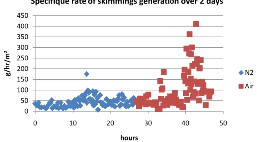
The data represents two complete days of continuous GI operation at ArcelorMittal Cleveland’s HDGL. Approximately midway through this period, the line switched from N2 wiping to air wiping
as seen in Figure 5. Among others, the operating parameters provided by the plant included the mass of skimmings collected per coil, the coil surface area and its residence time in the GI bath. Therefore, a specific rate of skimmings generation per coil at the plant was calculated and its units are g/hr/m2. The shift from N2 to air wiping occurred approximately 27 hours after the start of the
monitoring test. The specific rate of skimmings generation remains stable 6 hours into N2 wiping
but begins to destabilize after the 33 hour mark. Clearly, as seen in Figure 5, air wiping has a significant effect on the amount of skimmings produced compared to N2 wiping.
Fig. 5: Specific rate of skimmings generation per coil vs. time at ArcelorMittal Cleveland’s HDGL 0 50 100 150 200 250 300 350 400 450 0 10 20 30 40 50 g/hr/m 2 hours Specifique rate of skimmings generation over 2 days N2 Air
The instantaneous specific rates of skimmings generation shown above were summed over time in order to produce the cumulative specific rate of skimmings generation curve shown in Figure 6 below. The linear segments are the periods of time when line speed and wiping knife pressure are nearly constant. “Bumps” in the curve occur when there is a change in these two parameters. Between 0 and 10 hours, the line operates at a line speed of 2.1m/s and a wiping pressure of 0.31barg. The line speed and wiping pressure changed to 2.3m/s and 0.45barg between 20 and 30 hours and to 1.9m/s and 0.12barg between 40 and 43 hours. It was previously shown [3] that the rate of skimmings formation is sensitive to both line speed and wiping knife pressure. In the present analysis, it can be shown that skimmings formation becomes significantly more sensitive to these two parameters when an air whipping is used over N2 wiping.
Fig. 6: Cumulative specific rate of skimmings generation per coil vs. time at ArcelorMittal Cleveland’s HDGL 0 2000 4000 6000 8000 10000 12000 14000 0 10 20 30 40 50 g/hr/m 2 hours Cumulative specifique rate of skimmings generation over 2 days N2 Air 0.45 barg 2.3 m/s 0.12 barg 1.9 m/s 0.31 barg 2.1 m/s
Analysis of Skimmings Generation: Bench scale apparatus
A series of bench scale experiments were conducted for GA compositions ranging between 0.11 and 0.14wt%Al. Two cases were examined: a shrouded crucible using both air and N2 impinging
Table 1: Rates of skimmings generation under air/N2 and open/shrouded conditions
Shrouded crucible Open crucible
GA-N2 GA-Air GA-N2 GA-Air
T bath (°C) 461 458 458 467
[O2] above bath (mol%) 0.00 20.91 9.76 20.90
Generation rate (g/s) 100 rpm - - 0.0248 0.0359 200 rpm 0.0653 0.0914 0.0539 0.125 250 rpm 0.0812 0.141 - - 300 rpm 0.0771 0.303 0.291 0.805 Specific generation rate (g/s/m2) 100 rpm - - 1.15 1.66 200 rpm 2.30 3.21 - - 250 rpm 2.56 4.46 1,89 4.41 300 rpm 2.21 8.69 8.34 23.1
The average skimmings generation rate is the ratio of mass of skimmings produced over the duration of the experimental run. The average specific skimmings generation rate is the ratio of average skimmings generation rate to the free liquid surface area [2] for a particular rotation rate. Clearly, the use of an air jet significantly contributed to the formation of skimmings especially at high impeller rotation rates. Moreover, it is evident that shrouding the bath over a N2 jet inhibited
the formation of skimmings to a greater degree than all the other cases. Figure 7 below is a plot of average specific skimmings generation rate as a function of impeller rotation rate for GA and GI compositions ranging between 0.11-0.14wt%Al and 0.16-0.19 wt%Al respectively. The data collected would suggest that at low rotation rates, the specific rates of both GA and GI bath
compositions produce similar amounts of skimmings but that is no longer evident at higher rotation rates. Furthermore, the specific rate of skimmings generation for GA remains relatively constant over the range of rotation rates used.
Fig. 7: Specific rate of skimmings generation vs. impeller rotation rate for both GA and GI 0 1 2 3 4 5 6 150 200 250 300 350 Specific skimmings rate (g/s/m 2) RPM Shrouded‐N2: GA vs. GI GI GA
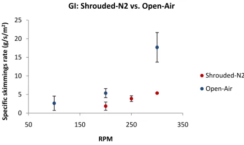
Figure 8 below compares the limiting cases of a shrouded crucible using nitrogen and an open crucible using air for a GI composition ranging between 0.16wt%Al and 0.19wt%Al. The data depicts the contribution of air to the amount of skimmings formed at high rotation rates.
Fig. 8: Effect of air on the specific rate of skimmings formation for GI 0 5 10 15 20 25 50 150 250 350 Specific skimmings rate (g/s/m 2) RPM GI: Shrouded‐N2 vs. Open‐Air Shrouded‐N2 Open‐Air Skimmings Characterization
Previous analyses [3] have shown that industrial skimmings have a large variability in composition and microstructure. The same can be said in the present study upon examining polished sections of the skimmings samples collected in the laboratory. Images of the samples taken by dispersive X-ray mapping are presented in Figures 9a, b, c and d. The images display the Zn distribution across the sample surface area. The composition is heterogeneous consisting of a mixture of intermetallic particles of either, or both, Fe2Al5Znx or FeZn10Aly. Moreover, the skimmings samples also contain
Zn, Al and Fe oxide films and porosities. Taking Figures 9a and 9b, porosities as well as oxide films are present in the analyzed skimmings sample. As for Figure 9c, porosities mixed in with agglomerations of intermetallic particles and oxides are present in the sample. Figure 9d shows how the oxide films can form envelopes which can encase intermetallic particles and bath solution within them.
Fig. 9c: GA-naked-air-300rpm Fig. 9d: GA-shrouded-N2-300rpm
CONCLUSIONS
1. The analysis of the industrial data showed that line speed and wiping gas pressure were the main variables influencing skimmings formation during nitrogen wiping. Moreover, air wiping significantly contributes to the formation of skimmings even at low line speeds and wiping knife pressure.
2. The analysis of the experimental data showed that the skimmings produced at the bench scale were similar in composition and morphology to those of the ArcelorMittal industrial galvanizing line. The samples were heterogeneous mixtures of bath solution, intermetallic particles of top and bottom dross and zinc, aluminum and iron oxide films.
3. Furthermore, the experiments also showed that skimmings formation increased with mixing rate. GI alloys also produced more skimmings then GA alloys for all mixing rates. Finally, a shrouded crucible using a nitrogen jet exhibited the least amount of skimmings formed. ACKNOWLEDGMENTS
The authors want to acknowledge all the operating staff of ArcelorMittal who participated in coordinating and carrying out the sampling tests. The financial support of ILZRO is also greatly appreciated.
REFERENCES
[1] F. Ajersch, F. Ilinca, J-F. Hetu and F.E. Goodwin, “Numerical Simulation of the Rate of Dross Formation in Continuous Galvanizing Baths”, Iron & Steel Technology, August 2006
[2] F. Ajersch, F. Ilinca, F.E. Goodwin, “Numerical Simulation of Dross Formation and Minimization in Continuous Galvanizing Baths”, GALVATECH 11, Genoa, Italy, June 2011
[3] F. Ajersch, C. Koutsaris, S. G. Fountoulakis, M. A. Miller, F. D. Barrado and F.E. Goodwin, “Characterizing Top Dross Sampled from Galvanizing Lines using Nitrogen and Air Wiping Systems”, Proceedings of Galvanizers Association Meeting, Louisville, KY, October 2009