THE DESIGN OF A COMPLEX SOFTWARE SYSTEM
USING A SOFTWARE ARCHITECTURE APPROACH
Djamal BENNOUAR
Saad Dahlab University 09000 Blida, Algeria [email protected]
Abberrezak Henni
INI, Oued Smar 16000, Algiers, Algeria [email protected] Abdelfettah saadi CDTA,Baba Hassen, 16000, Algiers, Algeria [email protected]
Abstract: Software development using software architecture approaches and aspect oriented programming represents today a very promising way for the design of high quality software at lower costs. The Integrated Approach to Software Architecture (IASA) is an Aspect Oriented Software Architecture Approach using a component model totally independent from any software mechanism, mainly the interface concept. The IASA component model provides facilities not supported by nowadays software architecture tools to easily specify any topology an architect can imagine. It is used here to show how it is easy to design at a high level of abstraction, an EGovernment application using an Aspect Oriented approach.
Keywords: Software Architecture, Component, Port, Connector, Aspect, E-government.
1 INTRODUCTION
A number of research works were conducted during the last decade concerning software architecture specification. These efforts resulted in the proposal of a great number of ADL. The work presented in [1] summarizes the characteristics of these ADL and discusses the main concepts of Software Architecture such as components, ports, composite component or configuration and connectors. Until now, proposed ADL have not known the awaited success. This is due to several factors, such as
- The orientations to solve problems in a specific domain[2]
- The orientation to deal with a particular architectural style [3]
- The exclusive use of formal languages like CSP[4] which are not suited for practitioners. - The difficulty to design GUI based application. - The component interaction model is usually
based on the interface concept which heavily constrains the specification of architecture to a restricted set of well known topologies fully influenced by the software mechanism, mainly the procedure call mechanism.
The IASA approach [5],[6] was introduced to fill most of these deficiencies. It offers an attractive alternative for the practitioners allowing them to specify architecture with a high degree of freedom from any software mechanism constrain. In addition, IASA support natively Aspect Oriented Software Architecture (AOSA)
specification which reinforces one step further the modularity of a software system.
In this paper we deal with the design of an EGovernment application using the IASA AOSA. Java web technology represents in this experience the targeted implementation technology.
In the remaining of this paper, we will briefly present, in section 2, the fundamental concepts of Aspect Oriented Programming (AOP) and AOSA. Section 3 deals with IASA fundamental model element and with joinpoint specification technique. A joinpoint is one of the basic elements of AOP. In section 4 we introduce the global objectives of the EGovernment project we realized using the IASA elaboration process. This later is presented in section 5 and section 6 partially shows its application in order to produce the EGovernment software product. Section 7 briefly presents the transformation technique used to generate the application in the targeted implementation technology and section 8 concludes this work by outlining some challenges facing the IASA approach in the design of Multi tiered application based on HTTP servers.
2 ASPECT ORIENTED PROGRAMMING
Aspect-Oriented Programming (AOP) is a recent software programming paradigm that aims at providing a better separation of concerns and reinforces one step further the modularity of a software system specification. Aspect Oriented Software Architecture (AOSA) is a recent trend in Software Architecture [7],[8,]. The most interesting works in Component Based Software Architecture deals with aspect either at a level of abstraction directly related to implementation level [9],[10],[11], or use an existing component model [12],[13] which is usually extended by the definition of specific interfaces, connectors and components.
AOP and AOSA are based on the following five concepts[14]: joinpoint, pointcut, advice, weaver and advice insertion mode. An advice represents the logic of a specific concern. The joinpoint indicates the location in the core business concern where the code must be altered by injecting the advice to produce the final system. The injection is achieved through a special mechanism called the weaver. The pointcut, specified usually as a regular expression, is a set of joinpoint where the advice has to be weaved. The advice insertion mode specifies how to operate the advice at a pointcut level. The most cited advice insertion modes are: before (the advice is
performed before the joinpoint), after (the advice is performed after the joinpoint), and around.
The advice code corresponding to the around insertion mode, contains a first part that must be executed before the joinpoint and second part that must be executed after the joinpoint. The execution of a service with an around insertion mode is usually achieved as follows:
- The advice before part is executed.
- An optional call to a special instruction usually named proceed is made. This later launch the execution of the service attached to the joinpoint (a piece of code in programming language such as AspectJ[14].
- The advice after part is executed.
- The program execution is resumed just after the joinpoint.
The call to proceed may depend on the result of the advice before part logic. If proceed is not called, the joinpoint service is not executed, and the program execution resumes just after the joinpoint.
3 THE IASA BASIC MODEL ELEMENTS
IASA is based on the following concepts: access point, port, component, envelope, connector and action [6]. These elements represent the fundamental concepts of the IASA ADL called SEAL (Simple and Extensible Action, Architecture and Aspect Language)[18]. The action concept, largely inspired from the OMG Precise Action Semantic[15]), is used to describe miscellaneous architecture behaviors.
3.1 The IASA component Model
The IASA component model defines a specific organization for the internal view |8] which consists of two parts: the operative part and the control part. The operative part handles the core business aspect. The control part is composed of a controller and number of aspect components (i.e. tracing, exception, transaction) providing the technical advices [16]. An aspect components is instantiated in the whole application as a singleton.
3.2 The Envelope Concept
The main goal of the envelope is to provide a total isolation of the internal view of a component from the external world. The envelope is mandatory in the process of instantiating a component type. The envelope represents a sort of clothes an instance of a component type wears in a specific situation. The envelope specifies for a component instance its deployment case which describes the deployment environment (machine, operating system, process, application server) and the exact nature of the component in such environment (PROCESS, MAIN THREAD, THREADS, SERVLET, EJB etc.).
An envelope hosts all the resources needed to support communication aspect (i.e. adapters), to enable the specification of connections involving the port's
structural elements and to handle aspects weaving operations of code.
3.2.1 IASA Link Component
The link component (LinkCmp) is used to represent the same component instance across the composition hierarchy of an application, in order to produce lucid and clear architecture specification and to avoid proliferation of delegation connector. The LinkCmp provides more than the concept of shared component of FRACTAL[17]. The LinkCmp provides means to attach to a same component instance, different personalized external view, in the same or in different level of the composition hierarchy. The personalization of LinkCmp is mainly achieved by using the alias construct of the SEAL language either to personalize the action name describing the port behavior [18] or to associate an action to a specific aspect insertion mode (before, after, around)[16].
3.3 The Access Point Concept
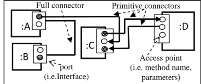
An access point is the smallest structural element in the specification of an application [6]. It is used to define the ports of components. An access point exposes required or provided resources which may be data or operations. Communication mode and the resource time validity are among the properties of an access point. An access point may be wired in an independent manner to another access point which is hosted in the same or a different port (Figure 1).This is not the case in current software architecture models and tools, where an interaction point, usually represented by an interface is considered as an atomic element despite its complexity.
The access points are organized into two categories (Figure 2): The Data Oriented Access Point (DOAP) and the Action Oriented Access Point (ACTOAP). An ACTOAP plays one of two basic roles: a server role or a client role. It supports a set of actions indicating the provided or required operation. A DOAP is usually provided with two specific actions: the send and receive actions.
Fig. 1: IASA Connectors based on port's element Access point (i.e. method name,
parameters) port (i.e.Interface)
:A
:B
:D
:C
Full connector Primitive connectors
Fig. 2: Graphic notation of Access Point and ports
DOAP and ACTOAP (Notation used to show port’s detail) DOAP out DOAP in ServerPoint ClientPoint PORTS: Notations appearing on the boundary of a component
3.4 Ports
A port is a regrouping technique of related access points. It maintains an abstract and a concrete views. The abstract view is represented by the concept of access point, the actions associated with the access point and a behavior. The port's behavior is represented by a set of valid rules defined in the SEAL language. Each rule shows how the required or provided resource must be used. Figure 3 shows a SEAL partial description of port types used in the external view of the CivilStateCmp component type shown in Figure 10.
IASA defines a number of specific ports. Among them (Figure 2) we find the ClientPort, the ServerPort and the AdvicePort. An AdvicePort is a ServerPort provided with actions explicitly associated with supported aspect activation mode. For now, the supported advice activation modes are: aroundFirstAction, AroundLastAction, proceeedAction, beforeAction and afterAction.
3.5 IASA Connectors
The IASA connector model is largely inspired from computer network architecture. The model provides a behavioral view and a structural view. The behavioral view describes an interaction and the structural view defines the infrastructure needed to transport the
interaction. The connector infrastructure is based on two kind of fundamental connector elements:
- Transport Connectors which are point to point connectors composed by Basic Transport Connector, which can connect only two compatible access points (Figure 1).
- Service connectors which are primitive component oriented to support specific interconnection functionality (distribution, multiplexing, load charge balancing, etc.) as described in [19] and [20]. The designer is not concerned by the definition of new Service Connectors or Transport connectors which are predefined in the IASA approach and have a complete realization in the supported implementation technologies. The definition of the interconnection infrastructure is achieved in IASA by cascading Service Connectors using Transport Connectors.
3.6 Pointcut specification
In IASA, a joinpoint is localized only at port level [16]. It may be any action attached to an access point. A joinpoint is identified by a hierarchical name specifying its location in a design. The star character symbols, and SEAL keywords (i.e. (serverport, clientport, dataport, interest, rule, send, receive) may be used to specify joinpoints generic name in the process of a pointcut definition. Operation on set (i.e. union, difference) may also be used to define new pointcuts from others.
4 THE TAGETED APPLICATION
In this experimental study, we realized for the CDTA (Center for the Development of Advanced Technologies at Baba Hassen,Algiers) a software system which enables the citizen to access through the internet to various services of a local government institution called the APC (the town council). The most required services from the APC are the production of official documents exposing important events such as the birth certificate and the marriage certificate. Inside the APC, the service delivering such official documents is called the Civil State Service
The EGovernment system for the APC must provide efficient solutions to the following challenges:
- A huge amount of data describing citizen events has to be captured.
- A high degree of security must be guaranteed to access critical part of the system and personal data The first challenge was solved by defining a strategy where the citizen is indirectly involved in the process of entering data. The main benefit of this strategy is the fact that a citizen natively makes best efforts to guarantee the correctness of data describing him or any of his relatives. In addition, with this strategy, the citizen participates efficiently to highly reduce the problem of errors produced when delivering documents. This first challenge was solved as a part of the core business aspect of the system.
The second challenge was solved by the use of a predefined aspect component belonging to the security aspect of IASA.
// SEAL ADL: file :CivilStatePortType.seal package eapc.ports;
import eapc.doap.*;
// Action context definition
actioncontext citizen_basic_actions {
// all actions of this context are abstract
actions birth , death, marriage,
divorce, family;
} }
port { // Port type definition port DocumentPort { accesspoint{
ServerPoint docSp (0, SYNC);
CitizenIdDataPoint citizenId (OUT, 0, SYNC)
}
actioncontext {
uses citizen_basic_actions;
}
behavior {
rules birth_r, death_r, marriage_r, divorce_r, family_r; rule birth_r { precondition:; pattern: birth;success; postcondition:; fail:; }
rule death_r { // empty section may be omitted pattern: death;success;
}
rule marriage_r {..} rule family_r {..} rule divorce_r {..} }// end of port type behavior } // end of DocumentPort type definition
// other port type definition
}// end of global port type definition
5 THE IASA ELABORATION PROCESS
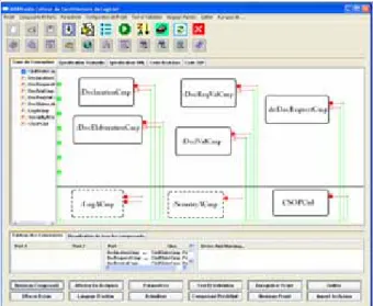
The IASA elaboration phase in the design process of a software system is completely automated in the context of IASA STUDIO (Figure 4). The elaboration process follows a recursive top down strategy made of a two great phases: An initialization phase and a recursive phase.
The initialization phase is concerned by definition of the external view of the whole application and the determination of external component. The recursive phase deals with the design of component’s internal view and its first step target the whole application internal view. In the next section we present a partial view of this process. A complete description may be found in [5]
5.1 Phase 1: Project Initialization phase
5.1.1 Step 1
This step starts with the specification of the application name (AN) and the deployment architecture (DA). Regarding IASA, the application itself is considered as a component type.
5.1.2 Step 2: External view definition
The goal of this step is to define the provided and required services, the definition of actions, the organization of service inside ports and the specification of port’s behavior. The following tasks are performed in an iterative way.
Global informal description: This phase begin with an
abstract definition of the system or component, in the form of only one box from where leave and arrive several arrows. Arrows represent the provided and needed services, data or controls. To eliminate any ambiguities, the boxes and arrow specification must be accompanied by a narration explaining the total functionalities of the system and the semantic associated with the arrows. The narration may also contain the requirements and constraints fixed by the customer.
Resource organization: This task represents the first
task towards formalizing the external view. From the preceding definition, we must define the provided and required resources (services and data). The definition of
services is accomplished by specifying action names and optionally action input and output pins.
Definition of the external ports: The required and
provided resources are gathered in ports according to the supported port type (regular port, controlled port etc.). The behavior of a port is then defined based on the actions defined previously.
At the end of this phase, a full SEAL description of the external view is produced by IASA STUDIO and ready to be transformed in the chosen implementation technology.
5.1.3 Step3:
Let LCmp a set of component and deployment architecture initialized as follows: LCmp = {(AN, DA)}
5.2 Phase 2
This is the recursive phase of the elaboration process. For each pair (ANX, DAX) from LCmp , the following steps have to be performed.
Step 1: Internal view elaboration
This step is concerned by the elaboration of ANX internal view and the definition of the controller behavior. This step is realized as follow:
Let ILCmp an intermediate set of components and deployment architecture pair initialized to empty. While the internal view of ANX is not stable (the stability analysis is done using the SEAL interpreter) perform the following design action
- Find the component type needed to realize ANX. - Define the external view for new component type - Establish / modify / Remove connectors
- Define interaction using SEAL actions
- Define a mapping between external view and internal view (delegation connectors)
- Define / Adjust the behavior of the controller. - Verify the component’s stability using the SEAL
interpreter
- Adjust the external view of new component type - Specify the deployment case for the used instance
according to initial deployment architecture DAX - Add new introduced component type to ILCmp set.
Step 2: End of internal view elaboration of ANX the
ANX component is stable
Step 3: Prepare the next recursion
Add new component types to LCmp: LCmp = LCmp + ILCmp.
Step 4: End of the design elaboration process.
6 THE DESIGN OF THE APPLICATION
In the following we partially show the use of the just introduced elaboration process in the design of the previously described application.
6.1 Phase 1: Project Initialization phase
6.1.1 Identification and deployment architecture
The targeted application is named E_APC. The deployment architecture is represented by the Apache Tomcat HTTP server.
6.1.2 The external view
Global description of the system: Figure 5 presents a
global view of the system which serves as a base for the first formal specification using IASA notation (Figure 6).
Resources organization in the external view: The
preceding informal view is transformed into a more precise view (Figure 6) which would be the starting point for a successive operation of refinement until reaching the desired software product. Figure 6 shows all the ports of the system using the IASA notation and figure 7 present a partial view of the E_APC in the SEAL language.
The interesting observation on the formal specification of the E-APC, according to IASA approach notation (Figure 6), is the lack of ports dealing with access control. This situation is in fact due to the support of aspect oriented software architecture in the IASA approach. In fact, technical aspects have not to be considered when designing the core business aspect. This later has to be designed for an ideal environment which provides necessary technical support to safely operate the core business aspect and decides where and when to place the support.
6.2 Phase 2: internal view LCmp elements
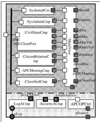
Figure 8 shows some fundamental components of the E_APC internal view. The operative part is composed of six business components and the main view of the E_APC IHM. The control part contains two aspect components in addition to the controller.
6.2.1 Managing the security aspect
The operative part is designed without taking any care concerning security and logging aspects. If at this stage any service has to be secured, the only thing designer has to do is to connect the advice port of the security component to the port providing the service to secure. This operation, called aspect injection, is achieved by specifying the pointcut containing the actions concerned by the security advice. Figure 9 shows how the security aspect is injected in all ServerPort of all business component except those component which do not need to be secured.
. pStarter pLog :SysAdminCmp :CitizenRelationC mp :APCMeetingCmp :CivilStateCmp :ClassifiedCmp :SysInstallCm APCOPCtrl :SecurityACmp :LogACmp pSql :SQLClientPort
Figure 8: partial Internal View of E_APC
pAuthAdvice pLogAdvice : Main View pInstall pDoc pAdmin pDdec pAPCMeeting pOpinion pClassified pDocVal pDdecVal plocalDoc
Figure 6: E_APC external view using IASA notation
pStarter: MainCmpPort pInstall : InstallPort pSql :SQLClientPort
:E_APC
pDoc :DocumentPort pLog : IALogDataPort pAdmin : AdminPort B S P pDec :DeclarationPort B S P pAPCMeeting :APCMeetingP pOpinion :OpinionPollPort B S P pClassified :ClassifiedPort B S P pDocVal :DocumentValPort pDecVal :DeclarationValPort S pLocalDoc :LocalDocPort B S P// SEAL ADL: file : E_APC.seal package eapc.component; import IASA.aspect.*; import eapc.ports; component E_APC{ ports { // The external view
// required Services SQLClientPort pSql; // Provided services MainCmpPort pStarter; InstallPort pInstall ; AdminPort pAdmin ; // … other regular ports here
ClassifiedPort pClassified; // Interest for an Aspect (IA) DOAP
IALogDataPort pLog; } operativepart { components { ……….. } connectors { ………... } } controlpart {…… } }
} //End Description of E_APC component
Fig. 7: Partial SEAL description of E_APC
:E_APC
Requirements Provisions
Fig 5: Informal specification of E_APC
Database connection
Local document
classifier ReqDoc
OnLine APC meeting Declaration DeclarationValidation Access Authentication System Administration Installation Opinion poll
Offline APC deliberation Anonymous Access
The completion of this step results in the complete definition of the external view of new instantiated components type which are added to the LCmp set.
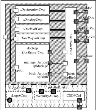
This step is repeated for each new introduced component type. In the following we will focus our interest in the design of the CivilStateCmp, which is the most important component in the E_APC application.
6.2.2 The internal view of CivilStateCmp component It is composed of a number of components, each one oriented to handle a specific functionality of the civil state department of the APC (figure 10).
The components DeclarationCmp and DocReqCmp are oriented to enable the participation of the citizen in the process of populating the E_APC databases with accurate data concerning them. DeclarationCmp handles the declaration of new events such as birth, death, marriage or divorce. DocReqCmp is used to request miscellaneous certificates and, in the same time, is used to enter citizen data if these later were not yet captured in a previous declaration or document request.
The validation components (DeclValCmp and DocReqValCmp) are used to validate data entered by citizen either with DeclarationCmp or DocReqCmp. The DocReportCmp is used to produce the desired certificate. We notice in this internal view the use of link component to represent the security and log aspect component previously instantiated in the E_APC internal view.
We also notice that there is no need to secure the access for DeclarationCmp and DocReqCmp since these components are oriented to encourage citizen to enter
their data and participate in the whole process of capturing citizen miscellaneous information. However, in the previous step we have injected the security aspect at all server port, which means that all actions at those ports are targeted by the security advice. Consequently, the server ports (spBirth, spMariage etc..) of DeclarationCmp and DocReqCmp find themselves secured. To solve this sort of problem we have two solutions:
- Review the injection statement in the internal view of E_APC.
Adjust the security aspect injection of a previous step using the aspect remove capability of the SEAL language (Figure 11).
7 GENERATING THE APPLICATION
The final form of the generated application code depends on the application’s deployment map (Figure 12) which specifies the deployment case for each component instance of the tree representing the composition hierarchy of an application.
Fig. 10 : CivilStateCmp partial internal view
spReqDoc spDdec :DocReqCmp :DeclarationCmp :DocReqValCmp :DeclValCmp spReqDocVal spDdecVal CSOPCtrl :SecurityACmp :LogACmp pAuthAdvice docRep :DocReportCmp spGetDoc pLogAdvice :CivilStateView birth :Action mariage :Action cpBirth spBirth cpSql spMariage birth :Action
// SEAL ADL: file :CivilStateCmp.seal
package eapc.component;
import IASA.aspect.*, eapc.ports.*; component CivilStateCmp { ...
aspect { // Aspect pointcut and advices management
pointcuts {
not_secured = { DeclarationCmp, DocRequestCmp }; // other pointcut definition …….
}
advices {// Advices management // Adjust security injection
remove secCmp. pAuthAdvice from not_secured;
// other advices management …
}
……
Fig.11: Adjusting security aspect injection
// SEAL ADL: file : E_APC.seal package eapc.components; import IASA.aspect.*; import IASA.ports.*; component E_APC{ ports { ...} operativepart { components { ……….. } connectors { ………... } } controlpart { components { APCOPCtrl apcOPController; SecurityACmp secCmp; LogACmp logCmp; }
aspect { // Aspect pointcut and advices management
pointcuts {
all_services={ serverport}
not_secured = { CitizenRelationCmp, APCMeetingCmp, ClassifiedCmp};
partial_secure = all_services – not_secured // other pointcut definition …….
}
advices {// Advices Management
inject secCmp. p.AuthAdvice around partial_secure;
// other advices management operation …
}
interest {// Interest for Aspect Management }
}
} //End Description of E_APC component
A set of transformation rules takes a SEAL description and produce the code in the desired implementation technology. In the following we briefly present the main transformation rules used in the process of generating the E_APC application.
- An aspect component is always deployed as an ordinary java class (or a java bean) provided with a number of static methods. Each static method is designed to handle a specific action belonging to the supported aspect activation mode.
- Since the application belongs to the EGovernment domain, any browser communication bypassing the HTTP protocol is not supported (i.e. Java RMI). Hence, it is not possible to deploy a component as an APPLET if this component is provided with port using a non HTTP communication protocol.
- For component deployed as JSP, Applet or JavaScript, there is no need for connector adapter since all used connectors and ports are based on standard protocol (HTTP, SQL).
- Due to the stateless nature of the HTTP protocol, the the aroundLastAction of the around activation mode is only executed if the advised joinpoint is not executed.
- The weaving of aspects is always located in the client port connected to the targeted server port containing the joinpoint. It is achieved at the envelope level and results in the modification of the port behavior.
The examples in figures 3,9,10,11, and the following figures briefly outlines some elements of the transformation process. Figure 3 shows the original port’s behavior designed far from technical aspect. This port’s behavior is attached to the server port (spBirth) of DocReportCmp and the corresponding client port (cpBirth) of CivilStateView (Figure 10). Usually we encounter compatible behavior in the connected client and server ports.
Figure 13 shows the behavior of the client port after the injection of the security aspect as specified in figure 9 and 11.
Figure 14 illustrate the technique used in IASA approach for a component to contact the external world. The service call represented by a link in the CivilStateView deployed as a JSP page, is first directed to the component’s port (cpBirth) and not directly to another component.
To insure the total isolation of a component type from any instantiating environment, the service call is redirected to the envelope used to instantiate the component type (Figure 15). All modifications needed by aspect weaving are located in the envelope. Figure 16 shows the connector implementation code represented by a redirection of the service call from the envelope to the envelope of connected server port (spBirth).
<a href=”ports/cpBirth.jsp”> birth certificate </a>
Fig.14: inside the CivilStateView code
rule birth_r { precondition:;
pattern: ArounfFirstAction; proceedAction |birth; aroundLastAction;success;
postcondition:; fail:; }
Fig. 13: weaving aspect at port behavior level
<!-- Redirect to the envelope port -->
<jsp:forward page=""../envelope/active/cpBirth ">
Fig. 15: Inside cpBirth.jsp
Fig. 16: Inside the envelope port cpBirth.jsp
<%@ page contentType="text/html; charset=utf-8" language="java" %>
<!-- Redirect to the connected port. use of absolute parth --> <jsp:forward
page="/CivilStateCmp/docRep/envelope/active/spBirth.jsp" >
<%@ page contentType="text/html; charset=utf-8" language="java" import="iasa.security.*" %>
<!— Boolean Aspect DOAP : Transformation process --> <%=boolean proceedState = true%>
<!-- --- --- Around body part 1 -->
<% AuthACmp.pAuthAdvice.aroundFirstAction; proceedState =
AuthACmp.pAuthAdvice.proceedAction; If (proceedState) {
%>
<!-- --- --- Around body end of part 1 -->
<!-- Redirect to the connected port. use of absolute parth --> <jsp:forward
page="/CivilStateCmp/docRep/envelope/active/spBirth.jsp"> <!-- --- --- Around body part 2 -->
<%}
AuthACmp.pAuthAdvice.aroundLastAction; %>
<!-- --- --- Around body end of part 2 -->
Fig.17: The envelope after aspect Injection
////// File E_APC.dpy
// Description of recognized deployment architecture and // deployment case package eapc.component component E_APC { architecture { environment tomcat { machine localhost;
container tomcat5.5 ; //apache Tomcat 5.5 namespace eapc ; //localhost:8080/eapc os UNIX; // Generic name used.
deploymentcase {APPLET, JAVASCRIPT,JSP, SERVLET, BEAN, CLASS}
} // Many environment may be defined.
}
// Definition of the deployment map.
// Many maps may be defined for the same application
deploymentmap map_for_tomcat {
deploy this as JSP in tomcat; // produce E_APC.jsp
// rall : Recursive Deployment: Target composition tree deploy rall as JSP in tomcat ;
}
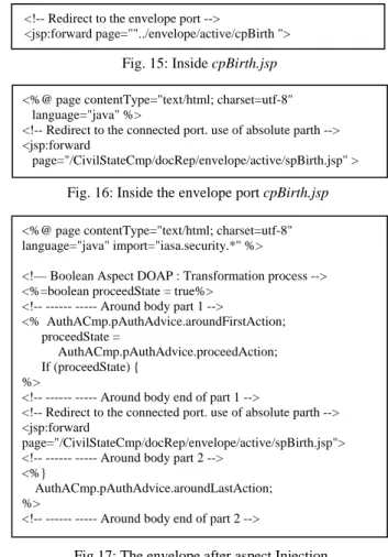
Figure 17 presents the result of weaving the security aspect using the around activation mode. We notice in figure 17 that the after part of the around activation mode is executed only if the proceed part indicates that the join point is not executed.
8 CONCLUSION
The work described in this paper is an actual experience where a software architecture approach is used to realize a complex EGovernment software system deployed in Java web technology. In this experience, the IASA approach and its software elaboration process were conducted in parallel with the realization of the same product using the EJB component model and the elaboration phase of the Catalysis object oriented design process [21]. This experience showed the high flexibility and the power of IASA to easily handle software architecture specification and to reduce the realization time. Compared to the object oriented project realized using an object oriented approach based on EJB, the realization time in IASA using Java web technologies was by far the shortest.
This time performance may be explained by the following facts
- The use of EJB in the context of an object oriented approach requires the direct control of several technologies (Servlet, JSP, JavaBeans, EJB, XML etc.) and concepts, whereas in IASA, the only concepts to be acquired are the fundamental concepts of software architecture (component, port, connectors)
- The concepts of composition, link component and the aspect management facilities provided by SEAL language. These concepts allowed the designers to follow a clear and organized top down design process as shown in this paper. The composition concept is not natively supported by the EJB component model.
This achieved work has also shown some challenges the IASA approach is currently facing. Currently, the main challenge is located in the transformation process from an abstract view described in SEAL to a concrete view, represented in one or more implementation technologies. The transformation process, as in [22], produces a great amount of code. This situation is mainly due to the envelope concept which is associated with each component instance. Optimizing the number of envelope in the transformation process represents one of the planned future works in the IASA approach
9 REFERENCES
[1] N. Medvidovic, R. N. Taylor, “A Classification and Comparison Framework for Software Architecture Description Languages”, IEEE Transactions on Software Engineering, Vol. 26, no1, pp. 70-93, January 2000
[2] Vestal, S., 1993. Scheduling and Communicating in MetaH. Real-Time Systems Symp., pp: 194-200, Raleigh-Durham (NC).
[3] Medvidovic, N., R.N. Taylor and E.J. Whitehead, Formal modeling of software architectures at multiple levels of abstraction. Proc. California Software Symp., pp: 28-40, 1996, Los Angeles, CA.
[4] R. J. Allen, “A Formal Approach to Software Architecture”, PHD Thesis, May 1997, http://www-2.cs.cmu.edu/afs/cs/project/able/www/able
[5] D. Bennouar “The Integrated Approach to Software Architecture”, Internal Report, IR2008/SAP03, LRDSI Lab, CS Department, The Saad Dahlab University, Algeria, Jan. 2008 (in French),
[6] D. Bennouar, T. Khammaci, and A. Henni, A New Approach To Component's Port Modeling In Software Architecture, ACIT’2007, Lattikia, Syria, Dec; 2007
[7] Krechetov, B. Tekinerdogan, A. Garcia, C. Chavez, and U. Kulesza. Towards an Integrated Aspect-Oriented Modeling Approach for Software Architecture Design. in 8th International Workshop on Aspect-Oriented Modeling, AOSD 2006. 2006. Bonn, Germany
[8] A. Navasa, M. A. Perez, J. Murillo, and J. Hernandez. Aspect oriented software architecture: a structural perspective. In Proceedings of the Aspect-Oriented Software Development, 2002, The Netherlands. [9] Aldrich, J. (2005). Open modules : Modular
reasoning about advice. In ECOOP 2005 - Object-Oriented Programming, 19th European Conference, Glasgow, UK, July 25-29, 2005,Proceedings, volume 3586, pages 144–168. Springer. 86
[10] Norman Richards, Marc Fleury, Scott Stark, JBoss 4.0 - The Official Guide, Sams, April 2005
[11] Davy Suvée, Wim Vanderperren, and Viviane Jonckers. JAsCo: an aspectoriented approach tailored for component based software development. In Proceedings of the 2nd international conference on Aspect-oriented software development, pages 21_29. ACM Press, 2003.
[12] H. Fakih, N. Bouraqadi, and L. Duchien. Aspects and software components: A case study of the fractal component model. In International Workshop on AOSD, Beijing, China, September 2004.
[13] N. Pessemier, Unification of aspects and components approaches PhD thesis, Université of Science and Technologies,Lille, France, June 2007 [14] Russ Miles - AspectJ Cookbook – Real World
Aspect Oriented Programming with Java, O'Reilly, 2005
[15] OMG, Action semantics for the UML, Final submission. TR, Object Management Group, 2001 [16] D.Bennouar, “Aspect Oriented Software
Architecture in the IASA Approach”, Internal Report, IR2008/SAP05, LRDSI Lab, CS Department, The Saad Dahlab University, Algeria, May 2008.
[17] Bruneton et al., 2006] Bruneton, É., Coupaye, T., Leclercq, M., Quéma, V., and Stéfani, J.-B. The fractal component model and its support in java. In Software Practice and Experience, special issue on Experiences with Auto-adaptive and Reconfigurable Systems, 2006.
[18] A. Saadi, An action language for the specification and validation of software architecture behavior, Magister Thesis, LRDSI Lab, Computer Science Department, The Saad Dahlab University, Blida, Algeria, June 2008.
[19] N.R. Mehta, N. Medvidovic, S. Phadke, Towards a Taxonomy of Software Connectors, Proceedings of ICSE2000, May 2000.
[20] T. Bures, F. Plasil, Scalable Element-Based Connectors, Proceedings of SERA 2003, SF, USA, June 2003.
[21] D’Souza Desmond et Alan Wills. Objects, Components and Frameworks With UML : The Catalysis Approach.. Addison-Wesley, 1999
[22] Karl J. Lieberherr: Adaptive Object-Oriented Software: The Demeter Method with Propagation Patterns. PWS Publishing Company, International Thomson Publishing, Boston, 1995.